Table of Contents
Advertisement
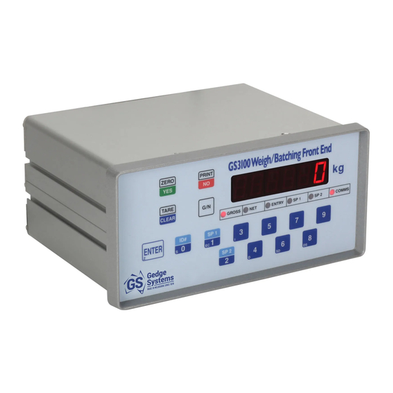
GS3100 Weigh/Batching Front End
Op er ating & In stal la tion Man ual.
NOW AVAILABLE WITH OPTIONAL MODBUS ASCII & RTU SERIAL I/O
and HIGH PRECISION ANALOG OUTPUT OPTION
Year 2000 Compliant
488 Church Street, Richmond, Victoria, 3121, Australia.
Phone +61 3 9429 8396. Fax +61 3 9429 8097.
Email gs3100@gedgesystems.com.au
Issue 6 of November 2005
Copyright GS Systems Pty Ltd
ABN 18737137544
All Rights Reserved
Advertisement
Table of Contents

Summary of Contents for Gedge Systems GS3100
- Page 1 GS3100 Weigh/Batching Front End Op er ating & In stal la tion Man ual. NOW AVAILABLE WITH OPTIONAL MODBUS ASCII & RTU SERIAL I/O and HIGH PRECISION ANALOG OUTPUT OPTION Year 2000 Compliant 488 Church Street, Richmond, Victoria, 3121, Australia.
- Page 2 “3100.7A” or “3100.7b”. The “7” part of the message is the software version number, the “A” identifies the unit as a “standard” GS3100 and the “b” identifies the unit as one fitted at the factory with the OPTIONAL MODBUS serial I/O.
-
Page 3: Table Of Contents
In tro duc tion Ap plying Power, Re tained & Cleared Set tings, Se rial I/O Con sid er ations. Mes sages & their mean ing in clud ing the 3 meth ods of lock ing the GS3100's keys. Front Panel Dis play Front Panel Lamps 10 2.6... - Page 4 26 3.16 Con necting the Stan dard RS- 232C Se rial Out put & the Set Point Con trol Out puts. 27 3.17 Elec tri cal Speci fi ca tion of the GS3100's Set Point Non- Latching Out puts. 28 3.18 Spike and Tran sient Sup pres sion of Switched Load Noise.
-
Page 5: Introduction & Features
Computer. Immediately the Computer puts the GS3100 into “terminal mode”, all operations of the GS3100's front panel keys are sent to the Computer and not acted upon by the GS3100. During all of this time, the GS3100 continues weighing and set point operations without interruption. - Page 6 Not a Panel meter. The GS3100 is a proper full function weight indicator. It is designed and manufactured by Gedge Systems who has international weights and measures approvals for weight indicators and controllers.
-
Page 7: Operating The Gs3100
3100.7b This identifies the product as a GS3100, with factory installed “MODBUS3100" Option fitted. Software version 7 installed. The GS3100 is type b. 888888 The GS3100 “turns on” all the bars of its display and all of its six lamps to verify that they are working properly. -
Page 8: Mes Sages & Their Mean Ing In Clud Ing The 3 Meth Ods Of Lock Ing The Gs3100'S Keys
Damaged load cell circuit to the GS3100. Incorrect connection to the GS3100 of the load cell cables. A failure of the GS3100's load cell input. If the GS3100 displays weight when a star bridge or load cell simulator is properly connected to it, the fault will be in the load cell circuit external to the GS3100. -
Page 9: Front Panel Dis Play
ID numbers are displayed. Finally, the GS3100's display may contain none of these. Instead, it may contain a message that has been sent to it from a remote computer or PLC (from across the room or across the world). If this is the case, the messages and their meaning should be contained in the documentation supplied with your weigh batching systems. -
Page 10: Key Board Con Trols
ENTER again to save it. The GS3100 momentarily blanks its display to signify a successful operation. If you try to enter a set point value that is too large, the GS3100 will warn you with a message “too Hi”. -
Page 11: Full Installation Details
3.1 In stal la tion steps. The list below shows each of the steps required for the installation of the GS3100. They are listed in the order in which they should be carried out. The paragraphs that follow, which are presented in the same order as the list, describe in detail each of the steps. -
Page 12: Un Packing The Gs3100
Do not dispose of the GS3100's shipping container. In the unlikely event of a fault developing at some time in the future, you will need it, to ensure that the GS3100 can be securely and safely shipped back to Gedge Systems for repair. -
Page 13: An A Log Out Put Option6Hpf (High Pre Ci Sion Fast Clock Rate
Now apply power to the GS3100. There is no need to connect a load cell to the GS3100 in order to adjust the Option6HPF's analog output. If a load cell is connected there is no need to remove it as it will not affect the adjustment procedure. -
Page 14: Con Nec Tions And Spec I Fi Ca Tion
A mating male cable connector is supplied with each option. To minimize noise use a shielded cable with the shield grounded only at the GS3100 end by crimping it between the metal backshells of the cable connector & connecting to Pin 1 Frame. -
Page 15: In Stalling An Op Tional Se Rial Card Into The Gs3100 & Set Ting Its Baud Rate
RS-422 or 20mA current loop is needed for long cable runs, then the GS3100 can be fitted with an optional serial output card. Alternatively, if the full power of the GS3100 is to be obtained, the GS3100 can be fitted with a serial input/output card. -
Page 16: Se Lecting Iso Lated Or Non-Isolated Op Era Tion Of Se Rial Op Tion Cards 202, 207, 07 & 08
3.8 Set ting the baud rate for the GS3100's stan dard RS- 232C se rial out put. If the GS3100's standard serial output is to be used, rather than an optional serial card, the baud rate must be selected from the two choices available. -
Page 17: Con Necting Load Cells
3. The user must decide whether to use the GS3100's excitation ratio sense or not. If the sense is not used, the installation will be sensitive to variations in the excitation supply across the load cell. These are caused by changes in the resistance of the load cell cables and by time and temperature changes in the excitation supply. -
Page 18: Con Necting To The Mains Sup Ply
3.10 Con necting to the Mains Sup ply. The GS3100 may be connected to the local power supply directly, or through an isolation switch, but always in compliance with the local electricity authority's codes of practice. In any event, the means must be made available to remove power from the GS3100 during service or any activity involving access to the interior of the GS3100. -
Page 19: Use Of The Gs3100'S Keys For Cal I Bra Tion And Pro Gram Ming
3.11.3 Use of the GS3100's keys for calibration and programming. The GS3100's keys which are used for calibration and programming are shown in the drawing below. They contain a letter or letters at the lower left to identify their use. -
Page 20: Dig I Tal Setup - Pro Gram Ming The Gs3100
The tables on the following pages list each of the digital setup settings together with symbol examples of the settings. The settings are listed in the order in which they are displayed by the GS3100 as the “Digital Setup” key {which is key 8} is operated. -
Page 21: Resolution In Display Divisions
The scale is in motion if the change in the gross weight exceeds the standstill setting over the 1 second motion period. Upon the GS3100 detecting a motion condition, an internal motion flag is set. The motion flag, once set, is not cleared until the motion period has again expired with no motion having been detected. -
Page 22: Set Point Test
3.12.2.9 Open/Closed. GS3100 soft ware ver sion note:- This “open/closed” set ting is only dis played on GS3100s fit ted with soft ware ver sion 6 or ear lier man u fac tured prior to Feb ru ary 2001. Later im proved ver sions 7 and higher are shipped... -
Page 23: Serial Comms - Word Composition
GS3100 soft ware ver sion note:- The “Serial Comms” set ting below is only dis played on GS3100s fit ted with soft ware ver sion 7 or higher man u fac tured Feb ru ary 2001 or later. Earlier versions of the GS3100 always communicated with a word comprising 7 data bits and 1 even parity bit. -
Page 24: De Vice Num Ber - Its De Scrip Tion And In Struc Tions For Set Ting It
3.14 Weight Units La bels The GS3100 front panel is printed with the units kg. A kit of self adhesive labels is supplied for lb, g, N, kN, oz, oz t, lb t, t and a blank label. Select and apply the appropriate units label. -
Page 25: Weight Cali Bra Tion
The GS3100 automatically zeros out all dead load offsets. Following this operation, which takes 5 seconds, the GS3100 will return to its normal weighing mode with a gross display of zero. If the required adjustment was outside the GS3100's range a message is displayed for 5 seconds. -
Page 26: Con Necting The Stan Dard Rs- 232C Se Rial Out Put & The Set Point Con Trol Out Puts
3.16 Con necting the Stan dard RS- 232C Se rial Out put & the Set Point Con trol Out puts. External connections to the GS3100's standard RS-232C serial output and the set point control outputs are made via a rear mounted 9 pin D female connector. A mating male cable connector is provided. The connections are shown in the table below. -
Page 27: Elec Tri Cal Speci Fi Ca Tion Of The Gs3100'S Set Point Non- Latching Out Puts
ON (CLOSED) when the weight is greater than the setpoint setting. The GS3100 does not change the state of its setpoint outputs while a new setpoint value is being entered but it does change the state of its setpoint outputs (if required by the setpoint setting and the weight) as soon as the new setpoint value is accepted. -
Page 28: Spike And Tran Sient Sup Pres Sion Of Switched Load Noise
3.18 Spike and Tran sient Sup pres sion of Switched Load Noise. When the GS3100's outputs are used to switch loads which are not purely resistive, including relay and solenoid coils, an external snubber circuit must be used. Failure to use a suitable snubber circuit will adversely affect the operation of the GS3100. -
Page 29: Standard Rs-232C Serial Output Composition
4 STANDARD RS-232C SERIAL OUTPUT COMPOSITION The tables below show each of the types of serial output string sent by the GS3100, either via its standard serial output port, or via an optional serial output card. The Digital Setup settings referred to in the table are programmed during installation of the GS3100. -
Page 30: Se Rial Data Word Com Po Si Tion And Se Rial Flow Con Trol - Xon/Xoff
For the 7 bit EVEN parity selection:- 1 start bit, 7 data bits (b0 to b6), 1 even parity bit (b7) and 1 stop bit For the 8 bit NO parity selection:- 1 start bit, 8 data bits (b0 to b7) and 1 stop bit. {As the GS3100’s communications do not include control characters that use the full 8 bits, b7 is always stripped from incoming data, ie set to zero, and is set to zero on all outgoing data.}... -
Page 31: Serial Output Options - Rs-422A, 20Ma, Optically Isolated Rs-232C
GS3100 and the Computer/PLC/Printer, then an optically isolated RS-232C Option202 may be selected. If the GS3100 is to transmit its serial signal over a long distance, then RS-422A should be used instead of RS-232C, due to RS-422A's higher drive and greater noise immunity. The 20mA Current Loop card may be selected for similar reasons. -
Page 32: Op Ti Cal Iso La Tion, The Po Si Tion Of Links Lk1 On The Op Tion Card & The Need For A 9Vdc Sup Ply
Also connect the shield to pin 1 of the connector. The shield should only be connected to the metal back shells at the GS3100 end of the cable. -
Page 33: Serial Input/Output Options - Rs-232C, Rs-422A, 20Ma Cl
This is where its “purpose build” as a Computer/PLC front end can truly be seen. The wide range of serial I/O features, contained in the GS Serial I/O Language of the GS3100, makes it possible to use the GS3100 as the “on-floor”... -
Page 34: Max I Mum Baud Rate, De Lay In Re Spond Ing And Tim Ing. (Not Ap Pli Ca Ble To Modbus
The GS3100 stores the “latest” weight at the end of each display update cycle. This will occur at a rate of 20, 10 or 5 times per second depending on the way the GS3100 was set up. This is a period of 50, 100 or 200 milliseconds during which the “latest”... -
Page 35: Op Tional Se Rial In Put/Out Put Cards - In Put/Out Put And Power Sup Ply Con Nec Tions
Also connect the shield to pin 1 of the connector. The shield should only be connected to the metal back shells at the GS3100 end of the cable. -
Page 36: Gs3100'S Se Rial I/O Lan Guage
7.5.2 Avoiding Multiple GS3100s on the same RS-485 Bus “Talking” at the same time. None of the following issues relates to the use of the GS3100 when each has its own serial I/O line and serial I/O port on the computer (eg SIX GS3100s would require six lines and six serial ports). However, the issues may have some significance as far as the program within the computer is concerned. -
Page 37: Time Out And Clear Ing The Com Mand Buffer
7.5.3 Time Out and Clearing the Command Buffer. The GS3100 listens to all serial activity on its serial input. It only starts to record data following receipt of the beginning of a command addressed to it. This is “[nn” where “[” is the command opening bracket and “nn” is the GS3100's device number. -
Page 38: Com Mu Ni Ca Tion Lan Guage And Com Mands
01 to 99. In the examples that follow, a device number of one (“01") is used. When the GS3100 is asked to reply to a command, it replies with the same string structure as the command. For example, the command to lock the keyboard is “[01GPLL]”. -
Page 39: Set Point Commands
GS3100. Below is an example command, which sets the set point value for set point 1, and asks for a reply. Note:- The control output state will not be correct if the GS3100 is replying to a command which is sending a set point value. -
Page 40: General Purpose Commands That Control The Gs3100 And Ask For The Weight
This group of commands directly control the GS3100. They ask it to transmit the current weight and include commands to lock all of the GS3100's front panel keys, to acquire tare and zero and to select the weight displayed. For important timing and related issues see page 34 of this manual. -
Page 41: Requests For Information Commands
/ ( 1000 ) that is 15.000kg If set point 1 is to be set to 15.000kg it will be sent to the GS3100 as [01SP1?15000] with no decimal places. Gedge Systems - Melbourne - Australia Email: gs3100@gedgesystems.com.au page 41... -
Page 42: Terminal Mode, The Gs3100 Transmitted Key Codes & Two Useful Brief Commands
PLC can literally “take over” the GS3100. The remote computer can communicate with personnel on the factory floor via the GS3100, by writing directly to the GS3100's display and by reading all of the key operations on the GS3100's keyboard. - Page 43 GS3100 sends its display image. There is a further matter. The GS3100 can display a decimal point at D5, D4, D3, and D2 of its six digit display. (It cannot display a decimal at D6 (the leftmost digit) or D1 (the rightmost).
- Page 44 Reply [01TD?HELLO ] where, instead of “HELLO ” there is a letter, number or decimal as displayed by the GS3100. One final note:- Do not use a question mark at Digit 6 location as the GS3100 may interpret it as a request for a reply rather than a character to be displayed.
-
Page 45: Table Of Ascii Characters That Can Be Displayed By The Gs3100 (Includes Their Hex Equivalent
7.5.5.7 Table of ASCII Characters that can be displayed by the GS3100 (includes their hex equivalent). Ta ble of AS CII Char ac ters that the GS3100 can dis play, in clud ing their hexa deci mal value. Add the two half bytes to pro duce the hexa deci mal value. -
Page 46: Modbus3100 - Factory Fitted Modbus Ascii And Rtu Option
RS-422A I/O or RS-485 MultiPoint - both are optically isolated for reliable operation over long cable runs. This section of the GS3100's manual contains all of the information you will need to set up and establish a MODBUS communication system with one or several GS3100 products. It does not contain the substantial and detailed technical specifications of the MODBUS Protocol which are in the public domain and freely available. -
Page 47: Rtu Mode
In addition to this, the weight update rate of the GS3100 should be taken into account. It makes no sense to scan the GS3100 at 20 times per second when the weight update rate as set in digital setup on page 21 is set to 5 times per second. -
Page 48: Tim Ing - Baud Rate
MODBUS communications are hexadecimal starting always at $00 and, for the GS3100, going to $13. If you are using a MODBUS scanner you will probably need to select registers using numbering from 1 rather than 0. - Page 49 GS3100’s display. This time will depend on the setting for the GS3100’s update rate as set in digital setup. It will be at its lowest and least variable at 20/second and its most variable and sometimes highest at 2.5/second.
-
Page 50: Bat Tery Ram - Ad Di Tional "Mod Bus3100" Op Tion Fea Tures
The four registers below are cleared to zero when power is applied. It is a good idea to clear them when using them to trouble shoot a system. The number of polls received by the GS3100 should be the same as the number of polls transmitted by the MASTER unit. -
Page 51: Modbus Com Mu Ni Ca Tions Test Ing/Dem On Stra Tion
OPTIONS” section of this manual on page 33. To confirm which card is installed, remove the top cover from the GS3100 so you can see the serial option card, which will be installed on the rear panel in the top right connector cut-out. -
Page 52: Technical Specification
Or der ing Guide. standard. Selectable baud rates are 4800baud or 9600baud. GS3100 Weigh/Batch ing Front End. includes panel mounting hardware and all cable connectors. Specify mains voltage and, if required, MODBUS3100 Option. Gedge Systems - Melbourne - Australia Email: sales@gedgesystems.com.au page 52... -
Page 53: Warranty
Definition. In the following, Buyer shall mean the original purchaser of the equipment supplied by Gedge Systems. Seller shall mean Gedge Systems, the manufacturer of the equipment. Extent. This express warranty shall extend between Buyer and Seller only and shall cover all claims and costs...
Need help?
Do you have a question about the GS3100 and is the answer not in the manual?
Questions and answers