Advertisement
Quick Links
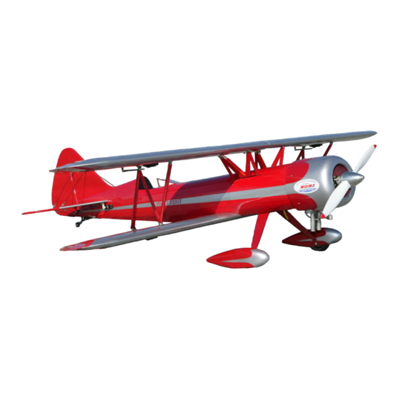
SUPER KRAFT
WACO UPF-7
Assembly Manual
KANGKE INDUSTRIAL USA Inc.
65 East Jefryn Blvd. Deer Park New York 11729
http://www.kangkeusa.com
E-mail:
info@kangkeusa.com
1-877-203-2377
Fax 1-631-274-3296
Warranty:
Kangke Industrial USA Inc. guarantees the kit to be free of defects in both
material and workmanship at the date of purchase. This warranty does not cover any parts
damaged by use or modifications. In no case shall Kangke Industrial's liability exceed the
purchase cost of this kit. Since Kangke Industrial has no control of final assembly and material
used by user for final assembly, no liability shall be assumed or accepted for any damage
resulting from the use by user of final use-assembled products. This kit has been flight tested
for normal use. If the plane will be used for extremely high stress flying, the modeler is
responsible for reinforcing the high stress points. Inspect this kit immediately after receiving it,
report any missing and damaged parts within 10 business days otherwise the claim may be
denied.
1
Advertisement

Summary of Contents for SUPER KRAFT WACO UPF-7
- Page 1 SUPER KRAFT WACO UPF-7 Assembly Manual KANGKE INDUSTRIAL USA Inc. 65 East Jefryn Blvd. Deer Park New York 11729 http://www.kangkeusa.com E-mail: info@kangkeusa.com 1-877-203-2377 Fax 1-631-274-3296 Warranty: Kangke Industrial USA Inc. guarantees the kit to be free of defects in both material and workmanship at the date of purchase.
-
Page 2: Super Kraft
Super Kraft 20% WACO UPF-7 Jimmy Franklin and his modified 1937 UPF-7 Waco bring the crowds to there feet at every air show he attends. His outstanding pilot abilities, jet-assisted performance and wing walking routine must be seen to be appreciated. - Page 3 WARNING! As model aircraft get larger and more powerful, the risk for injury increases. KANGKE’s extensive testing procedures insure a high quality kit that has gone through many steps to provide you with a safe reliable airframe. Nothing we can do however will make up for poor assembly or irresponsible behavior at the field.
- Page 4 The hardware for each step is packed 4) Install the upper wing “M” struts. in separate bags. The bag for the Note the front of the “M” is taller. landing gear contains the gear screws, axles and wheel pant screws; the bag short for the wings contains the strut mounts and all necessary hardware,...
- Page 5 11) Install the “N” struts in the same Label and remove the ailerons. manner as the “M” struts. Note the Install the Wing lock in the top wing. brackets will point in the opposite direction, on the lower wing they face out, on the upper they face in.
- Page 6 13) Assemble the tail wheel as shown. 16) Do not remove any covering material from the fin or stabilizer. Apply 30-miniute epoxy to the areas of the fin shown, as well as a small amount to the front and rear of the stabilizer through the fin slot in the Do not use CA fuselage (...
- Page 7 19) Bend eight flying wire brackets to 22) Install the lower flying wire a 45-degree angle. bracket at the front of the tail wheel bracket as shown. 20) Install 4 of the brackets on the fin, 23) Install the lower flying wires as the other four on the upper surface of was done with the top.
- Page 8 25) Place cowl in position, slide a ruler 29) Drill the cowl blocks only to 1/8- under the cowl to the mount block and inch, push the pieces of push rod into adjust the cowl so the dimension is the the holes flush with the surface of the same all the way around.
- Page 9 thrust has been built into the firewall, 35) For glow applications attach the this is the proper amount for the tank with a bead of silicone directly to smaller engines in the range, 1 ½ the hole in the firewall. Use the 3/8 X degrees works well with 150 size, and 3/8 balsa stock to support thee tank.
- Page 10 38) Install the anti-rotation screw in 41) There are several different control the wheel pants, followed by a washer configurations that can be used in the and lock nut. Place an axle screw in its Waco. Because of this no control rods hole to align the pant and tighten the are supplied and must be fabricated anti-rotation screw.
- Page 11 43) The control horns come in two supported at a point 4 ½-inches back lengths, short for ailerons and from the leading edge of the top wing, elevators and long for rudder pull- experiment for the best servo position pull. Locate the parts for a short horn. to balance.
- Page 12 Shown is the typical rudder servo and 48) Install the tail wheel control throttle servo mounted in the servo springs and bracket. Mount the tray. bracket 3-inches from the rudder hinge line. The tail wheel response may be tailored to your liking by cutting an equal number of coils from each spring in 1/4-inch increments.
-
Page 13: Motor Setup
Initial Control Settings: Rudder: 1.5” Right and Left Elevator: 1” Up and Down Ailerons: 5/8” Up and Down With the airframe assembled, check all nuts, screws and brackets are tight. Double check all controls move in the proper direction. MOTOR SET UP Be sure the motor is properly broken in using the manufacture instructions. - Page 14 Line up on the center of the runway and slowly open the throttle, using the rudder to maintain directional control. Once the tail is up apply a little up elevator and allow the plane to gently lift off the runway. Keep the climb angle and turns shallow until you reach a safe altitude.
-
Page 15: Advanced Flight Trim
ADVANCED FLIGHT TRIM All the following tests should be performed at 80% power unless noted. C.G. Fine Tuning: Roll inverted, neutral elevator to two clicks of down trim, if the model descends move the C.G. aft. If the model climbs move the C.G. forward. C.G.
Need help?
Do you have a question about the WACO UPF-7 and is the answer not in the manual?
Questions and answers