
Summary of Contents for VALMETAL 01A99-0200
- Page 1 SELF PROPELLED BEDDING CHOPPER MODEL 01A99-0200 OPERATOR’S MANUAL PARTS LIST 2009-07-01...
- Page 2 Valmetal’s choice of any parts found to be defective upon inspection by Valmetal. WARRANTY CLAIMS The purchaser claiming under this warranty shall submit a warranty claim in the prescribed form to Valmetal or an Authorized Dealer, for inspection by an authorized company representative.
- Page 3 SERIAL NUMBER LOCATION Always state the serial number of your Valmetal Self propelled bedding chopper when ordering parts or requesting service or other information. The serial number plate is located where indicated. Please mark the number in the space provided for easy reference.
-
Page 4: Table Of Contents
Contents SECTION 1 INTRODUCTION ..................SECTION 2 SAFETY ....................GENERAL SAFETY ........................OPERATING SAFETY ........................MAINTENANCE SAFETY ......................HYDRAULIC SAFETY ........................BATTERY SAFETY ........................TIRE SAFETY ..........................REFUELING SAFETY ........................STORAGE SAFETY ........................SAFETY DECALS ......................... 2.10 SIGN-OFF FORM ......................... SECTION 3 SAFETY DECALS LOCATION .............. -
Page 5: Section 1 Introduction
ValMetal. Keep this manual handy for frequent reference and to pass on to new operators or owners. Call your ValMetal Dealer or Distributor if you need assistance or information. OPERATOR ORIENTATION - The directions left, right, front and rear, as mentioned throughout this manual,... -
Page 6: Section 2 Safety
SECTION 2 SAFETY SAFETY ALERT SYMBOL This Safety Alert symbol means The Safety Alert symbol identifies important ATTENTION! BECOME ALERT! safety messages on the Valmetal Bedding YOUR SAFETY IS INVOLVED! chopper and in the manual. When you see this symbol, be alert to the possibility of per- sonal injury or death. -
Page 7: General Safety
GENERAL SAFETY YOU are responsible for the SAFE operation and 1 . Read and understand the Operator's Manual and maintenance of your ValMetal Self propelled bedding all safety signs before operating, maintaining or chopper. YOU must ensure that you and anyone... -
Page 8: Operating Safety
OPERATING SAFETY MAINTENANCE SAFETY 1. Read and understand the Operator's Manual and 1. Follow ALL the operating, maintenance and safe- all safety signs before operating, servicing, ty information in the manual. adjusting, repairing, unplugging or filling. Support the machine with blocks or safety stands when changing tires or working beneath it. -
Page 9: Hydraulic Safety
HYDRAULIC SAFETY TIRE SAFETY 1. Make sure that all components in the hydraulic 1. Failure to follow proper procedures when mount- system are kept in good condition and are clean. ing a tire on a wheel or rim can produce an explosion which may result in serious injury or 2. -
Page 10: Safety Decals
SAFETY DECALS 1. Keep safety decals and signs clean and readable at all times. 2. Replace safety decals and signs that are missing or have become illegible. 3. Replaced parts that displayed a safety sign should also display the current sign. 4. -
Page 11: Sign-Off Form
2.10 SIGN-OFF FORM ValMetal inc. follows the general Safety Standards specified by the Society of Automotive Engineers (SAE) and the Occupational Safety and Health Administration (OSHA). Anyone who will be operating and/or main- taining the Self propelled bedding chopper must read and clearly understand ALL Safety, Operating and Maintenance information presented in this manual. -
Page 12: Safety Decals Location
SECTION 3 SAFETY DECALS LOCATION The types of decals and locations on the equipment are shown in the illustration below. Good safety requires that you familiarize yourself with the various Safety Decals, the type of warning and the area, particular func- tion related to that area, that requires your SAFETY AWARENESS. - Page 13 The types of decals and locations on the equipment are shown in the illustration below. Good safety requires that you familiarize yourself with the various Safety Decals, the type of warning and the area, particular func- tion related to that area, that requires your SAFETY AWARENESS. Think SAFETY! Work SAFELY! REMEMBER - If Safety Decals have been damaged, removed, become illegible or parts replaced without decals, new decals must be applied.
-
Page 14: Operation
SECTION 4 OPERATION TO THE NEW OPERATOR OPERATING SAFETY OR OWNER It is the responsibility of the owner or operator to Read and understand the Operator's Manual and read this manual and to train all other operators all safety signs before operating, servicing, adjust- before they start working with the machine. -
Page 15: Machine Components
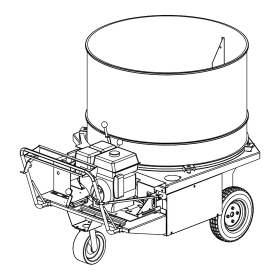
MACHINE COMPONENTS Grate Rotor (knives) Tub rotation control Grate height control Guide bar Direction/speed control Rotor drive control Outlet doors Hydraulic pump Oil tank Battery Fig. 1 Composantes principales... -
Page 16: Break-In
PRE-OPERATION CHECK LIST Although there are no operational restrictions on the machine when used for the first time, it is recom- Efficient and safe operation of the ValMetal Self pro- mended that the following mechanical items be pelled bedding chopper... -
Page 17: Controls
CONTROLS 3. Rotor Drive Control: The control lever to engage the rotor drive is located on the center of the frame under the guide bar. Move the lever All controls are conveniently positioned next to up to engage the rotor drive. Move the lever where the operator would stand when running the down to disengage the drive. - Page 18 C. Choke: Move the top sliding control to the left to close the choke for starting when engine is cold. Move the control to the right as engine warms to open choke. D. Throttle: Move the throttle to the right to run the engine at low RPM.
-
Page 19: Operating
OPERATING The Valmetal Self propelled bedding chopper can quickly and efficiently shred compacted bulk material to distribute and spred evenly over a surface. When using the machine, follow these procedures: IMPORTANT! New operators or people who have not operated the unit for a period of time should review the location and function of all controls before starting. - Page 20 12. Open a material outlet door (figure 12) 1/2 way and the other all the way open. Adjust them to give the required distribution pattern and cover- age. 13. Move the knife control lever up to engage the knife drive. 14.
-
Page 21: Storage
STORAGE 11. Block up the machine to take the load off the tires. If the unit is stored outside and exposed to sun- shine, it is recommended that the tires be removed and stored inside. STORAGE SAFETY 12. Disconnect the spark plug wire. 1. -
Page 22: Service And Maintenance
SECTION 5 SERVICE AND MAINTENANCE 5.1 SERVICE MAINTENANCE SAFETY 5.1.1 FUEL, FLUIDS AND LUBRICANTS 1. Follow ALL the operating, maintenance and safety information in the manual. 1. Grease Use an SAE multi-purpose high temperature The engagement / disengagement of the rotor grease with extreme pressure (EP) performance. -
Page 23: Servicing Intervals
5.1.3 SERVICING INTERVALS 8 hours or daily. 1. Check engine oil. Add if required. Fig. 14 Refueling Fig. 12 Engine oil level Wait 5 minutes to cool engine before refueling! A. Always use the proper container to refuel. 2. Clean the engine. Use a high-pressure air hose to blow the trash, dust and debris off the engine B. - Page 24 Monthly 4. Lubricate drive wheels flange bearings (2 loca- tions) and swivel wheel (figures 17 and 18). 1. Clean the air filter or change the oil in the engine air cleaner. Refer to engine manual for addition- al information. Change more frequently if work- ing conditions are very dusty.
-
Page 25: Service Record
5.1.4 SERVICE RECORD See Lubrication and Maintenance sections for details of service. Copy this page to continue record. ACTION CODE: CHECK CLEAN LUBRICATE CHANGE TIME: SERVICED BY: 8 HOURS OR DAILY Engine oil level Fuel level Air filter CL Engine MONTHLY CL Air filter Engine oil bath in air cleaner... -
Page 26: Maintenance
NOTE! Always use genuine ValMetal replacement parts to A clean engine runs better, stays cool and elimi- insure proper oil filtration. nates chances of fire. -
Page 27: Tub Rotation Drive
5.2.3 TUB ROTATION DRIVE 5.2.3.2 BELT REPLACEMENT To replace the belt, follow this procedure: 5.2.3.1 BELT TIGHTENING When the tub rotation drive is engaged, an idler is 1. Clear the area of bystanders, especially small moved into position to tighten the belt and transmit children. -
Page 28: Rotor Drive
Fig. 24 Grate control lever 5.2.4 ROTOR DRIVE Fig. 25 Rotor drive turnbuckle 5.2.4.1 BELTS TIGHTENING 5.2.4.2 BELTS REPLACEMENT When the rotor drive is engaged, an idler pulley is To replace the belts, follow this procedure moved into position to tighten the belts and transmit power. -
Page 29: Repairs
REPAIRS 5. Remove the 2 bolts securing the hinged cover to the main housing and flip over the hinged cover and tub to gain access to the rotor (fig. 27). IMPORTANT! During normal operation, the only component that normally will require replacement is the knife assem- bly on the shredding rotor. - Page 30 Replace with new original discs. IMPORTANT! Use only genuine ValMetal parts for all repairs to the machine. The rotor is made with special bal- anced knife discs and spacers. Non-genuine discs or knives might create excessive vibration and/or hit other parts of the machine.
- Page 31 Fig. 30 Reversing knives WARNING 1. Always wear heavy canvas or leather gloves when working with the knives on the rotor. 2. The knives are sharp and can give serious cuts. 3. Never use your hands to keep the rotor from turning.
-
Page 32: Section 6 Specifications
SECTION 6 SPECIFICATIONS BOLT TORQUE CHECKING BOLT TORQUE The tables shown below give correct torque values for various bolts and capscrews. Tighten all bolts to the torques specified in chart unless otherwise noted. Check tightness of bolts periodically, using bolt torque chart as a guide. - Page 33 SELF PROPELLED BEDDING CHOPPER MODEL 01A99-0200 PARTS LIST Self propelled bedding chopper Revised 2009-07-01...
- Page 34 FRAME REF. NO. PIÈCE DESCRIPTION REF. NO. PIÈCE DESCRIPTION 01A50-1751 Housing 99-368 Key 1/4’’ x 1 3/4’’ (included with item 15) 41-3B40-SH Pulley 3B40 x SH 19A55-0055 Axle coupler with scews 14C40-0008 Motor Honda 13 HP with electric. starter 40-UCFL207-20 Falnge bearing UCFL207 x 1 1/4 14C70-0096 Swivel wheel 10’’...
- Page 35 WHEELS DRIVE SYSTEM REF. PART NO. DESCRIPTION REF. PART NO. DESCRIPTION 01A50-1728 Guide bar 96-9365-08-06 Elbow 45 M-ORB / F-3/8”NPT 01A50-1733 Direction / speed lever 01A55-0088 Hydraulic hose M-3/8”NPT x 42” 01C17-0120 Hex. bolt 3/8” x 2 1/2” 96-3709-06 “T” female 3/8”NPT 01C67-0003 Tie rod end 3/8”-UNF 01A55-0089...
- Page 36 TUB DRIVE SYSTEM REF. PART NO. DESCRIPTION REF. PART NO. DESCRIPTION 17C46-0003 Idler pulley (including item 2) 01C45-0186 Hex. bolt M8 x 25 gr. 8.8 13C80-0061 Bushing 5/8” x 1/2” x 3/8” lg (included w/ bearing) 45-C40-20L Speed reducer C40-20L with keys 01A09-0100 Bushing 3/4”...
- Page 37 ROTOR DRIVE SYSTEM REF. PART NO. DESCRIPTION REF. PART NO. DESCRIPTION 01A50-0001 Rotor shaft 01A55-0037 Guard 01A11-3520 Spacer 2” x 11 GA x 1.310”lg 01C64-0232 Plastic knob 3/8”-UNC 01A55-0006 Knife disc assembly 01A50-0010 Standard cut grate (16 fingers) 26-021 Rotor shim 01A33-0035 Washer 1 1/4”...
- Page 38 VALMETAL INC. 230, BOUL. INDUSTRIEL ST-GERMAIN, QUÉBEC CANADA, J0C 1K0 TÉL: (819) 395-4282 FAX.: (819) 395-2030 www.valmetal.com info@valmetal.com IMPRIMÉ AU CANADA DATE DE PARUTION: 2009-07-01 NUMÉRO DE PIÈCE: 01A98-0055...
Need help?
Do you have a question about the 01A99-0200 and is the answer not in the manual?
Questions and answers