Advertisement

User Manual
1KVA/ 2KVA/ 3KVA
INVERTER / CHARGER

Advertisement

Table of Contents
loading

Summary of Contents for Luminous 1KVA

  • Page 1 User Manual 1KVA/ 2KVA/ 3KVA INVERTER / CHARGER...
  • Page 2: Table Of Contents

    CONTENTS ABOUT THIS MANUAL ............................. 1 Purpose ................................1 Scope ................................1 SAFETY INSTRUCTIONS ..........................1 INTRODUCTION ............................... 2 Features ................................2 Basic System Architecture
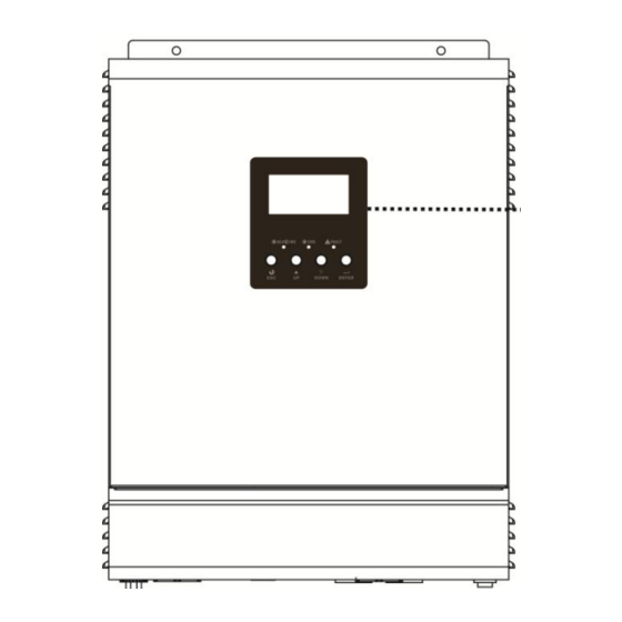
 ..........................2 Product Overview ............................. 3 INSTALLATION ..............................8 Unpacking and Inspection..........................8 Preparation ..............................8 Mounting the Unit .............................
  • Page 3: About This Manual

    Please strictly follow installation procedure when you want to disconnect AC or DC terminals. Please refer to INSTALLATION section of this manual for the details. 10. Fuses (40A, 32VDC *4pcs for 1KVA/2KVA and *6pcs for 3KVA) are provided as over-current protection for the battery supply.
  • Page 4: Introduction

    INTRODUCTION This is a multi-function inverter/charger, combining functions of inverter, solar charger and battery charger to offer uninterruptible power support with portable size. Its comprehensive LCD display offers user-configurable and easy-accessible button operation such as battery charging current, AC/solar charger priority, and acceptable input voltage based on different applications.
  • Page 5: Product Overview

    Otherwise, this inverter/charger will trig overload fault and cut off output to protect your appliance but sometimes it still causes internal damage to the air conditioner. Product Overview 2KVA/3KVA Model 1KVA Model 1. LCD display 2. Status indicator 3. Charging indicator 4.
  • Page 6 2) When solar source is not present, I =0, battery charged from utility source, I , load powered from utility, the Max. I limited at 20Amp for 1KVA, and 30Amp for 2KVA/3KVA. Utility Source Utility Charger DISC DC/AC Inverter...
  • Page 7 Priority Setting Combinations: Charger Priority Output Source Priority solar solar utility utility utility solar solar and utility utility solar and utility solar solar solar and utility 3) When utility and solar are presented, battery charged from solar source, I , load powered from solar and battery, the Max.
  • Page 8 5) When utility and solar are presented, battery charged from utility, I , load powered from utility, the Max. I limited at 20Amp for 1KVA, 30Amp 2KVA and 3KVA. Utility Source Utility Charger DISC DC/AC Inverter...
  • Page 9 7) When utility and solar are presented, battery charged from both solar and utility, I , load powered from solar and battery. If solar priority, output source turn to utility side in case solar panel without energy or battery voltage down to pre-alarm level. If sbu priority, output source turn to utility side in case of battery voltage down to pre setting level Ex.
  • Page 10: Installation

    INSTALLATION Unpacking and Inspection Before installation, please inspect the unit. Be sure that nothing inside the package is damaged. You should have received the following items inside of package:  The unit x 1  User’s manual x 1  Communication cable x 1 Preparation Before connecting all wirings, please take off bottom cover by removing two screws as shown below.
  • Page 11: Battery Connection

    1. Assemble battery ring terminal based on recommended battery cable and terminal size. 2. 1KVA model supports 12VDC system and 2KVA/3KVA model supports 24VDC system. Connect all battery packs as below chart. It’s suggested to connect at least 100Ah capacity battery for each.
  • Page 12: Ac Input/Output Connection

    Please follow below steps to implement AC input/output connection: 1. Before making AC input/output connection, be sure to open DC protector or disconnector first. 2. Remove insulation sleeve 6mm for six conductors of 1KVA and 10mm for 2K/3KVA. And shorten phase L and neutral conductor N 3 mm.
  • Page 13: Pv Connection (Only Apply For The Model With Solar Charger)

    ) first. L→LINE (brown or black) →Ground (yellow-green) N→Neutral (blue) 1KVA 2KVA/3KVA 5. Make sure the wires are securely connected. PV Connection (Only apply for the model with solar charger) CAUTION: Before connecting to PV modules, please install separately a DC circuit breaker between inverter and PV modules.
  • Page 14: Final Assembly

    Please follow below steps to implement PV module connection: 1. Remove insulation sleeve 10 mm for positive and negative conductors. 2. Check correct polarity of connection cable from PV modules and PV input connectors. Then, connect positive pole (+) of connection cable to positive pole (+) of PV input connector.
  • Page 15: Operation

    OPERATION Power ON/OFF Once the unit has been properly installed and the batteries are connected well, simply press On/Off switch (located on the button of the case) to turn on the unit. Operation and Display Panel The operation and display panel, shown in below chart, is on the front panel of the inverter. It includes three indicators, four function keys and a LCD display, indicating the operating status and input/output power information.
  • Page 16: Lcd Display Icons

    LCD Display Icons Icon Function description Input Source Information Indicates the AC input. Indicates the PV input Indicate input voltage, input frequency, PV voltage, battery voltage and charger current. Configuration Program and Fault Information Indicates the setting programs. Indicates the warning and fault codes. Warning: flashing with warning code.
  • Page 17 In battery mode, it will present battery capacity. Load Percentage Battery Voltage LCD Display < 1.717V/cell 1.717V/cell ~ 1.8V/cell Load >50% 1.8 ~ 1.883V/cell > 1.883 V/cell < 1.817V/cell 1.817V/cell ~ 1.9V/cell 50%> Load > 20% 1.9 ~ 1.983V/cell > 1.983 <...
  • Page 18: Lcd Setting

    LCD Setting After pressing and holding ENTER button for 3 seconds, the unit will enter setting mode. Press “UP” or “DOWN” button to select setting programs. And then, press “ENTER” button to confirm the selection or ESC button to exit. Setting Programs: Program Description...
  • Page 19 11.0V: 11.3V: 11.5V(default): 11.8V: 12.0V: 12.3V: 12.5V: 12.8V: Above setting effective in 1kVA model Pre setting voltage back to utility side for sbu priority 22.0V: 22.5V: 23.0V(default): 23.5V: 24.0V: 24.5V: 25.0V: 25.5V: Above setting effective in 2kVA/3kVA model Solar first:...
  • Page 20: Display Setting

    Alarm on(default): Alarm off: Beeps while primary source is interrupted Record enable: Record disable(default): Record Fault code Display Setting The LCD display information will be switched in turns by pressing “UP” or “DOWN” key. The selectable information is switched as below order: input voltage, input frequency, battery voltage, PV voltage, charging current, output voltage and load in Watt.
  • Page 21 Current ≧ 10A Charging current/Output voltage Current < 10A When load is lower than 1kVA, load in VA will presents 350V as below. Input voltage/Load in VA When load is larger than 1kVA (≧1KVA), load in VA will presents 1.5kVA as below:...
  • Page 22: Operating Mode Description

    Secondary CPU version 00003.03 Secondary CPU version checking Operating Mode Description Operation mode Description LCD display Charging by utility and PV Charging by utility No output is supplied by the Standby mode/ Fault mode/ unit but it still can charge Power saving mode batteries.
  • Page 23: Fault Reference Code

    Fault Reference Code Fault Code Fault Event Icon on Fan is locked Over temperature Battery voltage is too high Battery voltage is too low Output short circuited or Over temperature Output voltage is abnormal Over load time out Bus voltage is too high Bus soft start failed Main relay failed Warning Indicator...
  • Page 24: Specifications

    SPECIFICATIONS Table 1 Line Mode Specifications INVERTER MODEL 1KVA 2KVA 3KVA Input Voltage Waveform Sinusoidal (utility or generator) Nominal Input Voltage 230Vac 170Vac± 7V (UPS); Low Loss Voltage 90Vac± 7V (Appliances) 180Vac± 7V (UPS); Low Loss Return Voltage 100Vac± 7V (Appliances) High Loss Voltage 280Vac±...
  • Page 25: Table 2 Invert Mode Specifications

    Table 2 Invert Mode Specifications INVERTER MODEL 1KVA 2KVA 3KVA 1KVA/0.8KW 2KVA/1.6KW 3KVA/2.4KW Rated Output Power Pure Sine Wave Output Voltage Waveform 230Vac± 5% Output Voltage Regulation 50Hz Output Frequency Peak Efficiency Overload Protection 5s@≥150% load; 10s@110%~150% load 2* rated power for 5 seconds...
  • Page 26: Charging Controls

    Table 3 Charge Mode Specifications INVERTER MODEL 1KVA 2KVA 3KVA Charging Algorithm 3-Step Utility Charging Mode Charging Current (UPS) 10/20Amp 20/30Amp (@V =230Vac) Charging Floating Voltage 13.5Vdc 27Vdc Solar Charging Mode Charging Current (PWM) 50Amp System DC Voltage 12Vdc 24Vdc Max.
  • Page 27: Trouble Shooting

    TROUBLE SHOOTING Problem LCD/LED/Buzzer Explanation / Possible cause What to do Unit shuts down LCD/LEDs and buzzer automatically will be active for 3 The battery voltage is too low 1. Re-charge battery. during startup seconds and then (<1.91V/Cell) 2. Replace battery. process.
  • Page 28: Appendix: Approximate Back-Up Time Table

    Appendix: Approximate Back-up Time Table Model Load (VA) Backup Time @ 12Vdc 100Ah (min) Backup Time @ 12Vdc 200Ah (min) 1610 1KVA 1000 Model Load (VA) Backup Time @ 24Vdc 100Ah (min) Backup Time @ 24Vdc 200Ah (min) 1610 1000...

This manual is also suitable for:

2kva3kva

Table of Contents