
Related Manuals for Rosemount 54E

Summary of Contents for Rosemount 54E
- Page 1 Instruction Manual 510054EpH Model 54e pH/ORP February 2001 ® pH/ORP HART Analyzer/Controller...
- Page 2 ELECTRICAL SHOCK HAZARD READ THIS PAGE BEFORE PROCEEDING! Making cable connections to and servicing this Rosemount Analytical designs, manufactures, and tests instrument require access to shock hazard level its products to meet many national and international stan- voltages which can cause death or serious dards.
-
Page 4: Table Of Contents
MODEL 54e pH/ORP TABLE OF CONTENTS MODEL 54E PH/ORP MICROPROCESSOR ANALYZER TABLE OF CONTENTS Section Title Page DESCRIPTION AND SPECIFICATIONS ..............General Description ....................Description of Controls.................... Specifications ......................Ordering Information ....................INSTALLATION ....................... Locating the Controller .................... Unpacking and Inspection .................. - Page 5 MODEL 54e pH/ORP TABLE OF CONTENTS TABLE OF CONTENTS (CONTINUED) Section Title Page THEORY OF OPERATION..................The pH Sensor Assembly..................Continuous Sensor Diagnostics ................Interval Timer......................Alarm Relays ......................Time Proportional Control (TPC) Mode ..............Normal Mode......................Analog Outputs .......................
- Page 6 Page Main Display Screen................Wall Mounting ..................Pipe Mounting ..................Panel Mounting..................Power Input and Relay Output Wiring for Model 54e pH/ORP..... Sensor Wiring Photo ................Sensor Wiring Diagram ................ Cable Dressing..................Wiring for Sensors that have Solution Grounds........Wiring for Sensors without Solution Grounds Directly to Analyzer ..
-
Page 7: Description And Specifications
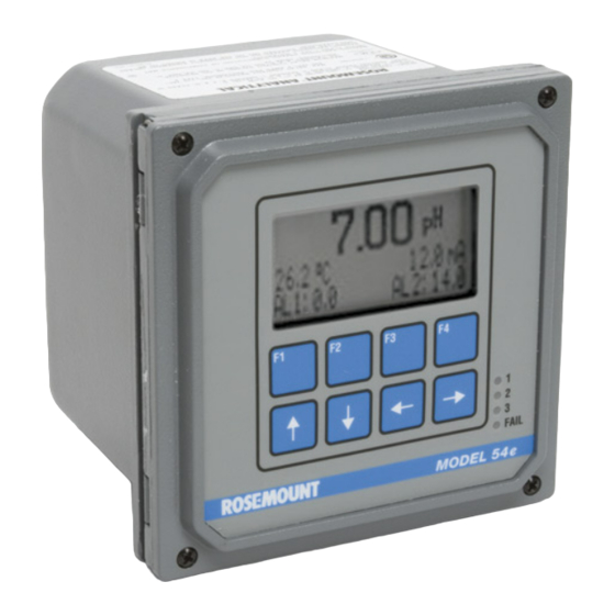
The F1-F4 keys are multifunction. The active opera- tion for that key is displayed as a label just above The Model 54e pH/ORP analyzer/controller monitors each function key as needed. For example, F1 is and controls pH in chemical processes used in many usually labeled Exit and F4 may be labeled Edit, industries. -
Page 8: Specifications
MODEL 54e pH/ORP SECTION 1.0 DESCRIPTION AND SPECIFICATIONS 1.3 SPECIFICATIONS PHYSICAL SPECIFICATIONS - GENERAL Enclosure: Epoxy-painted aluminum, NEMA 4X (IP65), 144 X 144 X 132 mm, DIN size (5.7 X 5.7 X 5.2 in.) Front Panel: Membrane keyboard with tactile feedback and user selectable security. Light gray, blue and white overlay. - Page 9 4.5 meters (15 feet) or less. ANALYZER SPECIFICATIONS @ 25°C The Model 54e pH measures over the full range of 0- 14 pH. The current output may be calibrated to repre- Measurement Range: –1400 to +1400 mV sent any 1 to 14 pH span.
-
Page 10: Ordering Information
DESCRIPTION AND SPECIFICATIONS 1.4 ORDERING INFORMATION The Model 54e pH/ORP Microprocessor Analyzer is housed in a rugged, NEMA 4X (IP65) epoxy- painted cast aluminum enclosure. Standard features include a back-lit dot-matrix liquid crystal display, sensor diagnostics, dual isolated outputs, and four relays. The analyzer can measure pH or ORP as configured by the user. For ISE capability, please consult the factory. -
Page 11: Installation
2.1 LOCATING THE CONTROLLER Position the Model 54e pH/ORP controller to minimize the effects of temperature extremes and to avoid vibration and shock. Locate the controller away from your chemical process to protect it from moisture and fumes. -
Page 12: Panel Mounting
MODEL 54e pH/ORP SECTION 2.0 INSTALLATION 2.3.4 Panel Mounting: The controller is designed to fit into a 5.7 x 5.7 inch (DIN standard 144x144 mm) panel cutout (Figure 2-3). Installation requires both front and rear access. 1. Install the controller as shown in Figure 2-3. Insert the instrument enclosure through the front of the panel cutout and align the panel mounting brackets as shown. -
Page 13: Wiring
The controller has 3 "dry" alarm relay contacts which are normally open. Alarm 1 is across terminals 4 and 5 on The Model 54e pH/ORP has five access holes in the bot- TB3. This alarm is typically used to control the pump in a tom of the instrument housing which accept ½-in. -
Page 14: Power Input And Relay Output Wiring For Model 54E Ph/Orp
MODEL 54e pH/ORP SECTION 3.0 WIRING DWG. NO. REV. 454EPH02 FIGURE 3-1. Power Input and Relay Output Wiring for Model 54e pH/ORP... -
Page 15: Ph Sensor Wiring
The wiring diagrams show connections between sensor (or j-box) has a preamp, then the preamp loca- the Model 54e pH/ORP and the junction box used tion jumper is moved accordingly and wiring connected where distance from the sensor to the controller as on the left of Figure 3-3. -
Page 16: Sensor Wiring Diagram
MODEL 54e pH/ORP SECTION 3.0 WIRING DWG. NO. REV. 454EPH01 FIGURE 3-3. Sensor Wiring Diagram... -
Page 17: Cable Dressing
MODEL 54e pH/ORP SECTION 3.0 WIRING To prepare the cable for sensor wiring: 1. Use only the cable specified. Figure 3-4 shows the 10 conductor cable with 3 shields (9200273). 2. Strip back the PVC jacket 4 in. or far enough... -
Page 18: Final Electrical Check
MODEL 54e pH/ORP SECTION 3.0 WIRING FIGURE 3-6. Wiring for Sensors Without Solution Grounds Directly to Analyzer (Models 389-02-54, 396- 54, 397-54, 399-09). For wiring to a junction box, see Figure 3-7. FIGURE 3-7. Wiring for Sensors Without Solution Grounds to a Junction Box (Models 389-02-54, 396-54, 399-09) NOTES: Interconnecting wire maximum length is 500 ft. -
Page 19: Calibration
Since pH measurements are affected by temperature, signs of leakage or wear. the Model 54e pH/ORP reads the temperature at the sensor and compensates for the changing temperature by referencing all pH measurements to 25°C (77 °F). -
Page 20: Temperature Calibration
MODEL 54e pH/ORP SECTION 4.0 CALIBRATION 4.1 TEMPERATURE CALIBRATION This procedure is used to ensure an accurate temperature measurement by the temperature sensor. It enables the controller to display process temperature accurately as well as to compensate for the effect of tem- perature on the pH reading when the temperature in your process changes. -
Page 21: Automatic Two-Point Calibration
MODEL 54e pH/ORP SECTION 4.0 CALIBRATION 4.2 AUTOMATIC TWO-POINT CALIBRATION The two-point calibration is performed when the controller is initially installed and whenever elements of the sensor assembly or controller are replaced. The two-point calibration re-establishes the slope of the elec- trode. - Page 22 MODEL 54e pH/ORP SECTION 4.0 CALIBRATION 3. A screen like the one on the left will appear after stabilization. 4.02 Use the arrow keys to select the correct buffer. If the correct buffer does not appear, refer to Section 5.9 and select a Buf1 done: 4.01...
-
Page 23: Manual Two-Point Calibration
MODEL 54e pH/ORP SECTION 4.0 CALIBRATION 4.3 MANUAL TWO-POINT CALIBRATION This procedure is followed if Autocal is set to "Manual" in Section 5.9. 2-pt calibration Buffer values are entered manually and no stabilization check is used. 1. From the main display, press any key to obtain the main menu. With Standardize pH the cursor on "Calibrate", press Enter (F4). -
Page 24: Single-Point Ph Calibration
This value can then be entered into the Model 54e pH/ORP to make it agree with the lab instru- ment. Many processes have effects on on-line sensors that cause them to read slightly different than grab samples measured with laboratory electrodes. -
Page 25: Compensation Options
MODEL 54e pH/ORP SECTION 4.0 CALIBRATION 4.5 TEMPERATURE COMPENSATION OPTIONS Automatic Temperature Compensation is a standard option for pH equip- Adjust temperature ment and is used in virtually all pH measurement situations. If compen- sation is not desired, the temperature signal from the sensor can be... -
Page 26: Hold Mode
MODEL 54e pH/ORP SECTION 4.0 CALIBRATION 4.7 HOLD MODE Placing the Controller on Hold for Maintenance. Before performing main- 7.00 tenance or repair of the sensor, the Controller can be placed in hold (refer to Section 5.6 to enable this feature) to prevent process upsets while the reading is off-line. -
Page 27: Software Configuration
MODEL 54e pH/ORP SECTION 5.0 SOFTWARE CONFIGURATION SECTION 5.0 SOFTWARE CONFIGURATION This section contains the following: • An introduction to using the configuration process • A List of Settings for the controller • Step-by-step instructions and explanations for each parameter on the List INTRODUCTION TO CONFIGURATION The controller arrives from the factory configured and ready to operate as a pH controller. - Page 28 MODEL 54e pH/ORP SECTION 5.0 SOFTWARE CONFIGURATION TABLE 5-1. pH Settings List (continued) ITEM RANGES FACTORY SETTINGS USER SETTINGS 2b. Output 1 Setup (PID) (a) Setpoint -2 to 16 pH or -15 to 130°C 7 pH _______ (b) Proportional 0-299.9% 100.0%...
- Page 29 _______ By changing the standard output configuration, you can set up the Model 54e pH/ORP to perform a wide variety of control and monitoring tasks. The configuration procedures allow you to program the controller to meet the specific control and monitoring requirements of your particular plant.
-
Page 30: Outline Of Menu Levels
MODEL 54e pH/ORP SECTION 5.0 SOFTWARE CONFIGURATION Accessing Calibrate, Program and Configure Level 2 Program. To access the program level from Menus. Operating configuration changes are made the main menu, place the cursor over "Program" with at the levels shown in Figure 5-1. Pressing any key the down arrow key. -
Page 31: Changing Alarm Setpoints
MODEL 54e pH/ORP SECTION 5.0 SOFTWARE CONFIGURATION 5.1 CHANGING ALARM SETPOINTS This section describes how the three alarm setpoints can be changed. Alarm setpoints Move the cursor down by pressing the arrow key. Output setpoints 1. From the main menu, move the cursor down to "Program" and press Simulate tests Enter (F4). -
Page 32: Changing Output Setpoints (Pid Only)
MODEL 54e pH/ORP SECTION 5.0 SOFTWARE CONFIGURATION 5.2 CHANGING OUTPUT SETPOINTS (PID ONLY) This section describes how the two output setpoints can be changed. Alarm setpoints This selection is only active if the current output control mode has been set to "PID" (see Section 5.6). If the control mode is set to "normal", then Output setpoints "Not applicable"... -
Page 33: Changing Output Setpoints (Normal)
MODEL 54e pH/ORP SECTION 5.0 SOFTWARE CONFIGURATION 5.3 CHANGING OUTPUT SETPOINTS (NORMAL ONLY) This section describes how the 4 (or 0) to 20 mA current outputs can be Alarm setpoints reranged. Note that the current outputs can be configured to represent pH, temperature, glass impedance, or reference impedance. -
Page 34: Testing Outputs And Alarms
MODEL 54e pH/ORP SECTION 5.0 SOFTWARE CONFIGURATION 5.4 TESTING OUTPUTS AND ALARMS This section describes how the current outputs and alarm relays can be Alarm setpoints manually set for the purposes of checking devices such as valves, pumps, or recorders. - Page 35 MODEL 54e pH/ORP SECTION 5.0 SOFTWARE CONFIGURATION 5.4 TESTING OUTPUTS AND ALARMS (continued) 3b. The alarm relay is now being simulated. In the example to the left, Test alarm 1: Open alarm 1 has been set to Open. This means that the relay is not ener- gized (i.e.
-
Page 36: Choosing Display Options
MODEL 54e pH/ORP SECTION 5.0 SOFTWARE CONFIGURATION 5.5 CHOOSING DISPLAY OPTIONS This section describes the options available for the changing of engineering Display units and variables on the main display. 1. From the main menu, move the cursor down to "Program" and press Outputs Enter ". - Page 37 MODEL 54e pH/ORP SECTION 5.0 SOFTWARE CONFIGURATION 5.5 CHOOSING DISPLAY OPTIONS (CONTINUED) 4. This screen allows you to choose the items displayed on the third line Display left: left and right of the main display screen. The process temperature and output 1 value (in mA or %) are always shown on line 2 of the Display right: main display.
-
Page 38: Changing Output Parameters
MODEL 54e pH/ORP SECTION 5.0 SOFTWARE CONFIGURATION 5.6 CHANGING OUTPUT PARAMETERS This section describes the options available for configuration of the out- Display puts. Each output can be configured to represent pH (or ORP/Redox, see Appendix A), temperature, glass impedance, or reference impedance. In Outputs addition, each output can be linear (normal) or nonlinear (PID). - Page 39 MODEL 54e pH/ORP SECTION 5.0 SOFTWARE CONFIGURATION 5.6 CHANGING OUTPUT PARAMETERS (continued) Menu Item Options Output Setup Parameters Range 4-20mA/0-20mA (for Normal Outputs) Dampen(ing) 0-299 sec Hold Last value/fixed value Range: 4-20 mAl Fixed Hold (if Output 1 hold is "fixed value") 0-22.00 mA...
- Page 40 MODEL 54e pH/ORP SECTION 5.0 SOFTWARE CONFIGURATION 5.6 CHANGING OUTPUT PARAMETERS (continued) "Proportional" is short for Proportional Band and indicates the range over which control is being used. It is the opposite of the process gain. Smaller values provide tighter control.
-
Page 41: Changing Alarm Parameters
MODEL 54e pH/ORP SECTION 5.0 SOFTWARE CONFIGURATION 5.7 CHANGING ALARM PARAMETERS This section describes the options available for configuration of the Outputs alarms. Alarms 1, 2, and 3 can be activated on pH (or ORP/Redox, see Appendix A), or temperature. One of these alarms can be setup as a feed Alarms limit timer and another alarm can be dedicated as an interval timer. - Page 42 MODEL 54e pH/ORP SECTION 5.0 SOFTWARE CONFIGURATION 5.7 CHANGING ALARM PARAMETERS (continued) Menu Item Options Alarm Control Parameters Activation Method Process/Temperature Control Mode Normal/TPC Activation Method Control Mode Alarms 1, 2, and 3 can each be configured with the options above.
- Page 43 MODEL 54e pH/ORP SECTION 5.0 SOFTWARE CONFIGURATION 5.7 CHANGING ALARM PARAMETERS (continued) Menu Item Options Alarm Setup Parameters (for TPC Alarms) Set point -2 to 20 pH, -1400 to +1400 mV(ORP/Redox) Proportional 0-299.9 % Integral 0-2999 sec Setpoint: +07.00 pH Derivative 0-299.9 %...
- Page 44 MODEL 54e pH/ORP SECTION 5.0 SOFTWARE CONFIGURATION 5.7 CHANGING ALARM PARAMETERS (continued) CAUTION Understanding where to set the TPC parameters is not trivial and is likely to require substantial trial and error to yield acceptable results. pH and ORP/Redox are nonlin- ear measurements and applying PID algorithms can result in unintended effects.
- Page 45 MODEL 54e pH/ORP SECTION 5.0 SOFTWARE CONFIGURATION 5.7 CHANGING ALARM PARAMETERS (continued) Interval Timer Setup Menu Item Options Timer (enable) Disable/AL1/AL2/AL3 Interval 0-999.9 hr Timer: Disable Repeats 1-60 Timer: Time activated On time 1-2999 sec Interval: 24.0 hr Off time...
-
Page 46: Interval Timer Examples
MODEL 54e pH/ORP SECTION 5.0 SOFTWARE CONFIGURATION 5.7 CHANGING ALARM PARAMETERS (continued) “On” “On” Time Time (sec) (sec) RELAY RELAY ACTIVATION ACTIVATION Interval Recovery Interval Recovery (hr) (sec) (hr) “Off” (sec) Time (sec) TIME TIME Sequence A: One repeat per cycle Sequence B: Two repeats per cycle FIGURE 5-2. -
Page 47: On-Line Diagnostics Setup
MODEL 54e pH/ORP SECTION 5.0 SOFTWARE CONFIGURATION 5.8 ON-LINE DIAGNOSTICS SETUP This section describes the options available for configuration of the on- Alarms line sensor diagnostics. The controller checks the integrity of the glass electrode (for pH only) and the reference electrode by continuously meas- Diagnostics uring the impedance of each. -
Page 48: Auto Calibration Setup
MODEL 54e pH/ORP SECTION 5.0 SOFTWARE CONFIGURATION 5.8 ON-LINE DIAGNOSTICS SETUP (continued) "Cal warn" compares the on-line glass impedance with the value meas- ured at the last buffer calibration. This setting should be set to 0 (dis- abled). "Imped comp" is used to compensate the glass impedance for tempera- ture changes. - Page 49 MODEL 54e pH/ORP SECTION 5.0 SOFTWARE CONFIGURATION 5.9 AUTO CALIBRATION SETUP (continued) TABLE 5-2. Standard Buffers Buffer Value @ 25°C Standards Referenced Buffer Composition Factory Configured 1.68 NIST, DIN 19266, JIS 8802 0.05M K tetroxalate 3.56 NIST, BSM KH tartrate (sat’d @ 25°C) 3.78...
-
Page 50: Theory Of Operation
7. This compensation on the electrode changes, creating a change in poten- is done automatically by the Model 54e pH/ORP unless tial on the glass electrode. specifically disabled. -
Page 51: Interval Timer
MODEL 54e pH/ORP SECTION 6.0 THEORY OF OPERATION A new glass electrode has an impedance of approxi- 6.3 INTERVAL TIMER mately 200 megohms As it ages, this value typically The interval timer may be used for periodic sensor increases over time because lithium ions (which carry... -
Page 52: Alarm Relays
See Section 5.7 "Alarms" to program the alarm relays. The Model 54e pH/ORP has two control modes for de- vices which are turned off and on: Time Proportional Control Mode (TPC), and Normal Mode. TPC is gener- ally used for chemical feed control. -
Page 53: Normal Mode
URV value will be below the LRV (i.e. below The Model 54e pH/ORP is connected to a strip chart zero). As the pH rises toward the control point value, recorder with a 0 to 100% scale. -
Page 54: Controller Mode Priority
SECTION 6.0 THEORY OF OPERATION CONTROLLER MODE PRIORITY Your Model 54e pH/ORP can function in different modes Priority is in the following order (from lowest to highest): depending on both how it is configured, what process normal, fault, timer, hold, feed limit, test. Each output or conditions exist, and actions an operator may have made. -
Page 55: Pid Control
PID CONTROL (CODE -20) PID Control Measurement and Set Point (Feedback Control) The Model 54e pH/ORP current outputs can be pro- The Model 54e pH/ORP controller is given two items grammed for PID control. PID control is used with a of information: measurement and set point. - Page 56 The controller configured with reset continues to duce the output. change until there is no offset. If the offset persists, the The Model 54e pH/ORP's proportional mode is reset action eventually drives the controller output to its referred to as proportional "band" which is config- 100% limit - a condition known as "reset windup".
-
Page 57: The Process Reaction Curve
3. Using the simulate test, manually set the controller To use this procedure with a Model 54e pH/ORP and a output signal at the value which represented the control valve or metering pump, follow the steps out- stable process measurement observed in step 1, lined below. - Page 58 In the example shown in Figure 6-2: overall dynamics of the system. It will be used to calcu- The percent change in pH was: late the needed tuning parameters of the Model 54e pH/ORP controller. pH2 - pH1 8.2 - 7.2 pH...
-
Page 59: Special Procedures And Features
Section 5.0. A Level 2 user can do all of the above and: As with all the settings in your Model 54e pH/ORP, the 1. Change control setpoints for PID current outputs first step to configuration is obtaining a good under- (Section 5.1). -
Page 60: Configuring Security
MODEL 54e pH/ORP SECTION 7.0 SPECIAL PROCEDURES AND FEATURES 7.2 CONFIGURING SECURITY Security clearance is required at the following security "gates". Users Alarms without the security code will only be able to use the features indicated in parentheses: Security Lock out all access (read main screen only) Custom Curve II. -
Page 61: Solution Temperature Compensation
MODEL 54e pH/ORP SECTION 7.0 SPECIAL PROCEDURES AND FEATURES 7.3 SOLUTION TEMPERATURE COMPENSATION This section is for advanced users only. Security It explains how to input values for: Temperature Coeff o the isopotential pH and Temperature sensor o the temperature coefficient for solution temperature compensation. - Page 62 MODEL 54e pH/ORP SECTION 7.0 SPECIAL PROCEDURES AND FEATURES 7.3 SOLUTION TEMPERATURE COMPENSATION (continued) Menu Item Options Temp coeff: +.000 Temperature coefficient -0.044 to 0.028 pH/°C (0.00 for most applications) Operate iso: +07.00 pH Operating isopotential -1.35 to 20.12 pH (7.00 for most Sensor iso: 07.00 pH...
-
Page 63: Troubleshooting
SECTION 8.0 TROUBLESHOOTING SECTION 8.0 TROUBLESHOOTING The Model 54e pH/ORP automatically searches for Many control problems are unrelated to the conductiv- fault conditions that would cause an error in the meas- ity measurement system. When problems arise, first ured pH reading. If such a condition occurs, the current... - Page 64 "Sensor line open" 1. Open wire between sensor and controller. 2. Distance between sensor and controller is too long. "Failure - EEPROM" 1. Defective CPU board. Notify Rosemount "Failure - CPU" if cycling power does not clear the fault "Failure - Factory"...
- Page 65 MODEL 54e pH/ORP SECTION 8.0 TROUBLESHOOTING TABLE 8-2. Quick Troubleshooting Guide SYMPTOM ACTION pH reading won't change in different buffers. Clean the electrode, check wiring. Replace electrode. "Cracked glass failure". 1. Replace electrode if cracked. 2. Check wiring for short.
-
Page 66: Displaying Diagnostic Variables
MODEL 54e pH/ORP SECTION 8.0 TROUBLESHOOTING 8.1 DISPLAYING DIAGNOSTIC VARIABLES This section explains how these helpful diagnostics can be viewed: 1. Electrode input in mV: Used to check if the signal produced by the sensor is within acceptable limits (see Figure 8-1 for typical sensor mV response at 25°C). -
Page 67: Theoretical Ph Vs. Millivolt Values At 25°C (77°F)
MODEL 54e pH/ORP SECTION 8.0 TROUBLESHOOTING FIGURE 8-1. Theoretical pH vs. Millivolt Values at 25°C (77°F) -
Page 68: Troubleshooting Guidelines
MODEL 54e pH/ORP SECTION 8.0 TROUBLESHOOTING 8.2 TROUBLESHOOTING GUIDELINES NOTE TEMPERATURE COMPENSATION CIRCUIT To clear any Fault message, press the Troubleshooting Procedure key. Use this procedure to diagnose problems in the tem- perature compensation circuit or as directed by the If no specific error message is being displayed, the fol- Troubleshooting Guide, Table 8-3. - Page 69 MODEL 54e pH/ORP SECTION 8.0 TROUBLESHOOTING B. Controller preamp check (Figure 8-3) PREAMPLIFIER TROUBLESHOOTING PROCEDURE 1. Disconnect all sensor wiring from the controller at TB2. Use this procedure when diagnosing the circuit which carries the signal from the sensor. There are 3 sepa- 2.
-
Page 70: Junction Box Preamplifier Check
MODEL 54e pH/ORP SECTION 8.0 TROUBLESHOOTING FIGURE 8-2. Junction Box Preamplifier Check FIGURE 8-3. Controller Preamplifier Check... - Page 71 MODEL 54e pH/ORP SECTION 8.0 TROUBLESHOOTING TABLE 8-3. Troubleshooting Guide PROBLEM OR CONDITION PROBABLE CAUSE AND FOR MORE HELP, CORRECTIVE ACTION REFER TO Controller completely inoperative No Power - Wiring, Section 3.0 and Figure 3-1 Check power supply at breaker and inside controller: 115 V across terminals 1 and 2 on TB3.
- Page 72 MODEL 54e pH/ORP SECTION 8.0 TROUBLESHOOTING TABLE 8-3. Troubleshooting Guide (continued) PROBLEM OR CONDITION PROBABLE CAUSE AND FOR MORE HELP, CORRECTIVE ACTION REFER TO Controller "short spans." Coated glass electrode - Buffer check with 2-point Clean with soft cloth calibration gives slope less and clean water.
- Page 73 MODEL 54e pH/ORP SECTION 8.0 TROUBLESHOOTING TABLE 8-3. Troubleshooting Guide (continued) PROBLEM OR CONDITION PROBABLE CAUSE AND FOR MORE HELP, CORRECTIVE ACTION REFER TO Display reads between 3 and Electrode cracked - 6 pH regardless of actual pH Replace electrode.
-
Page 74: Replacement Parts
MODEL 54e pH/ORP SECTION 8.0 TROUBLESHOOTING 8.3 REPLACEMENT PARTS PART NUMBER DESCRIPTION 23540-05 Enclosure, Front with Keyboard 23824-01 PCB, 115/230 Vac Power Supply, CE, (Code -01) 23848-00 Power Supply Circuit Board Shield 23849-00 Half Shield, Power Supply 23854-00 PCB, CPU for Back-lit Display... -
Page 75: Return Of Materials
9.2 WARRANTY REPAIR. The following is the procedure for returning instruments still under warranty: Call Rosemount Analytical for authorization. To verify warranty, supply the factory sales order number or the original purchase order number. In the case of individual parts or sub-assemblies, the serial number on the unit must be supplied. -
Page 76: A Orp Configuration
ORP CONFIGURATION QUICK STARTUP (ORP) CONFIGURING THE CONTROLLER The Model 54e pH/ORP controller comes pre-pro- Configuration of the ORP settings can be done at any grammed by the factory as a pH controller. In order to time after the controller has been set to ORP mode perform a quick startup as an ORP controller, the (step 3 in Quick Startup on the left). -
Page 77: A-1 Orp Settings List
MODEL 54e pH/ORP APPENDIX A ORP CONFIGURATION TABLE A-1. ORP Settings List ITEM CHOICES ORP SETTINGS USER SETTINGS PROGRAM LEVEL (Sections A.2 - A.3) Alarm Setpoints (Section A.2) Alarm 1 (low action) -1400 to +1400 mV -1400 mV _______ Alarm 2 (high action) - Page 78 MODEL 54e pH/ORP APPENDIX A ORP CONFIGURATION TABLE A-1. ORP Settings List ITEM CHOICES ORP SETTINGS USER SETTINGS Alarm 1 Setup (a) Configuration Low alarm/High alarm/Off _______ (b) Hysteresis (deadband) 0-500 mV 0 mV _______ (c) Delay Time 0-99 sec...
-
Page 79: Outline Of Menu Levels For Orp
MODEL 54e pH/ORP APPENDIX A ORP CONFIGURATION Accessing Calibrate, Program and Configure Level 2 Program. To access the program level from Menus. Operating configuration changes are made at the main menu, place the cursor over "Program" with the levels shown in Figure A-1. Press any key from the down arrow key. - Page 80 MODEL 54e pH/ORP APPENDIX A ORP CONFIGURATION A.1 ORP CALIBRATION ORP Calibration consists of a single standardize adjustment that changes the zero offset of the controller. This procedure can be done with the ORP sensor in an ORP standard solution or with the sensor left in the process and a laboratory analysis of a grab sample.
- Page 81 FOLD ALONG DOTTED LINES...
- Page 82 For Customer Support Mike Stoessl 24 hours a day/365 days a year, President, Rosemount Analytical-Uniloc Division Call 1-800-854-8257 Complete this registration, fold it in thirds so the return address shows, and drop it in any mailbox, or visit our web- site at www.RAuniloc.com and register on-line to double your standard warranty from 1 year to 2 years.
- Page 83 AND IMPLIED WARRANTIES OF MERCHANTABILITY AND FITNESS FOR A PARTICULAR PURPOSE. RETURN OF MATERIAL Material returned for repair, whether in or out of warranty, should be shipped prepaid to: Rosemount Analytical Inc. Uniloc Division 2400 Barranca Parkway Irvine, CA 92606...
- Page 84 CUSTOMER SUPPORT CENTER 1-800-854-8257 ON-LINE ORDERING NOW AVAILABLE ON OUR WEB SITE http://www.RAuniloc.com Credit Cards for U.S. Purchases Only. Rosemount Analytical Inc. Uniloc Division 2400 Barranca Parkway Irvine, CA 92606 USA Tel: (949) 863-1181 http://www.RAuniloc.com © Rosemount Analytical Inc. 2000...
Need help?
Do you have a question about the 54E and is the answer not in the manual?
Questions and answers