Table of Contents
Advertisement
Quick Links
Advertisement
Table of Contents

Summary of Contents for Trap Roboguard
-
Page 2: User Manual
ROBOGUARD V User Manual © © © © Trap International CC Suite 5, 49 South Beach AVE P.O .Box 38113 Point, 4069 Durban South Africa Phone 031.368.1266 • Fax 031.337.0138 www.roboguard.co.za... -
Page 3: Table Of Contents
Page: The Roboguard System Introduction to Roboguard and its Decoders. The Roboguard 1. Roboguard Instal l a ti o n 2. Aligning the Beams for Optimal Performance 3. Modifying the Beam Arc for Optimal Performance 4. On-Board Computer Configuration Operation Modes Beam Strength Setting 5. -
Page 4: The Roboguard
20 metres away and within a radius of 110°. When both of these beams are triggered within ½ a second of each other the Roboguard sends a signal to the receiver. This arrangement allows only large objects to trigger the unit, allowing dogs and birds to break the top or bottom beam without setting it off. -
Page 5: Roboguard Installation
Remove the cover screw with the Allan key supplied and remove the battery cover from the Roboguard. Position the base of the Roboguard at least 80 cm off the ground. There are 4 mounting spaces provided in the back of the unit. 2 above the battery rack and 2 below. -
Page 6: Aligning The Beams For Optimal Performance
The bottom beam needs adjustment as described above. 3. Modifying the Beam Arc for Optimal performance. Each of the 2 sensors in the Roboguard emits 11 beams 10° apart to provide an arc of detection of 110°. ( see Fig 2 ). -
Page 7: On-Board Computer Configuration
90° to remain. 4. On-Board Computer Configuration. The Roboguard sensor has an on-board computer that can be configured to perform optimally in different settings and under specific conditions. There are 5 operation modes and 3 beam strength settings. These can be adjusted by moving switches located on the computer board behind each sensor. -
Page 8: Operation Modes
OFF: Normal operation The Roboguard sensor will wait for 2 beams in the array to be triggered before sending a signal. This mode is good for areas with large foliage that may trigger one of the beams and cause false alarms. Not recommended for critical areas as an intruder may be able to pass through a single set of end beams without triggering the unit. -
Page 9: Beam Strength Setting
The Roboguard sensors react to changes in movement, light and temperature that occur within their field of view. It is therefore important that the Roboguard is not installed in a position that inadvertently causes the unit to trigger a false alarm. -
Page 10: Batteries
U S E R M A N U A L • The Roboguard does not need to cover a large area if it is efficiently covering the section where someone can enter the area. • Block off beams to exclude problem areas such as swaying palm leaves. -
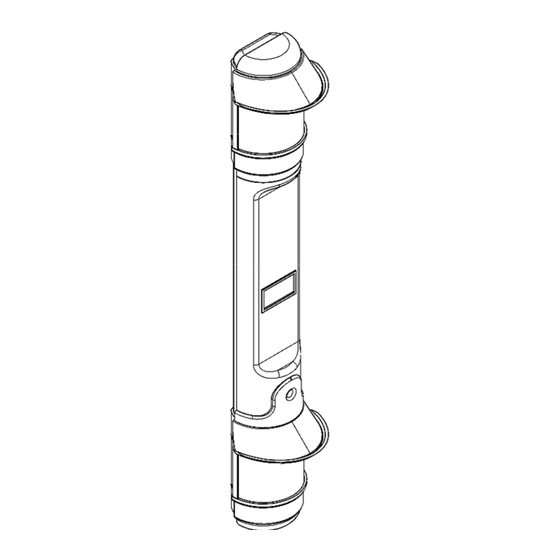
Page 11: Technical Configuration
R O B O G U A R D U S E R M A N U A L 8. Technical Configuration Fig 4: Roboguard 5 – Exploded View. The various components that make up the Roboguard. 8 8 8 8...
Need help?
Do you have a question about the Roboguard and is the answer not in the manual?
Questions and answers