
Related Manuals for SmartAVI AV Router

Summary of Contents for SmartAVI AV Router
-
Page 1: User Manual
User Manual AV Router High quality VGA RGBHV matrix that distributes signals directly. Controlled via computer. - Page 2 SmartAVI will not be liable for errors contained herein or for incidental or consequential damages in connection with the furnishing, performance or use of this material.
-
Page 3: Table Of Contents
Table of Contents Table of Contents Table of Contents Table of Contents Table of Contents Chapter 1: Introduction Chapter 1: Introduction Chapter 1: Introduction Chapter 1: Introduction Chapter 1: Introduction ........................................................................................................4 What’s in the Box ........................5 Overview ............................ -
Page 4: What's In The Box
Chapter 1: Introduction Chapter 1: Introduction Chapter 1: Introduction Chapter 1: Introduction Chapter 1: Introduction What’s in the box: t t i AVRouter Manual Version 1.0 Page 4... -
Page 5: Overview
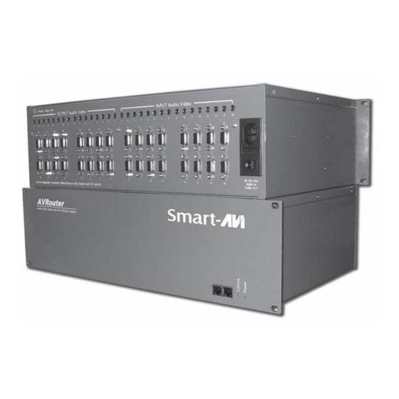
The AV Router is a high-quality switching matrix for VGA type signals. All signal formats are catered for including VGA, SVGA, XGA, RGBHV and sync on green (SOG) applications. For ease of installation, Standard VGA connectors (HD15 sockets) are used for the input as well as the output video signal. -
Page 6: Chapter 2: Installation
Chapter 2: Installation Chapter 2: Installation Chapter 2: Installation Chapter 2: Installation Chapter 2: Installation Connecting the AVRouter (Quick Start) Warning: As a precaution, we recommend that you disconnect all power cords and make sure that all devices are turned off. Plug in all external audio/video sources to the back of the AVRouter. -
Page 7: Connecting The Avrouter (Detailed Instructions)
Chapter 2: Installation Chapter 2: Installation Chapter 2: Installation Chapter 2: Installation Chapter 2: Installation Connecting the AVRouter (Detailed Instructions) Video and Audio Inputs Video and Audio Inputs Video and Audio Inputs Video and Audio Inputs Video and Audio Inputs The video input for the AVRouter is a standard HD15 connection. -
Page 8: Connecting The Communication Cable
Chapter 2: Installation Chapter 2: Installation Chapter 2: Installation Chapter 2: Installation Chapter 2: Installation Connecting the Communication Cable: RS422 Connecting the Communication Cable: RS422 Connecting the Communication Cable: RS422 Connecting the Communication Cable: RS422 Connecting the Communication Cable: RS422 Each unit can be controlled by a RS422 port connected via a RJ45 on the front of the chassis. -
Page 9: System Power On
Chapter 2: Installation Chapter 2: Installation Chapter 2: Installation Chapter 2: Installation Chapter 2: Installation AVRouter connection diagram AVRouter connection diagram AVRouter connection diagram AVRouter connection diagram AVRouter connection diagram System Power ON System Power ON System Power ON System Power ON System Power ON You are now ready to turn on the system. -
Page 10: Chapter 3: Software Installation And Operation
Chapter 3: Software Installation & Operation Chapter 3: Software Installation & Operation Chapter 3: Software Installation & Operation Chapter 3: Software Installation & Operation Chapter 3: Software Installation & Operation Find the Installation CD that came with your AVRouter unit. This CD has the SmartControl software that you will need in order to control the unit using a computer. - Page 11 Chapter 3: Software Installation & Operation Chapter 3: Software Installation & Operation Chapter 3: Software Installation & Operation Chapter 3: Software Installation & Operation Chapter 3: Software Installation & Operation Inputs/Outputs: Inputs/Outputs: Inputs/Outputs: Inputs/Outputs: Inputs/Outputs: Enter the number of Inputs/Outputs your AVRouter has. For now we will assume that there are 16 inputs and 16 outputs.
-
Page 12: The Button Panel
Chapter 3: Software Installation & Operation Chapter 3: Software Installation & Operation Chapter 3: Software Installation & Operation Chapter 3: Software Installation & Operation Chapter 3: Software Installation & Operation The Main Routing Window enables you to control the router(s) connections by means of the matrix panel, the button panel, or with pre-recorded routes called macros. -
Page 13: Macros
Chapter 3: Software Installation & Operation Chapter 3: Software Installation & Operation Chapter 3: Software Installation & Operation Chapter 3: Software Installation & Operation Chapter 3: Software Installation & Operation Macros: Macros: Macros: Macros: Macros: This section of the window is used to save and play back macros. Macros store a set sequence of routes. -
Page 14: Configuring More Than One Avrouter
Chapter 4: Additional Hardware & Operation Chapter 4: Additional Hardware & Operation Chapter 4: Additional Hardware & Operation Chapter 4: Additional Hardware & Operation Chapter 4: Additional Hardware & Operation Configuring more than one AVRouter Configuring more than one AVRouter Configuring more than one AVRouter Configuring more than one AVRouter Configuring more than one AVRouter... - Page 15 Chapter 4: Additional Hardware & Operation Chapter 4: Additional Hardware & Operation Chapter 4: Additional Hardware & Operation Chapter 4: Additional Hardware & Operation Chapter 4: Additional Hardware & Operation AVRouter Manual Version 1.0 Page 15...
-
Page 16: Chapter 5: Technical Information
Chapter 5: Technical Information Chapter 5: Technical Information Chapter 5: Technical Information Chapter 5: Technical Information Chapter 5: Technical Information AVRouter Manual Version 1.0 Page 16... -
Page 17: Chapter 6: Appendices
Chapter 6: Appendices Chapter 6: Appendices Chapter 6: Appendices Although the following communication protocol has been specifically written for the SmartNet-X unit from SmartAVI, it is accurate for the AVRouter and other units from SmartAVI. 1.0 Document Conventions Any numbers preceded by ‘0x’ are hexadecimal. - Page 18 Chapter 6: Communication Protocol Chapter 6: Communication Protocol Chapter 6: Communication Protocol Chapter 6: Communication Protocol Chapter 6: Communication Protocol This is achieved by creating a loop between chassis using the comms IN and OUT ports on the front of the chassis. i.e.
- Page 19 Chapter 6: Communication Protocol Chapter 6: Communication Protocol Chapter 6: Communication Protocol Chapter 6: Communication Protocol Chapter 6: Communication Protocol Where; < S o u r c e > < S o u r c e > < S o u r c e > =Single Byte, Switch Input channel -1 <...
- Page 20 Chapter 6: Communication Protocol Chapter 6: Communication Protocol Chapter 6: Communication Protocol Chapter 6: Communication Protocol Chapter 6: Communication Protocol Set Audio Only Crosspoint Set Audio Only Crosspoint Set Audio Only Crosspoint Set Audio Only Crosspoint Set Audio Only Crosspoint Cmd = 4 Databytes = destination, source i.e.
- Page 21 Chapter 6: Communication Protocol Chapter 6: Communication Protocol Chapter 6: Communication Protocol Chapter 6: Communication Protocol Chapter 6: Communication Protocol The command to make the end of CAT5 line receiver (SLRX-RX300) switch between its local and remote sources is as follows; <0xBE><0xEF><Frame Address><Reserved><CMD><DATA BYTES><BCC>...
- Page 22 Chapter 6: Communication Protocol Chapter 6: Communication Protocol Chapter 6: Communication Protocol Chapter 6: Communication Protocol Chapter 6: Communication Protocol Comms Cable Comms Cable Comms Cable Comms Cable Comms Cable 1 1 1 1 1 - - - - - - - - - - 2 2 2 2 2 3 3 3 3 3...
- Page 23 Chapter 6: Communication Protocol Chapter 6: Communication Protocol Chapter 6: Communication Protocol Chapter 6: Communication Protocol Chapter 6: Communication Protocol Appendix B: Continued….. Appendix B: Continued….. Appendix B: Continued….. (Sample Translation routine in Visual BASIC) (Sample Translation routine in Visual BASIC) (Sample Translation routine in Visual BASIC) Appendix B: Continued…..
- Page 24 Customer is responsible for maintaining proof of date of purchase. 2. SmartAVI limited warranty covers only those defects which arise as a result of normal use of the product, and do not apply to any: a.
- Page 25 Chapter 6: Appendices Chapter 6: Appendices Chapter 6: Appendices Chapter 6: Appendices Chapter 6: Appendices AVRouter Manual Version 1.0 Page 25...
- Page 26 SmartAVI, Inc. SmartAVI, Inc. SmartAVI, Inc. SmartAVI, Inc. SmartAVI, Inc. 3111 Winona Ave, Suite 101 Burbank, CA 91504 Tel (818) 565-0011 Fax (818) 565-0020 Email: info@smartavi.com...
Need help?
Do you have a question about the AV Router and is the answer not in the manual?
Questions and answers