Table of Contents
Advertisement
Quick Links
Advertisement
Table of Contents

Summary of Contents for ZES ZIMMER LMG450
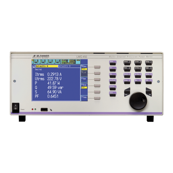
- Page 1 4 Channel LMG450 Power Meter User manual Status: 2009/02/17...
- Page 3 Internet: http://www.zes.com No part of this document may be reproduced, in any form or by any means, without the permission in writing from ZES ZIMMER Electronic Systems GmbH. Regard DIN 34! We reserve the right to implement technical changes at any time, particularly where these...
- Page 7 Test Certification Instrument Type: Serial Number: ZES ZIMMER Electronic Systems GmbH certifies the above instrument to comply with all specifications contained in the delivered user manual. It has left the factory in mechanically and electrically safe condition. The measuring instruments, tools and standards used in production, adjustment and calibration are calibrated according to ISO9000 (traceable to national standards) and correspond to the standard of precision required to maintain the specified accuracies.
- Page 9 Request/order for a calibration Instrument: LMG90 LMG95 LMG310 LMG450 LMG500 other: Serial number: For the above instrument the following should be done: Calibration Adjustment with following Input calibration, adjustment and (order-no KR-xxx) calibration (order-no JKR-xxx) output calibration (order-no KJKR-xxx) I don’t want to get the latest software in the instrument (free of charge). I want to keep the actual implemented software version.
-
Page 11: Table Of Contents
3.1 Unpacking and putting into operation............37 3.2 General set-up..................37 3.3 Connections of the LMG450..............37 3.3.1 Measuring circuit for typical line applications using the internal current path ..38 3.3.2 Measuring circuit for measuring efficiency of 3/1phase systems......39 3.3.3 Measuring circuit (typical) for star to delta conversion (option L45-O6) ..... - Page 12 5.2 Measuring ranges (Range) ..............81 5.2.1 Group A/B tab....................81 5.2.2 Sense/More tab....................82 5.3 Definition of measuring values ..............83 5.3.1 Values from single measuring................87 5.3.2 Integrated values....................89 5.3.3 Total values ......................90 5.4 Display of values ..................91 5.4.1 Default .......................
- Page 13 7.4.7 Custom menu....................117 7.5 Storage of values .................. 117 7.6 Tests according EN61000-3-3............... 117 8 100 Harmonics measuring mode (option L45-O8) .......119 8.1 Measuring configuration (Measuring)............ 119 8.2 Measuring ranges (Range) ..............120 8.3 Definition of measuring values .............. 120 8.4 Display of values ..................
- Page 14 10.2.19 SCPI command Example................223 10.2.20 SHORT command Example ................225 10.3 Physical devices.................. 228 10.3.1 The serial interfaces ..................228 10.3.2 IEEE488.2...................... 229 10.3.3 Parallel Port....................229 11 Logging of values to drives, printer and interfaces .....231 11.1 Start of logging ................... 231 11.2 End of logging ..................
- Page 15 14.1 Further connectors ................265 14.1.1 External Synchronisation (Sync.) ..............265 14.1.2 External Current Sensor.................. 269 14.2 Functional block diagram LMG450............. 270 14.3 Functional block diagram voltage channels.......... 271 14.4 Functional block diagram current channels.......... 272 14.5 Functional block diagram computing unit ..........273 14.6 Functional block diagram processing signal interface ......
- Page 16 Figure 39 Measuring menu in transient mode ..............126 Figure 40: Keynumbers....................... 214 Figure 41: COM A connector ..................... 228 Figure 42: COM B connector ..................... 229 Figure 43: Dimensions of LMG450..................254 Figure 44: Processing Signal Interface Connector ............... 262 Figure 45: Sync. connector ....................265...
- Page 17 Figure 46: External current sensor connector ..............269 Figure 47: Functional block diagram LMG450..............270 Figure 48: Functional block diagram voltage channels............271 Figure 49: Functional block diagram current channels ............272 Figure 50: Functional block diagram computing unit ............273...
-
Page 19: Instructions And Warnings
Z E S ZIMMER Electronic Systems GmbH Chapter 1 Instructions and Warnings Safety Instructions This instrument conforms to the IEC61010-1 guide lines concerning the protection of electrical instrumentation and has left the factory in a mechanically and electrically safe condition. To maintain safe operation, the user must follow the instructions and warnings contained in this manual. - Page 20 Instructions and Warnings LMG450 repair work must then be carried out by a suitably qualified person who is familiar with any dangers involved. It must be considered unsafe to operate the instrument: • if there is visual evidence of physical damage •...
- Page 21 Z E S ZIMMER Electronic Systems GmbH Chapter 1 Attention! The following maximum values must not be exceeded: I*, I: maximum 18A (short-time 50A), maximum 600V@CATIII operating voltage against earth, instrument casing and voltage channel. Sensor Input: maximum 8V signal voltage. U*,U: maximum 600V (short-time 1500V) between U and U*, maximum 600V@CATIII operating voltage against earth,...
-
Page 23: General
Features and application areas Voltages and currents can be measured over a wide dynamic range. This makes the LMG450 instrument suitable for almost all professional measurement applications such as converter-fed alternating current machines and power- and energy electronic applications. Various wire- and phase configurations can be pre-selected to suit any required user application. -
Page 24: Usage Of The Manual
There are following measuring modes: • normal mode In this mode the LMG450 works as a power-meter with integrated scope function. The... -
Page 25: General Handling Of The Instrument
This mode can only be used for precompliance measurings. • CE flicker mode In this mode the LMG450 works as a full compliance flicker meter. All measurements are judged according to the standards. There is only a minimum of settings to prevent set-up errors. - Page 26 General LMG450 By rotating the knob, you can select different tabs. By pushing the knob, you get a new selection of softkeys in a lower menu layer. By rotating the knob, you can select different actions (depends on the context of the menu).
-
Page 27: The Group Concept
Z E S ZIMMER Electronic Systems GmbH Chapter 2 Count softkey. After pressing this softkey you can adjust the depending values with the opening up and down buttons in fixed steps. Time softkey. After pressing this softkey you can adjust a time setting. The values for hours, minutes and seconds must be separated by a colon, pressing the button Misc. - Page 28 General LMG450 frequency converters or standard main supply with L1, L2, L3, N and PE (in this case you could for example measure I and U In this situation there is no group B! The standard wiring for this is ‘4+0 Channels’.
- Page 29 Z E S ZIMMER Electronic Systems GmbH Chapter 2 Following you find an overview over the different wirings, the groups, the measured values and where you can find the values in the display. The definition of the header can be found in chapter 5.4, ‘Display of values’.
- Page 30 General LMG450 Display Group Meaning Header with Aron channel set to off The values measured with the fourth measuring Chn4 B:4 channel The calculated (not measured) current I and voltage Link12 (U3,I3) A:5 of group A (linked channel) The calculated (not measured) current I...
-
Page 31: Linked Values, Star To Delta Conversion (Option L45-O6)
Z E S ZIMMER Electronic Systems GmbH Chapter 2 All measuring channels All channels calculated from sample values (linked channels) All channels calculating the total values of a group (sum channels) Linked values, star to delta conversion (option L45-O6) If you have installed the option star to delta conversion you can calculate values, which you can’t measure directly (for example if you have a load in delta circuit, and want to know, how big is the power in each load, you could use the wiring ‘3+1, U∆I*->U∆I∆’. - Page 32 General LMG450 Following you find an overview over the different wirings, the groups, the measured values and where you can find the values in the display. After the grouping of the wiring you see how the signals are connected to instrument and what values are calculated.
- Page 33 Z E S ZIMMER Electronic Systems GmbH Chapter 2 Display Group Meaning Header channel The values in delta circuit, calculated from Link123 (U23,I23) A:6 display channel 1 to 3 (U The values in delta circuit, calculated from Link123 (U31,I31) A:7 display channel 1 to 3 (U The total values (sum channel) of group A Sum(5-7) A:13...
- Page 34 General LMG450 Display Group Meaning Header channel The values measured with the third measuring Chn3 (U12,I1) B:3 channel (U ’, I ’) The values measured with the fourth measuring Chn4 (U32,I3) B:4 channel (U ’, I ’) The calculated (not measured) current I...
- Page 35 Z E S ZIMMER Electronic Systems GmbH Chapter 2 Display Group Meaning Header channel The calculated (not measured) current I Link12 (U31,I2) A:5 voltage U of group A (linked channel) The calculated (not measured) current I ’ and Link34 (U31,I2) B:6 voltage U ’...
-
Page 37: Installation
The package should be stored for further transports (e.g. for the annual calibration according to ISO9000). After delivery the following items should be present: • LMG450 4 channel measuring instrument • User manual • Safety laboratory leads, 2.5mm², 1m, 8 in violet, 8 in grey •... -
Page 38: Measuring Circuit For Typical Line Applications Using The Internal Current Path
Installation LMG450 The following diagrams are some examples for typical connections of the LMG450. But all other measuring circuits are also possible (e.g. circuits which measure the correct current instead of the correct voltage). 3.3.1 Measuring circuit for typical line applications using the internal current... -
Page 39: Measuring Circuit For Measuring Efficiency Of 3/1Phase Systems
Z E S ZIMMER Electronic Systems GmbH Chapter 3 3.3.2 Measuring circuit for measuring efficiency of 3/1phase systems G roup A G roup B L’ N ’ Figure 4: Measuring circuit for measuring efficiency (3/1phase) With group A you measure the three phase power, with group B the one phase power of the system. -
Page 40: Measuring Circuit (Typical) For Star To Delta Conversion (Option L45-O6)
Figure 5: Star to delta conversion With group A you measure the linked voltages and the currents in the phases. The LMG450 calculates with this both values a power for each channel, but this power will not be the power... -
Page 41: Aron Wiring
Z E S ZIMMER Electronic Systems GmbH Chapter 3 3.3.4 Aron wiring C T 1 V T 1 C T 2 V T 2 Figure 6: Measuring circuit with current and voltage transformers in Aron wiring This wiring is for measuring the power of a three phase system without a neutral conductor. This circuit should be measured with wiring ‘2+2 Channels’. -
Page 42: Measuring Circuit For Measuring Efficiency Of 3/3Phase Systems
Installation LMG450 3.3.5 Measuring circuit for measuring efficiency of 3/3phase systems G ro up A G ro up B L1’ L2’ L3’ Figure 7: Measuring circuit for measuring efficiency (3/3phase) With group A you measure the first three phase power, with group B the second one. The frequencies of group A and B can be different. -
Page 43: Measurement Of High Currents
Figure 9: Measuring circuit for measuring high currents with transformers, voltage directly In this figure you see how to measure a 3/4 phase system with high currents. The current path is connected via transformers to enlarge the ranges of the LMG450. For this measurement you should use the wiring ‘3+1 Channels’. -
Page 44: Measurements At Middle And High Voltage Systems
Installation LMG450 3.3.8 Measurements at middle and high voltage systems C T 1 V T1 C T 2 V T2 C T 3 V T3 Figure 10: Measuring circuit for measuring in middle and high voltage systems This is the measuring circuit for measuring in middle and high voltage systems. You can see that there is no PE conductor. -
Page 45: Measurements At Middle And High Voltage Systems Without N
Z E S ZIMMER Electronic Systems GmbH Chapter 3 3.3.9 Measurements at middle and high voltage systems without N C T 1 V T1 C T 2 V T2 A rtificial m idpoint Figure 11: Measuring circuit for measuring in middle and high voltage sytems without N Using artificial midpoint This is the measuring circuit for measuring in middle and high voltage systems without the neutral N. -
Page 46: Measurements At Middle And High Voltage Systems Without N
Installation LMG450 3.3.10 Measurements at middle and high voltage systems without N C T 1 V T1 C T 2 V T2 Figure 12: Measuring circuit for measuring in middle and high voltage sytems without N Using star to delta conversion This is the measuring circuit for measuring in middle and high voltage systems without the neutral N. -
Page 47: Instrument Controls
2. Softkeys Their function depends on the indicated function in the display. 3. Special function keys Status: Here you get status information about the LMG450 Start: This key is used to start time dependent measurements Stop: This key is used to stop time dependent measurements... -
Page 48: Rear Panel
Instrument controls LMG450 5. Violet menu selection keys With this keys you can call several menus for setting up the instrument: Measure: The main measuring parameters Int. Time: The parameters for time dependent measuring Custom: The set-up of the custom defined menus... - Page 49 Additional analogue and digital inputs and outputs for auxiliary signals. 13. IEEE488 Parallel interface, 24-pin micro-ribbon socket 14. Sync. Socket for external synchronisation and measuring time control of the LMG450. 15-pin SUB-D socket 15. ComB: Serial RS232 interface This is a serial interface which is reserved for further usage...
-
Page 50: Display
Instrument controls LMG450 16. ComA: Serial RS232 interface This is the standard serial interface for remote control of the LMG450. This interface is also used for software updates and service purposes. 9-pin SUB-D socket 17. Channel extension Here you can later on connect additional measuring channels. -
Page 51: General Menues
Z E S ZIMMER Electronic Systems GmbH Chapter 4 Li for line synchronisation Ex for external synchronisation As (inverse) for asynchronous (no synchronisation) The lower information can be: ‘LF’ (inverse displayed ) indicating that the signal of the channel is low pass filtered. The implemented ‘A’... -
Page 52: Figure 16: Misc. Menu
For the exact adjustment steps please refer to 12.3.2 ‘Adjustment The adjustment has to be done at (23±1)°C. ZES ZIMMER offers in principle a way to adjust the instruments outside our factory, if some technical preconditions are fulfilled. For further information, please contact sales@zes.com... -
Page 53: If/Io
Z E S ZIMMER Electronic Systems GmbH Chapter 4 4.4.2 IF/IO In this menu you can set-up all features which are available as instrument options. Further on you see the actual software version and the installed options. With List you can choose a short list or detail list. - Page 54 Possible values are ‘<lf>‘, ‘<cr>, <cr><lf>‘ and ‘Terminal’. In ‘Terminal’ mode each ‘<cr>‘ of the computer is answered by a ‘<cr><lf>‘ of the LMG450. By this you get a nice display if you use an terminal program (if you have also activated the echo).
- Page 55 Back returns to the IF/IO menu. In the LMG450 you can install one ore two processing signal interface cards. So the number of channels which are displayed in each menu depends on the number of installed cards.
-
Page 56: Figure 18: Analogue Inputs
Instrument controls LMG450 Figure 18: Analogue inputs Pressing the rotary knob returns you to the tab selection. 4.4.2.2.2 Analogue Output tab If you are in the setting mode of this menu, you can with the rotary knob select a channel. -
Page 57: Figure 20: Digital Inputs
Z E S ZIMMER Electronic Systems GmbH Chapter 4 Pressing the rotary knob returns you to the tab selection. 4.4.2.2.3 Digital Inputs tab In this menu you get the actual state of the digital inputs. The inputs 1 to 4 of each card are only used for state indication. -
Page 58: Figure 21: Limit Menu
Instrument controls LMG450 Example: You select ‘Utrms:1 < 200V’. Now you get an alarm for every voltage smaller than 200V. The output becomes a high impedance state because a ‘fail save’ function is assumed. Figure 21: Limit menu Pressing the rotary knob returns you to the tab selection. -
Page 59: Custom Menu
Z E S ZIMMER Electronic Systems GmbH Chapter 4 4.4.3 Custom menu In the standard menus Voltage, Current, ... (see chapters below) we have defined some values to be displayed which should fit to most customers. For some special applications you can define in the Custom menu your own values and graphics which should be displayed. -
Page 60: Script/Formula Editor
Instrument controls LMG450 String When choosing this have to choose with Prop a text which should be displayed. How to enter the Prop value see 4.5, ‘Entering identifiers, characters and text’. Graph Here you get a list of all possible graphs. In principle you can display copies of graphs which you have already set-up in the Graph menu. - Page 61 Z E S ZIMMER Electronic Systems GmbH Chapter 4 With Load you can recall a previously saved script. 4.4.4.1 General The script editor is similar like a simple programming language. The code is entered line by line. It is allowed to have several instructions in one line. Each instruction has to end with a ‘...
- Page 62 Instrument controls LMG450 An instruction consists of one or more expressions. Each instruction (except else has to be finished with ‘ ’. An instruction can be longer than one line. The result must not be assigned to a variable. 4.4.4.2.2 Condition instruction Condition instructions choose between two alternative program flows.
- Page 63 There is a distinction between read only variables and read write variables. The first ones are all measuring values of LMG450 but also values like cycle time and measuring ranges. This variables can be used for calculation like constants. The second one are the user defined variables.
- Page 64 Instrument controls LMG450 4.4.4.2.6 Keywords These are strings which are no variables or constants but which are used for controlling the script editor: The start of a conditioned program sequence. The condition have to follow in the round brackets. The end of the program sequence which is used if the condition of the...
- Page 65 Z E S ZIMMER Electronic Systems GmbH Chapter 4 dout_on(nr) Switches digital output number nr on (into alarm state). 1≤nr≤4(8) freeze() freezes the display (like key Freeze) isrun() Returns 1, if the integration is running isstop() Returns 1, if the integration is stopped ln(x) of x log(x)
- Page 66 Instrument controls LMG450 Negation Exponent Division and Multiplication Addition and Subtraction smaller, equal, bigger (comparator operators) <, ==, > Assignment of a value not equal <> low priority If there are no brackets, the operators are used in the order listed above.
- Page 67 Z E S ZIMMER Electronic Systems GmbH Chapter 4 if (Uhigh==0) Ulow=RngU:1; if (Uhigh<Utrms:1) Uhigh=Utrms:1; if (Ulow>Utrms:1) Ulow=Utrms:1; The first condition is used for resetting the minimum value: With Reset it would be set to 0 which is not sufficient, because this is already the smallest TRMS value. So if the maximum TRMS value is reset to 0.0, the minimum value is set to the range value which will not be reached under proper conditions.
- Page 68 Instrument controls LMG450 4.4.4.2.15 Example 6: Calculation of the efficiency of a motor with torque and frequency input For the measurement of the efficiency of a motor you can use the analogue and the frequency inputs. To input the torque of the motor use the analogue input (e.g. 1) and for the frequency use the digital frequency input (e.g.
- Page 69 Z E S ZIMMER Electronic Systems GmbH Chapter 4 The two functions are: torque(Pn,fn,Un,In,pfn,pz,Rk,13,mk) Calculates the torque in Nm. The parameters are: Pn: Nominal output power in W Nominal frequency in Hz Un: Nominal line line voltage of the motor in V Nominal current in A pfn: Nominal power factor...
-
Page 70: Saving And Restoring Configurations
Instrument controls LMG450 $jn=4.66; # Nominal current in A $un=400; # Nominal L-L voltage in V $pn=2200; # Nominal output power in W $fn=50; # Nominal frequency in Hz $rk=19.7; # resistor in Ohm # terminal to terminal # (hot resistor) $mk=20;... - Page 71 Z E S ZIMMER Electronic Systems GmbH Chapter 4 Enter or the rotary knob. In this case you have to enter the letters in the same way you see them in the menus (e.g. ‘Utrms’). Or you can press the key of any valid menu (e.g. Voltage, Current, ...) and you get a list of the available values (in this mode).
- Page 72 Instrument controls LMG450 Default Current Voltage Power Int. Value Measure Custom Misc. IF/IO RngU Uscal var0-11 Xser prCE Harmonic measuring mode Default Current Voltage Power Measure Custom Misc. IF/IO abs() Mtime var0-11 acos() DigFrq Imav Imav Uthd asin() Zero bell()
- Page 73 Z E S ZIMMER Electronic Systems GmbH Chapter 4 Default Current Voltage Power Measure Custom Misc. IF/IO Xser CE Flicker measuring mode Default Current Voltage Power Int. Value Measure Custom Misc. IF/IO Uhwcf Uhwcf Uhwcf abs() Mtime var0-11 acos() DigFrq dmaxl FlkPer asin()
- Page 74 Instrument controls LMG450 HARM100 measuring mode Default Current Voltage Power Measure Custom Misc. IF/IO abs() Mtime var0-11 acos() DigFrq Ithd Uthd asin() Zero Ithd bell() Itrms Utrms cos() RngI RngU digin() Iscal Uscal dout_on() OvrI OvrU dout_off() Rser freeze() Uthd...
-
Page 75: Entering Numerical Values
Z E S ZIMMER Electronic Systems GmbH Chapter 4 To select another position in the text, you have to set Mode to ‘move’ or ‘line’. With ‘move’ you move character by character, with ‘line’ you move line by line, which is much faster in bigger text. -
Page 77: Normal Measuring Mode
Z E S ZIMMER Electronic Systems GmbH Chapter 5 Normal measuring mode In the normal measuring mode the LMG450 works as a four channel power meter. The voltage, current and power are measured directly, many other values are derived from these values. -
Page 78: Group A/B Tab
Normal measuring mode LMG450 to see the real phase shift between the phases. The voltage measured with the third channel is also inverted. 5.1.2 Group A/B tab The settings in group A and B are identical, so they are just described once. Each setting... - Page 79 Z E S ZIMMER Electronic Systems GmbH Chapter 5 Signl Here you define the signal you want to trigger on. Available are: u, i, p, u², i², . For the meaning of this values please watch the functional filt filt filt diagram in 14.5, ‘Functional block diagram computing unit’...
- Page 80 Normal measuring mode LMG450 Setting Meaning All filters are switched off HF-Rej The analogue HF rejection filter is switched on. Especially when using frequency converters this HF rejection filter should be switched on. 30Hz Additionally to the HF rejection filter a digital Low-Pass Filter with a cut off...
-
Page 81: Measuring Ranges (Range)
Z E S ZIMMER Electronic Systems GmbH Chapter 5 Figure 23: Measuring menu in normal mode Measuring ranges (Range) When you came to this menu by pressing Range you can setup all the ranges and scalings for the different measuring channels. You see three tabs (‘Group A’, ‘Group B’ and ‘Sense/More’). -
Page 82: Sense/More Tab
Normal measuring mode LMG450 factor. Example 2: You have a current clamp with 1A/10mV ratio. This is equal to 100A/V, so you have to enter 100 as scaling. Here you define the action of the rotary knob. You can change between the different channels (‘Chn’) or you can change the range in the selected channel... -
Page 83: Definition Of Measuring Values
Z E S ZIMMER Electronic Systems GmbH Chapter 5 Definition of measuring values Following you find the definitions for all measuring values in the normal operation mode. The values are divided in two sections: • The values from single measuring are measured while one measuring cycle and are independent from all other measuring cycles. -
Page 84: Figure 25: Allocation Of The Different Linked Values
Normal measuring mode LMG450 Display channel u(t) i(t) (t)+u (t)-i (t)+u (t)-i For further information about the tables see also chapter 2.4, ‘The group concept’. Linked values If you have installed the option L45-O6 (star to delta conversion) you get the following additional wirings. - Page 85 Z E S ZIMMER Electronic Systems GmbH Chapter 5 Wiring ‘3+1, U*I*-> U∆I∆’ Measuring channel Circuit numbers numbers Display channel u(t) i(t) − (t)-u i (t) i (t) − (t)-u i (t) i (t) − (t)-u i (t) i (t) For circuit see 3.3.2, ‘Measuring circuit for measuring efficiency of 3/1phase systems’...
- Page 86 Normal measuring mode LMG450 Measuring channel Circuit numbers numbers Display channel u(t) i(t) − u (t) u (t) − u (t) u (t) − u (t) u (t) For circuit see 3.3.3, ‘Measuring circuit (typical) for star to delta conversion (option L45-O6)’...
-
Page 87: Values From Single Measuring
Z E S ZIMMER Electronic Systems GmbH Chapter 5 Wiring ‘2+2, U∆I*-> U*I*’ Measuring channel numbers Circuit numbers Display channel u(t) i(t) U13’ I1’ U23’ I2’ (t)+u (t)-i (t) U12 (t)+u (t)-i (t) U12’ I3’ − 2u (t) u (t) −... - Page 88 Normal measuring mode LMG450 − − AC component: Utrms Itrms − − peak-peak value: max( ( )) min( ( )) max( ( )) min( ( )) ∫ ∫ rectified value: Urect u t dt Irect i t dt crest factor:...
-
Page 89: Integrated Values
Z E S ZIMMER Electronic Systems GmbH Chapter 5 Impedances Utrms apparent impedance: Itrms active impedance: Rser Itrms reactive impedance Xser Itrms 5.3.2 Integrated values The following basic definitions are used: The value from the measuring cycle number n. Is the number of measuring cycles for the integration. This number depends on the real measuring times and on the desired integration time. -
Page 90: Total Values
Normal measuring mode LMG450 5.3.3 Total values This are values which are calculated over several channels of one group. Following symbols are used: first channel of the group last channel of the group number of the display channel for the total values These three symbols depend on the wiring. -
Page 91: Display Of Values
Z E S ZIMMER Electronic Systems GmbH Chapter 5 average reactive power: ∑ average apparent power: ∑ All this calculation are in accordance with DIN40110. Display of values For the display of the values you can choose several menus. Also in this menus we have the group concept. -
Page 92: Default
Normal measuring mode LMG450 The following examples exit if you have the wiring ‘A:1+2 B:3+4’ and the Aron field is switched on in the measuring menu. Example: Chn2 (U23,I2) A:2 This is the measuring channel 2. It should be connected to U23 and I2 of your circuit. It belongs to group A and has the display channel number 2. -
Page 93: Voltage
Z E S ZIMMER Electronic Systems GmbH Chapter 5 Figure 26: Default display with one and four channels 5.4.2 Voltage With Voltage you see the most important voltage values of the instrument. For the handling please see the general description in chapter 5.4, ‘Display of values’. 5.4.3 Current With Current you see the most important current values of the instrument. -
Page 94: Energy
Normal measuring mode LMG450 following resistor values: Z, X and R. Please note that the values of X and R are only correct, if the voltage and current have a sinusoidal waveform! 5.4.5 Energy In this menu (you reach it by Int. Val) you see the most important energy values as well as derived values which also depend on time. -
Page 95: Graphical Display
Start Time, Start Date, or you can simply press the Start button or you can start via the external sync jack of the LMG450 (see 14.1.1). The first cycle which is taken into account is the cycle which follows the actual cycle. - Page 96 Normal measuring mode LMG450 scaling factor (xzoom) and the X scaling (x/div). By pressing the rotary knob you can do the following settings: Graph Here you can select one of the four scope channels ‘A’ to ‘D’. Signal Here you can choose the signal to be displayed. The possible values depend on the chosen wiring.
-
Page 97: Figure 27: Scope Display With Split Off/On
Z E S ZIMMER Electronic Systems GmbH Chapter 5 Figure 27: Scope display with split off/on 5.4.6.2 Plot function Figure 28: The plot display; split off In this menu all measured values can be displayed over the time in one or four plots. On the left side, the information segment, the following settings are displayed: The plotted signal is shown in the colour in which the graph is drawn. - Page 98 Normal measuring mode LMG450 scaling of the y axis per division offset of the y axis (value of the centre line) value of the function at the cursor position Below the graphs the time depending values are displayed: scaling of the x axis per division...
-
Page 99: Figure 29: The Plot Display; Split On
Z E S ZIMMER Electronic Systems GmbH Chapter 5 same as c1 c1&c2 both cursors are moved at the same time. Split after pressing this button the display will be split in four separated graphs, refer the following picture: Figure 29: The plot display; split on Hint: the settings of the cursor are the same for all four to get accurate readings at the selected moment for all channels. -
Page 100: Figure 30: Vector (Fresnel) Diagramm
Normal measuring mode LMG450 Figure 30: Vector (Fresnel) diagramm Please note following 1. The angels between the voltages are calculated from the time of the zero crossing in each phase. If you have big distortions on the voltage, this values might be wrong. You can use all possible filter to smooth the voltage. -
Page 101: Custom Menu
Z E S ZIMMER Electronic Systems GmbH Chapter 5 • Cycls allows you to define the minimum duration in times of the cycle time. • Because of this many influence factors the storing rate and the real duration (both displayed) will vary if you change any of this parameters. In general you can say: •... -
Page 103: Prce-Harmonic Measuring Mode
Z E S ZIMMER Electronic Systems GmbH Chapter 6 prCE-Harmonic measuring mode In the prCE-Harmonic measuring mode the LMG450 works as an high precision harmonic analyser. The number of settings have been reduced to the needed ones to avoid fail handling. Note! The synchronisation is fixed to U. -
Page 104: Group A/B Tab
LMG450 2:95/-4-7:93 The combination EN61000-3-2:1995 and EN61000-4-7:1993 is active 2:95/-4-7:08 The combination EN61000-3-2:1995 and EN61000-4-7:2002 is active 2:06/-4-7:93 The combination EN61000-3-2:2000 and EN61000-4-7:1993 is active 2:06/-4-7:08 The combination EN61000-3-2:2000 and EN61000-4-7:2002 is active 12:05/-4-7:08 The combination EN61000-3-12:2005 and EN61000-4-7:2002 is active Systm This selects the system which is used for the measurement. -
Page 105: Measuring Ranges (Range)
Z E S ZIMMER Electronic Systems GmbH Chapter 6 This tab is only accessible if you have chosen EN61000-3-2:2006 with Class C or D or EN61000-3-12:2005! Here you have to setup the setting which are required for EN61000-3-2:2006. For class C you have to enter the fundamental current and the power factor or your device. -
Page 106: Display Of Values
LMG450 ∫ ∫ DC component: u t dt i t dt − − AC component: Utrms Itrms crest factor: Utrms Itrms ∑ ∑ total harmonic distortion: Uthd Ithd ... -
Page 107: Default
Z E S ZIMMER Electronic Systems GmbH Chapter 6 6.4.1 Default With Default you see the most important values of the instrument. For the handling please see the general description in chapter 5.4, ‘Display of values’. 6.4.2 Voltage With Voltage you see the harmonic values of the measured voltage and in the second row the allowed limits in this voltage (if you see a single channel). -
Page 108: Power
LMG450 If the current is <5mA or <0.6% of I there is no judgement of the current. For this reason trms ‘------’ is displayed for the limit. With the arrow keys or with the shuttle knob you can scroll through the list to see all harmonics. -
Page 109: Graphical Display
Z E S ZIMMER Electronic Systems GmbH Chapter 6 Figure 33: Long time evaluation of harmonics Below the softkeys you see the total evaluation of the measurement. If any current harmonic has violated the standard at any time or the differences between control and measured values of power (class D) or of current and power factor (class C) were more then 10% (only for &... -
Page 110: Figure 34: Graphical Display Of Harmonics
LMG450 For the displays with limits and harmonics you have always one thin bar with the limit, one thin bar with the measuring value and again one thin bar with the limit. So the value is covered by the limits. -
Page 111: Custom Menu
Z E S ZIMMER Electronic Systems GmbH Chapter 6 6.4.7 Custom menu With Custom you see the custom menu. Here you can setup your own menus, calculate formulas and execute programs. See 4.4.3, ‘Custom menu’ and 4.4.4, ‘Script/Formula editor’. Storage of values First you have to change to the menu you want to print out or to store and press Print/Log (exact handling see 11, ‘Logging of values to drives, printer and interfaces’). -
Page 113: Ce-Flicker Measuring Mode (Option L45-O4)
Z E S ZIMMER Electronic Systems GmbH Chapter 7 CE-Flicker measuring mode (option L45-O4) In the CE-Flicker measuring mode the LMG450 works as an high precision flicker analyser according to IEC61000-4-15. The number of settings has been reduced to the needed ones to avoid fail handling. -
Page 114: Ztest/Zref Tab
CE-Flicker measuring mode (option L45-O4) LMG450 Per. This is the number of short term periods for the long term measurement. The standard value is 12 periods for a long term time of 2 hours. Figure 35: Measuring menu in CE-Flicker mode 7.1.2... -
Page 115: Display Of Values
Z E S ZIMMER Electronic Systems GmbH Chapter 7 Voltage and current ∫ ∫ true root mean square: Utrms u t dt Itrms i t dt ∑ ∑ total harmonic distortion: Uthd Ithd ... -
Page 116: Voltage
CE-Flicker measuring mode (option L45-O4) LMG450 7.4.2 Voltage Here you see the TRMS value, the THD and the frequency. 7.4.3 Current Here you see the TRMS value, the THD and the frequency. 7.4.4 Power For the display of the values we have the same rules like in the normal measuring mode (see 5.4, ‘Display of values’) -
Page 117: Graphical Display
Z E S ZIMMER Electronic Systems GmbH Chapter 7 is calculated at the end of the long term measuring. Until then it is displayed as ‘-------’. 7.4.6 Graphical display Here just the plot function is available. The handling is the same like described in 5.4.6, ‘Graphical display’... -
Page 119: 100 Harmonics Measuring Mode (Option L45-O8)
Chapter 8 100 Harmonics measuring mode (option L45-O8) In the 100 Harmonics measuring mode the LMG450 works as a high precision harmonic analyser. The difference to the prCE mode is, that 100 harmonics, the phase angles and the power harmonics are measured. The frequency range is much wider. There is no check against any limits. -
Page 120: Measuring Ranges (Range)
100 Harmonics measuring mode (option L45-O8) LMG450 Measuring ranges (Range) The settings are the same like in 5.2 ‘Measuring ranges (Range)’, but in this mode you have no autorange function. Definition of measuring values The following basic definitions are used: The harmonic order. -
Page 121: Display Of Values
Z E S ZIMMER Electronic Systems GmbH Chapter 8 The harmonic values ‘I(n)’, ‘U(n)’ and ‘Phase(n)’ are calculated by using a DFT algorithm. With this values also the values of ‘P(n)’, ‘S(n)’ and ‘Q(n)’ are calculated. This ‘Q(n)’ is only the reactive power, caused by a phase shift of a voltage and current component with the same frequency. -
Page 122: Default
100 Harmonics measuring mode (option L45-O8) LMG450 the filters for this values! For the same reason this values can also be much bigger than the values which can be derived from the harmonics (depending on the signal). 8.4.1 Default With Default you see the most important values of the instrument. The available settings are described in „5.4 Display of values“. -
Page 123: Graphical Display
Z E S ZIMMER Electronic Systems GmbH Chapter 8 With List you can choose several lists with the different combinations of the different powers. Using the rotary knob you can scroll through the list to see all harmonics. 8.4.5 Graphical display Here just the plot function, the spectrum and the vector diagram is available. -
Page 125: Transient Mode (Option L45-O5)
Z E S ZIMMER Electronic Systems GmbH Chapter 9 Transient mode (option L45-O5) In the transient measuring mode the LMG450 works as a transient recorder. You can define special events. If they occur the measuring is stopped and you can analyse the signal. Measuring configuration (Measuring) When you came to this menu by pressing Measure you first have to choose MODE and then TRANS to enter this mode. -
Page 126: Figure 39 Measuring Menu In Transient Mode
Transient mode (option L45-O5) LMG450 General • The settings of a group are valid for all channels of the group. • The channels of a group are OR combined. If at least one channel is triggered, the complete group is triggered. - Page 127 Z E S ZIMMER Electronic Systems GmbH Chapter 9 Limit Here you can setup the limits for the events. The instantaneous value of the signal to be watched is checked against the limit if it is bigger (or smaller) an event is generated.
-
Page 128: Measuring Ranges (Range)
Transient mode (option L45-O5) LMG450 If you enter the transient mode the instrument is always in the ‘Idle’ state (see status line). To start a transient search press Start. In the status line changes to ‘Start’. This state lasts until the pretrigger time is over. -
Page 129: Interfaces (Ieee Option L45-O1)
Z E S ZIMMER Electronic Systems GmbH Chapter 10 10 Interfaces (IEEE option L45-O1) With exception of the IEEE interface all interfaces could also be used for data logging (see 11, ‘Logging of values to drives, printer and interfaces’). To remote control the LMG please reserve first the wished interface for this job (see 4.4.2.1, ‘Interfaces for remote control’). - Page 130 Interfaces (IEEE option L45-O1) LMG450 • ‘/nquery/’ indicates that this value can only be set, and not demanded. Do not send the ‘/nquery/’ string to the device, it is just written in this manual to explain the command. For example you can’t request a trigger command.
-
Page 131: Commands
Z E S ZIMMER Electronic Systems GmbH Chapter 10 10.2 Commands Here you find all commands the instrument can handle. The commands are ordered like in the SCPI tree structure. The description is always the same: SCPI: The SCPI syntax of the command SHORT: The SHORT syntax of the command The ID for script editor and similar Mode:... - Page 132 Interfaces (IEEE option L45-O1) LMG450 10.2.1.3 *ESR? *ESR? SCPI: *ESR? /qonly/ SHORT: *ESR? /qonly/ Mode: Type: long int Suffix: Value: 0...255 List: Unit: Group: Reads out and clears the Event Status Register. 10.2.1.4 *IDN? *IDN? SCPI: *IDN? /qonly/ SHORT: *IDN? /qonly/...
- Page 133 Z E S ZIMMER Electronic Systems GmbH Chapter 10 10.2.1.7 *OPC? *OPC? SCPI: *OPC? /qonly/ SHORT: *OPC?/qonly/ Mode: Type: char Suffix: Value: ‘1’ List: Unit: Group: Causes the device to place a „1“ (=31h) in the output queue, when all pending selected device actions have been finished (=operation complete).
- Page 134 Interfaces (IEEE option L45-O1) LMG450 10.2.1.10 *SRE *SRE SCPI: *SRE <NRi> SHORT: *SRE <NRi> Mode: Type: long int Suffix: Value: 0...255 List: Unit: Group: Sets or queries the Service Request Enable Register 10.2.1.11 *STB? *STB? SCPI: *STB? /qonly/ SHORT: *STB? /qonly/...
-
Page 135: Calculate Commands
Z E S ZIMMER Electronic Systems GmbH Chapter 10 10.2.1.14 *WAI *WAI SCPI: *WAI/nquery/ SHORT: *WAI/nquery/ Mode: Type: Suffix: Value: List: Unit: Group: Waits until all pending selected device operations have been finished. Note: The instrument handles commands in a queue, so when executing the *WAI all previous commands have been executed. - Page 136 Interfaces (IEEE option L45-O1) LMG450 :READ :SENSe :SOURce :STATus :SYSTem :TRIGger 10.2.2.2.1 [:DEFine] FORM SCPI: :CALCulate:FORMula[:DEFine] <string program data> SHORT: FORM<string program data> Mode: Type: string Suffix: Value: List: Unit: Group: Sets or reads the script of the script editor. There is no *RST default value.
- Page 137 Z E S ZIMMER Electronic Systems GmbH Chapter 10 6: Class C-1 (EN61000-3-2) 10: Table 2 (EN61000-3-12) 11: Table 3 (EN61000-3-12) 12: Table 4 (EN61000-3-12) 10.2.2.3.2 :DMAX FLDL SCPI: :CALCulate:LIMit:DMAX <NRf> SHORT: FLDL <NRf> Mode: Flicker Type: float Suffix: Value: in % List: Unit:...
- Page 138 Interfaces (IEEE option L45-O1) LMG450 10.2.2.3.5 :PFACtor PFSO SCPI: :CALCulate:LIMit:PFACtor <NRf> SHORT: PFSO <NRf> Mode: prCE Type: float Suffix: 1...4 Value: n/a, [*RST default value] = 1.0 List: Unit: Group: Sets or reads the power factor for the EN61000-3-2:2006 limit calculation in the CE mode.
- Page 139 Z E S ZIMMER Electronic Systems GmbH Chapter 10 5: 220V/60Hz 6: 240V/50Hz 7: 240V/60Hz 10.2.2.3.9 :VERSion EDIT SCPI: :CALCulate:LIMit:VERSion <NRi> SHORT: EDIT <NRi> Mode: prCE Type: long int Suffix: Value: 0...4 List: Unit: Group: Sets or reads the edition of the harmonic standard: 0: EN61000-3-2:1995 and EN61000-4-7:1993 [*RST default value] 1: EN61000-3-2:1995 and EN61000-4-7:2008 2: EN61000-3-2:2006 and EN61000-4-7:1993...
-
Page 140: Display Commands
Interfaces (IEEE option L45-O1) LMG450 10.2.3 :DISPlay commands :CALCulate → :DISPlay :CONTrast :FETCh :RESet :FORMat :INITiate :INPut :INSTrument :MEMory :READ :SENSe :SOURce :STATus :SYSTem :TRIGger 10.2.3.1 :CONTrast DISC SCPI: :DISPlay:CONTrast <NRf> SHORT: DISC <NRf> Mode: Type: float Suffix: Value: 0...100 in %, [*RST default value] = 65... - Page 141 Z E S ZIMMER Electronic Systems GmbH Chapter 10 If you request the same value twice with two :FETCh commands you get the same values of the same cycle. For example :FETC:DC?;:FETC:DC? would not make any sense, because you will get the same value. A usual request looks like this: :READ:VOLTAGE:DC?;:FETC:CURRENT:DC? In this case the instrument finishes the actual cycle, copies the values for the interface and...
- Page 142 Interfaces (IEEE option L45-O1) LMG450 Type: float Suffix: 1...12 Value: List: Unit: Group: Reads the crest factor of the current. 10.2.4.1.1.3 :DC? IDC? SCPI: :FETCh[:SCALar]:CURRent:DC? /qonly/ | :READ[:SCALar]:CURRent:DC? /qonly/ SHORT: IDC? /qonly/ Mode: Normal, prCE Type: float Suffix: 1...12 Value:...
- Page 143 Z E S ZIMMER Electronic Systems GmbH Chapter 10 10.2.4.1.1.7 :MAXPk? IMAX? Ipkp SCPI: :FETCh[:SCALar]:CURRent:MAXPk? /qonly/ | :READ[:SCALar]:CURRent:MAXPk? /qonly/ SHORT: IMAX? /qonly/ Ipkp Mode: Normal Type: float Suffix: 1...12 Value: List: Unit: Group: Reads the biggest sample value of the current. 10.2.4.1.1.8 :MINPk? IMIN? Ipkn...
- Page 144 Interfaces (IEEE option L45-O1) LMG450 Irect Mode: Normal Type: float Suffix: 1...12 Value: List: Unit: Group: Reads the rectified value of the current. 10.2.4.1.1.12 :RUSed? OVRI? OvrI SCPI: :FETCh[:SCALar]:CURRent:RUSed? /qonly/ | :READ[:SCALar]:CURRent:RUSed? /qonly/ SHORT: OVRI? /qonly/ OvrI Mode: Type: float Suffix: 1...12...
- Page 145 Z E S ZIMMER Electronic Systems GmbH Chapter 10 Value: 0...65535 List: Unit: Group: Reads an individual number of the measuring cycle counter which is copied into memory. This value runs up to 65535 and starts then again at 0. 10.2.4.1.2.2 :SNUMber? SCTC? SCPI:...
- Page 146 Interfaces (IEEE option L45-O1) LMG450 Bit 4: Input 5 Bit 5: Input 6 10.2.4.1.4 :ENERgy :CALCulate :DISPlay :FETCh → [:SCALar] → :CURRent :FORMat :CYCLe :INITiate :DINPut :ENERgy → :INPut [:ACTive] :INSTrument :FLICker :APPArent :MEMory :FREQuency :CHARge :READ → :HARMonics :REACtive...
- Page 147 Z E S ZIMMER Electronic Systems GmbH Chapter 10 Reads the charge (integrated DC current). 10.2.4.1.4.4 :REACtive? SCPI: :FETCh[:SCALar]:ENERgy:REACtive? /qonly/ | :READ[:SCALar]:ENERgy:REACtive? /qonly/ SHORT: EQ? /qonly/ Mode: Normal Type: float Suffix: 1...14 Value: List: Unit: varh Group: Reads the reactive energy (integrated reactive power). 10.2.4.1.4.5 :TIME? INTR? SCPI:...
- Page 148 Interfaces (IEEE option L45-O1) LMG450 SHORT: FLMO? /qonly/ Pmoml Mode: Flicker Type: float Suffix: 1...4 Value: List: Unit: Group: Reads the averaged momentary flicker level of the equipment under test. It is averaged over 16 periods. 10.2.4.1.5.1.2 :DC? FLDC? SCPI:...
- Page 149 Z E S ZIMMER Electronic Systems GmbH Chapter 10 10.2.4.1.5.1.5 :DTMViolation? FLMV? SCPI: :FETCh[:SCALar]:FLICker[:EUTest]:DTMViolation? /qonly/ | :READ[:SCALar]:FLICker[:EUTest]:DTMViolation? /qonly/ SHORT: FLMV? /qonly/ Mode: Flicker Type: long int Suffix: 1...4 Value: List: Unit: Group: Reads the maximum number of half waves for which the d(t) of the equipment under test was bigger than allowed in the standard.
- Page 150 Interfaces (IEEE option L45-O1) LMG450 Reads the momentary flicker level of the equipment under test. After each measuring cycle over 16 periods you can get 32 values. 10.2.4.1.5.1.9 :PST? FLST? Pstl SCPI: :FETCh[:SCALar]:FLICker[:EUTest]:PST? /qonly/ | :READ[:SCALar]:FLICker[:EUTest]:PST? /qonly/ SHORT: FLST? /qonly/...
- Page 151 Z E S ZIMMER Electronic Systems GmbH Chapter 10 10.2.4.1.5.3 :PHWave? FLPH? SCPI: :FETCh[:SCALar]:FLICker:PHWave? /qonly/ <list> | :READ[:SCALar]:FLICker:PHWave? /qonly/ <list> SHORT: FLPH? /qonly/ <list> Mode: Flicker Type: float Suffix: 1...4 Value: List: 0...31 Unit: Group: Reads the half wave power values. After each measuring cycle over 16 periods you can get 32 values.
- Page 152 Interfaces (IEEE option L45-O1) LMG450 Mode: Flicker Type: float Suffix: 1...4 Value: in % List: Unit: Group: Reads the d value of the source. 10.2.4.1.5.4.3 :DELTat? FSDT? SCPI: :FETCh[:SCALar]:FLICker:SOURce:DELTat? /qonly/ <list>| :READ[:SCALar]:FLICker:SOURce:DELTat? /qonly/ <list> SHORT: FSDT? /qonly/ <list> Mode: Flicker...
- Page 153 Z E S ZIMMER Electronic Systems GmbH Chapter 10 :READ[:SCALar]:FLICker:SOURce:HWTRms? /qonly/ <list> SHORT: FSRM? /qonly/ <list> Uhws Mode: Flicker Type: float Suffix: 1...4 Value: List: 0...31 Unit: V or A depending on measured signal Group: Reads the half wave TRMS values of the source. After each measuring cycle over 16 periods you can get 32 values.
- Page 154 Interfaces (IEEE option L45-O1) LMG450 10.2.4.1.5.4.10 :RESult? FSRE? SrcOK SCPI: :FETCh[:SCALar]:FLICker:SOURce:RESult? /qonly/ | :READ[:SCALar]:FLICker:SOURce:RESult? /qonly/ SHORT: FSRE? /qonly/ Mode: Flicker Type: long int Suffix: 1...4 Value: List: Unit: Group: Reads the result of the flicker measuring at the source. Bit 0: Set if the total evaluation of the flicker fails (=if any of the sub evaluation fails). Cleared otherwise.
- Page 155 Z E S ZIMMER Electronic Systems GmbH Chapter 10 10.2.4.1.6 FREQuency :CALCulate :DISPlay :FETCh → [:SCALar] → :CURRent :FORMat :CYCLe :INITiate :DINPut :INPut :ENERgy :INSTrument :FLICker :FREQuency → :MEMory : FINPut :READ → :HARMonics :SAMPle :SENSe :POWer [:SSOurce] :SOURce :RESistance :STATus :SSYStem :SYSTem...
- Page 156 Interfaces (IEEE option L45-O1) LMG450 10.2.4.1.7 :HARMonics :CALCulate :DISPlay :FETCh → [:SCALar] → :CURRent :FORMat :CYCLe :INITiate :DINPut :INPut :ENERgy :INSTrument :FLICker :MEMory :FREQuency :READ → :HARMonics → :AMPower :SENSe :POWer :APFactor :SOURce :RESistance :CDResult :STATus :VARiable :CURRent :SYSTem [:VOLTage]...
- Page 157 Z E S ZIMMER Electronic Systems GmbH Chapter 10 10.2.4.1.7.4 :APOWer? HPAV? SCPI: :FETCh[:SCALar]:HARMonics:APOWer? /qonly/ | :READ[:SCALar]:HARMonics:APOWer? /qonly/ SHORT: HPAV? /qonly/ Mode: prCE Type: float Suffix: 1...4 Value: List: Unit: Group: Reads the smoothed power of the harmonic measuring. 10.2.4.1.7.5 :CDResult? HENS? SCPI: :FETCh[:SCALar]:HARMonics:CDResult? /qonly/ |...
- Page 158 Interfaces (IEEE option L45-O1) LMG450 :INPut :ENERgy :INSTrument :FLICker :MEMory :FREQuency :READ → :HARMonics → :AMPower :SENSe :POWer :APFactor :SOURce :RESistance :CDResult :CURRent → :STATus :SSYStem :AAMPlitude :SYSTem :VARiable :LTRemain :AFUNdamental :TRIGger [:VOLTage] :POWer :AMPLitude [:VOLTage] :FPRotz :FRESult :GFResult :LIMit...
- Page 159 Z E S ZIMMER Electronic Systems GmbH Chapter 10 Type: float Suffix: 1...4(prCE), 1...12(HARM100) Value: List: 0...40/99 (prCE/HARM100) for order Unit: Group: Reads the amplitude of the harmonics of the current. 10.2.4.1.7.6.4 :FPRotz? HFMX? SCPI: :FETCh[:SCALar]:HARMonics:CURRent:FPRotz? /qonly/ <list> | :READ[:SCALar]:HARMonics:CURRent:FPRotz? /qonly/ <list> SHORT: HFMX? /qonly/ <list>...
- Page 160 Interfaces (IEEE option L45-O1) LMG450 Bit 2: Set if the fluctuating harmonics were for more than 10% of the 2.5 minute window between 100% and 150% of the limit. Cleared otherwise. Bit 3: Set if questionable vales (with ‘?’) have occurred. Cleared otherwise.
- Page 161 Z E S ZIMMER Electronic Systems GmbH Chapter 10 SHORT: HILT? /qonly/ <list> Mode: prCE Type: long int Suffix: 1...4 Value: 0...2 List: 0, 1 for array element Unit: Group: Reads the long time result of the harmonics of the current. This is an array of 2 long numbers, so that you get a 64 bit result, if you read out both elements.
- Page 162 Interfaces (IEEE option L45-O1) LMG450 Reads the Partial Odd Harmonic Current. 10.2.4.1.7.6.13 :POLimit? HLIP? SCPI: :FETCh[:SCALar]:HARMonics:CURRent:POLimit? /qonly/ | :READ[:SCALar]:HARMonics:CURRent:POLimit? /qonly/ SHORT: HLIP? /qonly/ Mode: prCE Type: float Suffix: 1...4 Value: List: Unit: Group: Reads the partial odd harmonic current which is calculated from the limits at the end of a measuring.
- Page 163 Z E S ZIMMER Electronic Systems GmbH Chapter 10 Reads the actual result of the current check: Bit 0: Set if the total current evaluation failed (=if any of the sub evaluation failed). Cleared otherwise. Bit 1: Set if any of the harmonics was > 100% of the allowed limit, cleared otherwise. Bit 2: Set if the fluctuating harmonics were for more than 10% of the 2.5 minute window between 100% and 150% of the limit.
- Page 164 Interfaces (IEEE option L45-O1) LMG450 10.2.4.1.7.8 :POWer :CALCulate :DISPlay :FETCh → [:SCALar] → :CURRent :FORMat :CYCLe :INITiate :DINPut :INPut :ENERgy :INSTrument :FLICker :MEMory :FREQuency :READ → :HARMonics → :AMPower :SENSe :POWer :APFactor :SOURce :RESistance :CDResult :STATus SSYStem :CURRent :SYSTem :VARiable :LTRemain :POWer →...
- Page 165 Z E S ZIMMER Electronic Systems GmbH Chapter 10 Reads the harmonics of the reactive power. 10.2.4.1.7.9 [:VOLTage] :CALCulate :DISPlay :FETCh → [:SCALar] → :CURRent :FORMat :CYCLe :INITiate :DINPut :INPut :ENERgy :INSTrument :FLICker :MEMory :FREQuency :READ → :HARMonics → :AMPower :SENSe :POWer :APFactor...
- Page 166 Interfaces (IEEE option L45-O1) LMG450 Bit 1: Set if any of the harmonics was > 100% of the allowed limit, cleared otherwise. Bit 2: Set if the voltage amplitude was not within the limit, cleared otherwise. Bit 3: Set if the frequency was not within the limit, cleared otherwise.
- Page 167 Z E S ZIMMER Electronic Systems GmbH Chapter 10 10.2.4.1.7.9.6 :LTResult? HULT? SCPI: :FETCh[:SCALar]:HARMonics[:VOLTage]:LTResult? /qonly/ <list> | :READ[:SCALar]:HARMonics[:VOLTage]:LTResult? /qonly/ <list> SHORT: HULT? /qonly/ <list> Mode: prCE Type: long int Suffix: 1...4 Value: 0...2 List: 0, 1 for array element Unit: Group: Reads the long time result of the harmonics of the voltage.
- Page 168 Interfaces (IEEE option L45-O1) LMG450 10.2.4.1.7.9.10 :MINCfactor? FLCN? SCPI: :FETCh[:SCALar]:HARMonics[:VOLTage]: MINCfactor? /qonly/ | :READ[:SCALar]:HARMonics[:VOLTage]: MINCfactor? /qonly/ SHORT: FLCN? /qonly/ Mode: prCE Type: float Suffix: 1...4 Value: List: Unit: Group: Reads the minimum crestfactor of the voltage. 10.2.4.1.7.9.11 :MINPhi? FLPN? SCPI:...
- Page 169 Z E S ZIMMER Electronic Systems GmbH Chapter 10 Reads the phase of the harmonics of the voltage. 10.2.4.1.7.9.14 :PPHase? FLUP? SCPI: :FETCh[:SCALar]:HARMonics[:VOLTage]: PPHase? /qonly/ <list>| :READ[:SCALar]:HARMonics[:VOLTage]: PPHase? /qonly/ <list> SHORT: FLUP? /qonly/ <list> Mode: prCE Type: float Suffix: 1...4 Value: List: 0...31 for half wave number...
- Page 170 Interfaces (IEEE option L45-O1) LMG450 10.2.4.1.8 :POWer :CALCulate :DISPlay :FETCh → [:SCALar] → :CURRent :FORMat :CYCLe :INITiate :DINPut :INPut :ENERgy :INSTrument :FLICker :MEMory :FREQuency :READ → :HARMonics :POWer → :SENSe :AACTive :SOURce :RESistance :AAPParent :STATus :SSYStem [:ACTive] :SYSTem :VARiable :APParent...
- Page 171 Z E S ZIMMER Electronic Systems GmbH Chapter 10 Reads the active power. 10.2.4.1.8.4 :APParent? SCPI: :FETCh[:SCALar]:POWer:APParent? /qonly/ | :READ[:SCALar]:POWer:APParent? /qonly/ SHORT: S? /qonly/ Mode: Type: float Suffix: 1...14 Value: List: Unit: Group: Reads the apparent power. 10.2.4.1.8.5 :AREactive? SCPI: :FETCh[:SCALar]:POWer:AREactive? /qonly/ | :READ[:SCALar]:POWer:AREactive? /qonly/ SHORT: QM? /qonly/...
- Page 172 Interfaces (IEEE option L45-O1) LMG450 undefined capacitive 10.2.4.1.8.8 :PFACtor? SCPI: :FETCh[:SCALar]:POWer:PFACtor? /qonly/ | :READ[:SCALar]:POWer:PFACtor? /qonly/ SHORT: PF? /qonly/ Mode: Type: float Suffix: 1...14 Value: List: Unit: Group: Reads the power factor. 10.2.4.1.8.9 :PHASe? PHI? SCPI: :FETCh[:SCALar]:POWer:PHASe? /qonly/ | :READ[:SCALar]:POWer:PHASe? /qonly/...
- Page 173 Z E S ZIMMER Electronic Systems GmbH Chapter 10 :SYSTem :VARiable :RSIMpedance :TRIGger [:VOLTage] 10.2.4.1.9.1 :ASResist? RSER? Rser SCPI: :FETCh[:SCALar]:RESistance:ASResist? /qonly/ | :READ[:SCALar]:RESistance:ASResist? /qonly/ SHORT: RSER? /qonly/ Rser Mode: Normal, prCE, Flicker Type: float Suffix: 1...12 Value: List: Ω Unit: Group: Reads the active serial resistance.
- Page 174 Interfaces (IEEE option L45-O1) LMG450 right rotating system (phase order 1, 2, 3) left rotating system (phase order 3, 2, 1) 10.2.4.1.11 :VARiable? VAR? SCPI: :FETCh[:SCALar]:VARiable? /qonly/ <list> | :READ[:SCALar]:VARiable? /qonly/ <list> SHORT: VAR? /qonly/ <list> The name a user has defined. With Mode: script ‘abc=Utrms*2;’...
- Page 175 Z E S ZIMMER Electronic Systems GmbH Chapter 10 :RECTify :RUSed [:TRMS] 10.2.4.1.13.1 :AC? UAC? SCPI: :FETCh[:SCALar][:VOLTage]:AC? /qonly/ | :READ[:SCALar][:VOLTage]:AC? /qonly/ SHORT: UAC? /qonly/ Mode: Normal, prCE Type: float Suffix: 1...12 Value: List: Unit: Group: Reads the AC value of the voltage. 10.2.4.1.13.2 :AINPut? AIVA? SCPI:...
- Page 176 Interfaces (IEEE option L45-O1) LMG450 10.2.4.1.13.5 :FFACtor? UFF? SCPI: :FETCh[:SCALar][:VOLTage]:FFACtor? /qonly/ | :READ[:SCALar][:VOLTage]:FFACtor? /qonly/ SHORT: UFF? /qonly/ Mode: Normal Type: float Suffix: 1...12 Value: List: Unit: Group: Reads the form factor of the voltage. 10.2.4.1.13.6 :FSCale? FSU? SCPI: :FETCh[:SCALar][:VOLTage]:FSCale? /qonly/ |...
- Page 177 Z E S ZIMMER Electronic Systems GmbH Chapter 10 10.2.4.1.13.9 :PHASe? UPHI? Uphi SCPI: :FETCh[:SCALar][:VOLTage]:PHASe? /qonly/ | :READ[:SCALar][:VOLTage]:MINPk? /qonly/ SHORT: UPHI? /qonly/ Mode: Normal Type: float Suffix: 1...12 Value: List: Unit: ° Group: Reads the phase angle of the voltage like displayed in the Fresnel diagram. 10.2.4.1.13.10 :PPEak? UPP? SCPI:...
-
Page 178: Format Commands
Interfaces (IEEE option L45-O1) LMG450 :READ[:SCALar][:VOLTage][:TRMS]? /qonly/ SHORT: UTRMS? /qonly/ Utrms Mode: Type: float Suffix: 1...14 Value: List: Unit: Group: Reads the TRMS value of the voltage. 10.2.5 :FORMat commands Here you can setup the output format. :CALCulate :DISPlay :FETCh :FORMat →... -
Page 179: Initiate Commands
Z E S ZIMMER Electronic Systems GmbH Chapter 10 10.2.6 :INITiate commands Here you can start or stop special actions. :CALCulate :DISPlay :FETCh :FORMat :INITiate → :CONTinuous :INPut :COPY :INSTrument :IMMediate :MEMory :READ :SENSe :SOURce :STATus :SYSTem :TRIGger 10.2.6.1 :CONTinuous CONT SCPI: :INITiate:CONTinuous <NRi>... -
Page 180: Input Commands
Interfaces (IEEE option L45-O1) LMG450 This forces an actualisation of the values to be read with the :FETCh commands. The copying of the data is done immediately and not at the end of the measuring cycle (see also 10.2.6.3, ‘:IMMediate INIM’). -
Page 181: Instrument Commands
Z E S ZIMMER Electronic Systems GmbH Chapter 10 Mode: Normal, HARM100 Type: long int Suffix: Value: 0, 1 List: Unit: Group: optional [,<NRi>]; 0=A, 1=B Sets or queries the setting of the signal coupling. Allowed values are: ‘0’ or ‘ACDC’ for AC+DC coupling [*RST default value] ‘1’... -
Page 182: Memory Commands
Interfaces (IEEE option L45-O1) LMG450 10.2.9 :MEMory commands :CALCulate :DISPlay :FETCh :FORMat :INITiate :INPut :INSTrument :MEMory → :FREeze :READ :SSIZe :SENSe :SOURce :STATus :SYSTem :TRIGger 10.2.9.1 :FREeze SCPI: :MEMory:FREeze <NRi> SHORT: FRZ <NRi> Mode: Type: long int Suffix: Value: 0, 1... - Page 183 Z E S ZIMMER Electronic Systems GmbH Chapter 10 :INPut :INSTrument :MEMory :READ :SENSe → :AINPut → :FSCale :SOURce :ARON :ZERO :STATus :AVERage :SYSTem :CURRent :TRIGger :FILTer :FINPut :FLICker :HARMonics :INTegral :SWEep :TRANsient :VOLTage :WAVeform :WIRing :ZPReject 10.2.10.1.1 :FSCale AIHI SCPI: :SENSe:AINPut:FSCale <NRf>...
- Page 184 Interfaces (IEEE option L45-O1) LMG450 Aron circuit is used, [*RST default value] 10.2.10.3 :AVERage :CALCulate :DISPlay :FETCh :FORMat :INITiate :INPut :INSTrument :MEMory :READ :SENSe → :AINPut :SOURce :ARON :AVERage → :STATus :COUNt :SYSTem :CURRent :TRIGger :FILTer :FINPut :FLICker :HARMonics :INTegral...
- Page 185 Z E S ZIMMER Electronic Systems GmbH Chapter 10 :HARMonics :INTegral :SWEep :TRANsient :VOLTage :WAVeform :WIRing :ZPReject 10.2.10.4.1 :DETector IEXT SCPI: :SENSe:CURRent:DETector <NRi> SHORT: IEXT <NRi> Mode: Type: long int Suffix: 1...4 Value: 0, 1 List: Unit: Group: Reads and sets internal or external shunt input: ‘0’...
- Page 186 Interfaces (IEEE option L45-O1) LMG450 :VOLTage :WAVeform :WIRing :ZPReject 10.2.10.4.3.1 :AUTO SCPI: :SENSe:CURRent:RANGe:AUTO <NRi> SHORT: IAM <NRi> Mode: Type: long int Suffix: 1...4 Value: 0, 1 List: Unit: Group: Reads and sets the status of the autorange function: ‘0’ or ‘MANUAL’ for manual range selection ‘1’...
- Page 187 Z E S ZIMMER Electronic Systems GmbH Chapter 10 Type: float Suffix: 1...4 Value: n/a, [*RST default value] = 1.0 List: Unit: Group: Reads and sets the scaling of the current range. 10.2.10.5 :FILTer 10.2.10.5.1 :AFILter FAAF SCPI: :SENSe:FILTer:AFILter <NRi>[,<NRi>] SHORT: FAAF <NRi>[,<NRi>] Mode: HARM100...
- Page 188 Interfaces (IEEE option L45-O1) LMG450 Value: List: Unit: Group: optional [,<NRi>]; 0=A, 1=B, ... Reads and sets the filter settings: Filter off HF Rejection filter on [*RST default value] Low pass ‘2kHz’ on Low pass ‘9.2kHz’ on Low pass ‘60Hz’ on Low pass ‘18kHz’...
- Page 189 Z E S ZIMMER Electronic Systems GmbH Chapter 10 Value: n/a, [*RST default value] is 1.0 List: Unit: Group: Sets or queries the setting of the scale of the frequency input. 10.2.10.7 :FLICker :CALCulate :DISPlay :FETCh :FORMat :INITiate :INPut :INSTrument :MEMory :READ :SENSe →...
- Page 190 Interfaces (IEEE option L45-O1) LMG450 10.2.10.8 :HARMonics :CALCulate :DISPlay :FETCh :FORMat :INITiate :INPut :INSTrument :MEMory :READ :SENSe → :AINPut :SOURce :ARON :STATus :AVERage :SYSTem :CURRent :TRIGger :FILTer :FINPut :FLICker :HARMonics → :FDIV :INTegral :REFerence :SWEep :SMOoth :TRANsient :TIME :VOLTage :WAVeform...
- Page 191 Z E S ZIMMER Electronic Systems GmbH Chapter 10 Mode: HARM100 Type: long int Suffix: Value: 0, 1, 20 List: Unit: Group: optional [,<NRi>]; 0=A, 1=B, ... Reads and sets the state of the phase reference for the harmonics and the Fresnel diagram. That defines if the basic wave of U, I or the synchronisation source is set to 0°...
- Page 192 Interfaces (IEEE option L45-O1) LMG450 :TRIGger :FILTer :FINPut :FLICker :HARMonics :INTegral → :DATE :SWEep :INTerval :TRANsient :MODE :VOLTage :STATe :WAVeform :TIME :WIRing :ZPReject 10.2.10.9.1 :DATE INTD SCPI: :SENSe:INTegral:DATE <NRf>,<NRf>,<NRf> SHORT: INTD <NRf>,<NRf>,<NRf> Mode: Normal Type: Suffix: Value: List: Unit: Group: Reads and sets the start date for an energy measurement.
- Page 193 Z E S ZIMMER Electronic Systems GmbH Chapter 10 10.2.10.9.4 :STATe? INTS? SCPI: :SENSe:INTegral:STATe? /qonly/ SHORT: INTS? /qonly/ Mode: Normal Type: long int Suffix: Value: 0...5 List: Unit: Group: Reads the state of the energy measurement: 0=Reset 1=Wait 2=Start 3=Run 4=Stop 5=Hold 10.2.10.9.5 :TIME...
- Page 194 Interfaces (IEEE option L45-O1) LMG450 :FORMat :INITiate :INPut :INSTrument :MEMory :READ :SENSe → :AINPut :SOURce :ARON :STATus :AVERage :SYSTem :CURRent :TRIGger :FILTer :FINPut :FLICker :HARMonics :INTegral :SWEep → :TIME :TRANsient :VOLTage :WAVeform :WIRing :ZPReject 10.2.10.11.1 :TIME CYCL Cycle SCPI: :SENSe:SWEep:TIME <NRf>...
- Page 195 Z E S ZIMMER Electronic Systems GmbH Chapter 10 :OCRegister :PRETrigger :RTIMe :SIGNal :SRDT :SRDY :SROVer 10.2.10.12.1 :ACRegister TACR SCPI: :SENSe:TRANsient:ACRegister <NRi>[,<NRi>] SHORT: TACR <NRi>[,<NRi>] Mode: Transient Type: long int Suffix: Value: 0...127, [*RST default value] = 0 List: Unit: Group: optional [,<NRi>], 0=A, 1=B Reads and sets the AND Condition Register:...
- Page 196 Interfaces (IEEE option L45-O1) LMG450 10.2.10.12.4 :CHANnels TRCH SCPI: :SENSe:TRANsient:CHANnels <NRi> SHORT: TRCH <NRi> Mode: Transient Type: long int Suffix: Value: 0...4095, [*RST default value] = 4095 List: Unit: Group: Reads and sets the channels to be watched in the transient mode. The trigger event can just be defined for a whole group, so you can include (bit set) or exclude (bit reset) the different channels from searching.
- Page 197 Z E S ZIMMER Electronic Systems GmbH Chapter 10 SHORT: TPRE <NRf> Mode: Transient Type: float Suffix: Value: 0...100 in %, [*RST default value] = 50 List: Unit: Group: Reads and sets the pretrigger. 10.2.10.12.8 :RTIMe TREC SCPI: :SENSe:TRANsient:RTIMe <NRf> SHORT: TREC <NRf>...
- Page 198 :SENSe:VOLTage:IDENtify? /qonly/ SHORT: IDNU? /qonly/ Mode: Type: string Suffix: 1...4 Value: List: Unit: Group: Reads the type of an external voltage sensor. The LMG450 will always return „No sensor input“. 10.2.10.13.2 :RANGe :CALCulate :DISPlay :FETCh :FORMat :INITiate :INPut :INSTrument :MEMory :READ :SENSe →...
- Page 199 Z E S ZIMMER Electronic Systems GmbH Chapter 10 :TRIGger :FILTer :FINPut :FLICker :HARMonics :INTegral :SWEep :TRANsient :VOLTage → :RANGe → :AUTO :WAVeform :SCALe :LINTern :WIRing [:UPPer] :ZPReject 10.2.10.13.2.1 :AUTO SCPI: :SENSe:VOLTage:RANGe:AUTO <NRi> SHORT: UAM <NRi> Mode: Type: long int Suffix: 1...4 Value:...
- Page 200 Interfaces (IEEE option L45-O1) LMG450 10.2.10.13.3 :SCALe USCA Uscal SCPI: :SENSe:VOLTage:SCALe <NRf> SHORT: USCA <NRf> Uscal Mode: Type: float Suffix: 1...4 Value: n/a, [*RST default value] = 1 List: Unit: Group: Reads and sets the scaling of the voltage range.
- Page 201 Z E S ZIMMER Electronic Systems GmbH Chapter 10 10.2.10.14.2 :IUPDate SACT SCPI: :SENSe:WAVeform:IUPDate/nquery/ [<NRi>] SHORT: SACT/nquery/ [<NRi>] Mode: Type: Suffix: Value: List: Unit: Group: optional [<NRi>], 0=A, 1=B, ... Requests new information about the scope data. Before this command you should set ‘:MEMory:FREeze ON’.
- Page 202 Interfaces (IEEE option L45-O1) LMG450 counter is stored and can be read by this command. The counter runs up to 2 -1 and starts then again at 0. See also 10.2.4.1.2.2, ‘:SNUMber? SCTC?’ You always get the value of group A.
-
Page 203: Source Commands
Z E S ZIMMER Electronic Systems GmbH Chapter 10 The first allowed value in <list> is the value read by :SENSe:WAVeform:SBTRigger?, the last allowed value that read by :SENSe:WAVeform:SATRigger? 10.2.10.15 :WIRing WIRE SCPI: :SENSe:WIRing <NRi> SHORT: WIRE <NRi> Mode: Normal, HARM100, TRANSIENT Type: long int Suffix:... - Page 204 Interfaces (IEEE option L45-O1) LMG450 :SYSTem :TRIGger 10.2.11.1 :DIGital :CALCulate :DISPlay :FETCh :FORMat :INITiate :INPut :INSTrument :MEMory :READ :SENSe :SOURce → :DIGital → :CONDition :STATus :VOLTage :LIMit :SYSTem :VALue :TRIGger 10.2.11.1.1 :CONDition DOCO SCPI: :SOURce:DIGital:CONDition <NRi> SHORT: DOCO <NRi> Mode:...
- Page 205 Z E S ZIMMER Electronic Systems GmbH Chapter 10 Value: n/a, [*RST default value] = ‘Utrms’ List: Unit: Group: Sets or queries the setting of the value of the digital outputs. As <string> you have to enter the same string as you would enter when using the instrument without interface. So you have to sent a valid ID! 10.2.11.2 :VOLTage 10.2.11.2.1 :SCALe...
-
Page 206: Status Commands
Interfaces (IEEE option L45-O1) LMG450 Mode: Type: string Suffix: 1...8 Value: n/a, [*RST default value] = „Utrms“ List: Unit: Group: Sets or queries the setting of the value of the analogue outputs. As <string> you have to enter the same string as you would enter when using the instrument without interface. So you have to send a valid ID! 10.2.12 :STATus commands... - Page 207 Z E S ZIMMER Electronic Systems GmbH Chapter 10 10.2.12.1.3 [:EVENt]? SOE? SCPI: :STATus:OPERation[:EVENt]? /qonly/ SHORT: SOE? /qonly/ Mode: Type: long int Suffix: Value: 0...65535 List: Unit: Group: Reads the Operation Status Event Register and clears it. 10.2.12.1.4 :NTRansition SONT SCPI: :STATus:OPERation:NTRansition <NRi>...
- Page 208 Interfaces (IEEE option L45-O1) LMG450 :FETCh :FORMat :INITiate :INPut :INSTrument :MEMory :READ :SENSe :SOURce :STATus → :OPERation :SYSTem :PRESet :QUEStionable → :TRIGger :CONDition :ENABle [:EVENt] :NTRansition :PTRansition 10.2.12.3.1 :CONDition? SQC? SCPI: :STATus:QUEStionable:CONDition? /qonly/ SHORT: SQC? /qonly/ Mode: Type: long int...
-
Page 209: System Commands
Z E S ZIMMER Electronic Systems GmbH Chapter 10 10.2.12.3.4 :NTRansition SQNT SCPI: :STATus:QUEStionable:NTRansition <NRi> SHORT: SQNT <NRi> Mode: Type: long int Suffix: Value: 0...65535 List: Unit: Group: Reads and sets the Questionable Status Negative Transition Register. 10.2.12.3.5 :PTRansition SQPT SCPI: :STATus:QUEStionable:PTRansition <NRi>... - Page 210 Interfaces (IEEE option L45-O1) LMG450 Mode: Type: Suffix: Value: List: Unit: Group: Forces the internal beeper to produce a short sound. 10.2.13.2 :DATE DATE SCPI: :SYSTem:DATE <NRf>,<NRf>,<NRf> SHORT: DATE <NRf>,<NRf>,<NRf> Mode: Type: Suffix: Value: List: Unit: Group: Reads and sets the system date. Format is DATE yyyy,mm,dd. Example: DATE 2003,02,09 sets the date to the 9 February, 2003.
- Page 211 Z E S ZIMMER Electronic Systems GmbH Chapter 10 Name Possible reason; what to do -124 Too many digits Number has more than 9 digits -131 Invalid suffix Suffix too big or small -150 String data error A’“’ is missing -221 Settings conflict Setting at the moment impossible.
- Page 212 Interfaces (IEEE option L45-O1) LMG450 SHORT: ERRCNT? /qonly/ Mode: Type: long int Suffix: Value: List: Unit: Group: Reads the number of errors in the error/event queue. 10.2.13.3.3 [:NEXT]? ERR? SCPI: :SYSTem:ERRor[:NEXT]? /qonly/ SHORT: ERR? /qonly/ Mode: Type: Suffix: Value: List:...
- Page 213 Z E S ZIMMER Electronic Systems GmbH Chapter 10 Returns a list of all SCPI headers. This list is a <defined length arbitrary block response data>. Because this command has a very special output format it should only be used stand alone. 10.2.13.4.2 :SHEaders? SHEAD? SCPI:...
-
Page 214: Figure 40: Keynumbers
Interfaces (IEEE option L45-O1) LMG450 28 29 Figure 40: Keynumbers Please note, that the rotary knob can just be set but not queried! 10.2.13.6 :LANGuage LANG SCPI: :SYSTem:LANGuage/nquery/ <NRi> SHORT: LANG/nquery/ <NRi> Mode: Type: long int Suffix: Value: 0, 1... - Page 215 Z E S ZIMMER Electronic Systems GmbH Chapter 10 SHORT: OPTN/qonly/ Mode: Type: long int Suffix: Value: 0...2 List: Unit: Group: Reads the installed options inside the LMG. The return value is a long parameter where the bits have following function (bit set = option installed): Bit 0: COM A interface Bit 1: COM B interface Bit 2: Printer interface...
-
Page 216: Trigger Commands
Interfaces (IEEE option L45-O1) LMG450 Reads and sets the system time. Format is TIME hh,mm,ss. Example: TIME 10,26,46 sets the time to 10:26:46. 10.2.13.10 :VERSion? VER? SCPI: :SYSTem:VERSion? /qonly/ SHORT: VER? /qonly/ Mode: Type: Suffix: Value: 1999.0 List: Unit: Group: Returns the version of the SCPI implementation. - Page 217 Z E S ZIMMER Electronic Systems GmbH Chapter 10 same example in SCPI syntax would be. :TRIG:ACT;:FETC:TRMS?;:FETC:CURR:TRMS? There is no *RST default value! 10.2.14.2 :ICURrent IINC SCPI: :TRIGger:ICURrent/nquery/ SHORT: IINC/nquery/ Mode: Type: Suffix: Value: List: Unit: Group: Triggers the measuring of the inrush current. The value for the inrush current is reset to 0. See also 10.2.4.1.1.6 10.2.14.3 :INTerval :CALCulate...
- Page 218 Interfaces (IEEE option L45-O1) LMG450 SHORT: START/nquery/ Mode: Normal, prCE, Flicker, Transient Type: Suffix: Value: List: Unit: Group: Starts a time dependent measuring (e.g. energy, flicker, ...) 10.2.14.3.3 :STOP STOP SCPI: :TRIGger:INTerval:STOP/nquery/ SHORT: STOP/nquery/ Mode: Normal, prCE, Flicker, Transient Type:...
- Page 219 Z E S ZIMMER Electronic Systems GmbH Chapter 10 ‘6’ for Low pass filter < 80Hz ‘8’ for High pass filter > 10Hz ‘10’ for High pass filter > 30Hz ‘12’ for Band pass 10 - 300Hz ‘13’ for Amplitude modulation 10 - 300Hz ‘14’...
- Page 220 Interfaces (IEEE option L45-O1) LMG450 Low pass ‘350Hz’ on Low pass ‘175Hz’ on Low pass ‘87.5Hz’ on Low pass ‘30Hz’ on 10.2.14.5.2 :HYSTeresis TRDH SCPI: :TRIGger[:SEQuence]:EXTend:HYSTeresis <NRf>[,<NRi>] SHORT: TRDH <NRf>[,<NRi>] Mode: Normal, HARM100, Transient Type: float Suffix: Value: List: Unit: Group: optional [,<NRi>], 0=A, 1=B, ...
-
Page 221: Special Commands
Z E S ZIMMER Electronic Systems GmbH Chapter 10 10.2.14.5.5 :SOURce SYNC SCPI: :TRIGger[:SEQuence]:SOURce <NRi>[,<NRi>] SHORT: SYNC <NRi>[,<NRi>] Mode: Normal, HARM100, Transient Type: long int Suffix: Value: 0...4 List: Unit: Group: optional [,<NRi>], 0=A, 1=B, ... Sets or reads the synchronisation source. Possible values are: ‘0’... -
Page 222: Example 2
Interfaces (IEEE option L45-O1) LMG450 ' LMG should be set to following: ' MEASURING Menu ' Normal measuring mode, 500ms cycle time ' IF/IO (OPTIONS) Menu ' Rmote Device: COM1 RS232 ' Dev.: COM1: 9600 Baud, EOS <lf>, Echo off, Protocol None ' Connect COM1 of your PC to COM1 of LMG with a 1:1 cable (all pins ' connected, no NULL modem). -
Page 223: Testing The Interface Using A Terminal Program
1Stop Bit, No Parity and No Protocol. Select the correct com port of your computer. If you now type in ‘*IDN?’ and press Return, the status bar of LMG450 should change from ‘Active Local’ to ‘Active Remote’. If not, check if the characters you typed in are echoed on your screen or not. - Page 224 ↵ ZES ZIMMER Electronic You ask the instrument for it’s identification. *idn? Systems GmbH, LMG450, serial number, version ↵ Reads out the voltage of channel n(=1,2,...). fetc:volt:trmsn? You don’t get the actual value, because there...
-
Page 225: Short Command Example
Z E S ZIMMER Electronic Systems GmbH Chapter 10 No. Sent Received Comments ∪ ↵ 3.4567,2.8405 Waits until the end of the measuring cycle, read:var? (0:1) copies the values to the interface buffer and outputs the variables 0 to 1 (Bpk and Hpk). Both are from the same measuring cycle!! ↵... - Page 226 After this first command the instrument changes to the remote state. ↵ ZES ZIMMER Electronic You ask the instrument for it’s identification. *idn? Systems GmbH, LMG450, serial number, version ↵ Switch to the SHORT command set syst:lang short ↵ Reads out the voltage of channel n(=1,2,...).
- Page 227 Z E S ZIMMER Electronic Systems GmbH Chapter 10 No. Sent Received Comments ∪ Enters the script between the „“ signs. This form „Bpk=Urect/( script is stored in the script editor and 4*f*3*0.0000916); executed from the next measuring cycle. ↵ Hpk=Ipp/2*3/0.0856 ↵...
-
Page 228: Physical Devices
10.3.1.1 COM A, RS232 In this female connector a null modem is implemented. That means if you want to connect COM A of the LMG450 to a PC you have to use a cable which connects 1:1 (without a null modem function). -
Page 229: Ieee488.2
Z E S ZIMMER Electronic Systems GmbH Chapter 10 Figure 42: COM B connector Comment 10.3.2 IEEE488.2 This interface is also known as IEC625 bus or GPIB. By it you can implement the LMG into an existing bus system. The IEEE interface can just be used for remote control, not for logging. The maximum data transfer is about 1 Mbytes per second. -
Page 231: Logging Of Values To Drives, Printer And Interfaces
Z E S ZIMMER Electronic Systems GmbH Chapter 11 11 Logging of values to drives, printer and interfaces All menues you see can be stored to a memory card, floppy disk drives, interfaces or can be printed out. In principal you get what you see. Some exceptions are described in the individual chapters (e.g. -
Page 232: End Of Logging
Logging of values to drives, printer and interfaces LMG450 11.2 End of logging To stop an periodic output (one time outputs are stopped automatically) you have to press Print/Log again. By pressing Enter you stop the logging, with Esc you leave the dialog box 11.3 Logging profiles (output devices) -
Page 233: Output Intervals
Z E S ZIMMER Electronic Systems GmbH Chapter 11 ComA: baudrate The measuring values are transferred in the chosen ‘Output as’ format via ComA with the displayed baud rate. With Set you can change baud rate, protocol or the format. For the connection to the PC you have to use a 1:1 cable. -
Page 234: Output Formats
Logging of values to drives, printer and interfaces LMG450 every cycle The values are periodically output after each measuring cycle. Please make sure, that the output device is fast enough! periodic The values are output after the interval you set up. The minimum time is 10s. -
Page 235: Remarks, Header Lines
Z E S ZIMMER Electronic Systems GmbH Chapter 11 5.2160E+00, 289.41E-03, 221.51E+00, 41.262E+00, 49.066E+00, 64.109E+00 The measuring values are written in scientific format without identifier or unit into a table. By this it is very easy to load such data into for example EXCEL. Invalid values are marked as '-------'. -
Page 236: Storage Media
Equivalent to a screen dump to a printer you can make a screen shot and store it in the popular PCX file format. The LMG450 can have either a memory card drive or a floppy disk drive 11.6.1 Floppy disk drive The optional floppy disk drive is a PC compatible 3 1/2“... -
Page 237: Usb Memory Stick
Z E S ZIMMER Electronic Systems GmbH Chapter 11 A general description for WIN95/98 Open the file Config.sys with an editor and add the following two lines at the end: device=c:\windows\system\csmapper.sys device=c:\windows\system\carddrv.exe /slot=n n means the number of PCCard slots of the laptop. Check that both files csmapper.sys and carddrv.exe exist in the c:\windows\system directory. -
Page 238: Data Exchange Via Serial Interface
Logging of values to drives, printer and interfaces LMG450 11.7.2 Data exchange via serial interface For this you just need a 1:1 cable (or a null modem cable if you are using ComB) and an installed terminal program. On each Windows PC you should have the program ‘Hyperterm’... -
Page 239: Error Messages
Z E S ZIMMER Electronic Systems GmbH Chapter 11 11.8 Error messages Drive not ready You have chosen a storage media as destination, but this media is not plugged in. Press Esc until the message vanishes. Choose another destination or insert the storage media Operation not permitted An error occurred while storing. -
Page 241: Miscellaneous
Z E S ZIMMER Electronic Systems GmbH Chapter 12 12 Miscellaneous 12.1 Frequently asked questions 12.1.1 Accuracy of measured and computed values The accuracy of the directly measured values I, U and P can be found in the tables in 13.3.3 ‘Accuracy’. - Page 242 Miscellaneous LMG450 54.625W 54.625W ∆ λ 230V 0.95A 0.95A (230V (0.95A 230V ∆ λ 0020 This is the absolute maximum error (worst case) that can occur in the calculation of the power factor. The typical error is two to five times better! The relative measuring errors are: ∆...
-
Page 243: Accuracy Of Non Sinusoidal Signals
Z E S ZIMMER Electronic Systems GmbH Chapter 12 When using the AC+DC coupling instead of the AC coupling, you get different errors. In this case you might get an additional DC current of ∆I =±(10µV/Ri)= ±(10µV/2mΩ)=±5mA. This error influences the TRMS value in the following way: trms ... -
Page 244: Function Fault
The total error is 17.55mV which is 0.35% of 5V. 12.2 Function fault If you think you have found an error or function fault in a LMG450 please fill out the following page and send it to ZES. If you think the measuring result are wrong, please also fill out the second page. - Page 245 Z E S ZIMMER Electronic Systems GmbH Chapter 12 On the attached CD you find a tool called ‘LMG CONTROL’. One feature of this tool is, that it can store all measuring values and a complete configuration in a report file. You can also use this tool to generate a function fault report.
- Page 246 Miscellaneous LMG450 Function fault at a LMG450 From: Name: Z E S ZIMMER Electronic Systems GmbH Company: Tabaksmühlenweg 30 Street: 61440 Oberursel City: Germany Country: Tel. ++49 (0)6171 / 628750 Tel: Fax ++49 (0)6171 / 52086 Fax: Information about the instrument:...
- Page 247 Z E S ZIMMER Electronic Systems GmbH Chapter 12 Measuring menu Globals Cycle: ________ Aver: ________ Wiring: _____________ Group A Filter: ________ S_Cpl: ________ Couple: ________ Sync: ________ Group B Filter: ________ S_Cpl: ________ Couple: ________ Sync: ________ Channel 1 Range menu U range: ________V...
- Page 248 Miscellaneous LMG450 Upp: ________ Ipp: ________ PF: ________ Upkp: ________ Ipkp: ________ f: ________ Upkn: ________ Ipkn: ________ Z: ________ Urect: ________ Irect: ________ Rser: ________ Ucf: ________ Icf: ________ Xser: ________ Uff: ________ Iff: ________ Iinr: ________ Channel 3...
- Page 249 Z E S ZIMMER Electronic Systems GmbH Chapter 12 You can directly print out this menus. Please sketch also the wiring of LMG450 and equipment under test / measuring signals:...
-
Page 250: Maintenance
• A representative selection of voltage/current range combinations to ensure a proper power reading The ZES ZIMMER calibration service offers a traceable calibration of all relevant parameters and meets the requirements of IEC17025. Our active power calibration is directly traceable to PTB (Physikalisch Technische Bundesanstalt in Braunschweig). -
Page 251: Adjustment
For further information, please contact sales@zes.com 12.3.3 Zero adjustment of the instrument The zero settings of the LMG450 can be adjusted without sending the instrument back to the factory. For this purpose remove ALL measuring cables from the instrument and switch to the normal measuring mode. -
Page 252: Battery
ZES. You need a PC and a serial cable to connect COM1 of your PC to COM A of the LMG450. It has to be a 1:1 cable without any crossings or null modem functions, where all wires are connected. -
Page 253: Technical Data
Z E S ZIMMER Electronic Systems GmbH Chapter 13 13 Technical data 13.1 General Display: Colour display, resolution 320x240 Pixel Mains supply: 85...264V, 47...440Hz, ca. 45W, 2 fuses 5x20mm T1A/250V IEC127-2/3 Storage temperature: -20°C to +50°C Safety: EN61010-1:2001 Normal environmental condition: Indoor use, altitude up to 2000m, temperature 5°C to 40°C, maximum relative humidity 80% for temperatures up to 31°C decreasing linearly to 50% relative humidity at 40°C... -
Page 254: Display Of Values
Technical data LMG450 Figure 43: Dimensions of LMG450 In the above picture you see the desktop instrument in combination with the rack mounting kit and the handle bar. 13.2 Display of values The measured values are displayed with 5 digits. The position of the decimal point is set to the position which is required to display the maximum allowed TRMS value. -
Page 255: Measuring Channels
Z E S ZIMMER Electronic Systems GmbH Chapter 13 13.3 Measuring channels 13.3.1 Sampling The sampling is done at all channels with about 50kHz per channel. 13.3.2 Ranges Voltage ranges Rated range value / V 12.5 Measurable TRMS value / V 14.4 Permissible peak value / V 12.5... - Page 256 Technical data LMG450 Common mode error (measured with 100V common mode signal at different frequencies in any range without HF-Rejection filter): 50Hz 5kHz <0.5mA 10kHz <1.1mA 20kHz <2.4mA 100kHz <8.0mA Common mode error (measured with 100V common mode signal at different frequencies in...
-
Page 257: Accuracy
Z E S ZIMMER Electronic Systems GmbH Chapter 13 20kHz 100kHz Voltage inputs for current measuring with isolating current sensors Rated range value / V 0.12 0.25 Measurable TRMS value / V 0.15 Permissible peak value / V 0.25 Overload capability 100V continuously, 250V for 1s Input resistance 100kΩ, 10pF... -
Page 258: Special Transformer Adjustment (L45-O12)
Technical data LMG450 4. power range is the product of current and voltage range, 0≤|λ|≤1 5. Voltage and current are ≥ 10% and ≤110% of rated range 6. calibration interval 1 year 7. Adjustment was done at 23°C. Temperature effect: 0.02% of measuring value / K 1.5mA/K DC drift... -
Page 259: Filter
Z E S ZIMMER Electronic Systems GmbH Chapter 13 the sensor produces (transfer error, delay time, ...). So you get the best measuring results with each sensor. Due to the EEPROM this sensors offer a plug & play solution for your measuring. The usage of the LMG sensor input offers several measuring ranges which increase the dynamic of the connected sensors. -
Page 260: Prce Harmonics
Technical data LMG450 13.6 prCE Harmonics Relative deviation between f and frequency f , to which the sampling rate is synchronised is <0.015% of f under steady-state conditions. Accuracy According EN61000-4-7 Ed. 2.0: ≥1%U ±5%U ±0.05%U <1%U ≥3%I ±5%I ±0.15%I <3%I... -
Page 261: Processing Signal Interface (Option L45-O3 )
Z E S ZIMMER Electronic Systems GmbH Chapter 13 ±(0.5*error + 0.02% from H /kHz) Hmax This errors are valid if the amplitude of the harmonics are higher than 0.1% of the full scale peak value. Phase error ±(0.15° + 0.25° / kHz) This errors are valid if the amplitude of the harmonics are higher than 0.1% of the full scale peak value. -
Page 262: Analogue Inputs
Technical data LMG450 The connector has the following pinout: Figure 44: Processing Signal Interface Connector For information how to setup this values see 4.4.2.2, ‘Processing signal interface’. 13.9.1 Analogue inputs Resolution: 16Bit ±(0.05% of measuring value + 0.05% of full scale) Accuracy: ±12V... -
Page 263: Digital Inputs
Z E S ZIMMER Electronic Systems GmbH Chapter 13 Output load: load resistance > 2kΩ 13.9.3 Digital inputs Input signal: U max=1V, U min=4V@2mA, U max=60V@3mA high high 13.9.4 Frequency inputs Input signal: max=1V, U min=4V, U max=10V high high Input resistance: 1MΩ... -
Page 264: Timebase
Technical data LMG450 If this is opposite to what you want, change the tracks or use a negative frequency scaling. 13.10 Timebase The timebase which controls the energy measuring and the internal clock has an accuracy of ±25ppm. 13.11 Frequency measuring 0.05Hz...20kHz, ±100ppm of measuring value... -
Page 265: System Design
Z E S ZIMMER Electronic Systems GmbH Chapter 14 14 System design 14.1 Further connectors 14.1.1 External Synchronisation (Sync.) 14.1.1.1 Sync. connector Figure 45: Sync. connector 14.1.1.2 Pin configuration of the „Sync. connector“ For the connection a 15 pole D-Sub plug with the following pin configuration is necessary: Meaning Pin Meaning Cycle out... - Page 266 System design LMG450 14.1.1.4 Function of the signals Frequency in Maximum 500kHz frequency synchronous to the frequency of the measured signal. If the LMG is set to Ext. Sync. this frequency is used for synchronisation. The rising edge of this signal replaces the positive zero crossing of the usual sync detector.
- Page 267 „Master-Slave cable“. Because of this the measurement of even 8 phases in four groups is possible. In the following documentation the groups are named: group A1 and B1 are the groups of the first LMG450. Group A2 and B2 are the groups of the second meter. 14.1.1.5.2 Connection of the meters The Master-Slave cable must be fitted to the „Sync“-sockets of both meters.
- Page 268 System design LMG450 Group B1 is set to Ext., by this it gets the synchronisation frequency via A2 what means U1. Group B2 is set to Ext., by this it gets the synchronisation frequency of A1 what means U1. If the groups A of both meters are set to Ext. there is no common synchronisation frequency and the measuring is asynchronous.
-
Page 269: External Current Sensor
All ZES sensors have an EEPROM implemented in which we have stored the name, scaling, ranges, adjustment and delay time of the sensor. The LMG450 recognises automatically, which ZES sensor is connected and sets up the range menu. Further on we correct some of the errors the sensor produces (transfer error, delay time, ...). -
Page 270: Functional Block Diagram Lmg450
System design LMG450 14.2 Functional block diagram LMG450 Figure 47: Functional block diagram LMG450... -
Page 271: Functional Block Diagram Voltage Channels
Z E S ZIMMER Electronic Systems GmbH Chapter 14 14.3 Functional block diagram voltage channels Figure 48: Functional block diagram voltage channels... -
Page 272: Functional Block Diagram Current Channels
System design LMG450 14.4 Functional block diagram current channels Figure 49: Functional block diagram current channels... -
Page 273: Functional Block Diagram Computing Unit
Z E S ZIMMER Electronic Systems GmbH Chapter 14 14.5 Functional block diagram computing unit Figure 50: Functional block diagram computing unit The labels in the circles define the signals you can select in different menus, for example extended trigger, scope, ... -
Page 274: Functional Block Diagram Processing Signal Interface
System design LMG450 14.6 Functional block diagram processing signal interface Figure 51: Functional block diagram processing signal interface... -
Page 275: Glossary
Z E S ZIMMER Electronic Systems GmbH Chapter 15 15 Glossary Catchword Meaning 100 Harmonics Mode in which 99 harmonics of U, I and P are calculated. ⇒ Anti Aliasing Filter. Alternating current; instantaneous values of voltage and current are time depending signals which have positive and negative values. - Page 276 Catchword Meaning between them. Application note Several measuring or wiring problems are described in application notes of ZES ZIMMER; available also at the ZES homepage: www.zes.com. ⇒ Defined length arbitrary block response data. Arbitrary block response data ASCII format Format which bases on the American standard code of information interchange with 128 symbols.
- Page 277 Z E S ZIMMER Electronic Systems GmbH Chapter 15 Catchword Meaning requested for the CE sign. Channel Hardware which acts as an interface between the test circuit and the instrument, these are U, I and P channels (P=U*I). Charge The integration of the current over the time; this charge can be stored for example in an accumulator the unit is Ah.
- Page 278 Glossary LMG450 Catchword Meaning D. U. T. ‘Device under test’: equipment which should be measured. Data output format Format which is used to transfer data from the meter to a PC or data logger. DC value ‘Direct current’; signal without alternating components. This signal is constant over the time.
- Page 279 Z E S ZIMMER Electronic Systems GmbH Chapter 15 Catchword Meaning input power of an E. U. T. EN61000-3-2, EN61000-4-7 Standards which describe the harmonic measuring EN61000-3-3, EN61000-4-15 Standards which describe the flicker measuring. End of string character ‘<lf>‘, ‘<cr>, <cr><lf>‘ are examples for EOS characters. Energy Integration of the power which is consumpted by a consumer or a device in a defined time.
- Page 280 Glossary LMG450 Catchword Meaning Frequency Speed in which the period of an alternating signal repeats. Frequency divider Changes a high frequency into lower frequency by division with an integer number. Frequency domain view The signal is shown as spectrum over the frequency.
- Page 281 Z E S ZIMMER Electronic Systems GmbH Chapter 15 Catchword Meaning capacitive. Input resistance Ri Resistance of the input of the measuring channel. Inrush current Very high current at the start of a device or appliance; this can be 5 ... 100 times bigger than the current at normal operation.
- Page 282 Glossary LMG450 Catchword Meaning Mains switch Switch to start up the instrument. Manual range The range settings have to be done by the user. Adapter to connect a meter to the ⇒ D. U. T. Measuring converter Measuring cycle Cycle set up from the user. After this time the meter calculates new values.
- Page 283 Z E S ZIMMER Electronic Systems GmbH Chapter 15 Catchword Meaning signal is too big for the selected range. Packed Data are transferred binary instead of ASCII format ⇒ Serial interface; here the data is transferred in parallel. Parallel interface Parity Even or odd number of 1’s in a binary data block;...
- Page 284 Glossary LMG450 Catchword Meaning hot air fan the rapid fire control. Random access memory; you can read and write to this memory. Range The measuring range defines the biggest measurable signal. For best accuracy the range should be used for at least 66%.
- Page 285 Z E S ZIMMER Electronic Systems GmbH Chapter 15 Catchword Meaning Sensors A small external device which converts a current or voltage to a signal the LMG can measure. Serial poll A PC program can ask every connected instrument in series if it has data to send.
- Page 286 Glossary LMG450 Catchword Meaning Transient A short, unusual event on a signal. Transient mode Mode in which events can be recorded. Trigger condition The trigger starts depending on this condition. Trigger level Level on which the trigger starts. Trigger signal Signal which gives the trigger event.
-
Page 287: Common Index
I/O ...............49 configurations analogue inputs........... 55; 261; 262 saving and restoring..........70 analogue outputs......... 56; 261; 262 connection of the LMG450 .........37 angle ................88 connectors ............48; 228 apparent energy ............ 89; 90 further ..............265 apparent impedance ............89 constants ..............62 apparent power ............. - Page 288 Common Index LMG450 custom................48 Custom menu ......59; 101; 111; 117; 123 cycle................77 factory settings ............37 fans ................251 faq................241 features and application areas ........23 filter ............79; 104; 126; 259 D................121 hf rejection ............259 data flicker...............116 import ..............237 flicker mode .............113 data logging.......
- Page 289 Z E S ZIMMER Electronic Systems GmbH Chapter 16 L45-O3............... 55; 261 L45-O4..............113 L45-O5............. 125; 264 handling ..............25 L45-O6..............31; 40 harmonic mode ............119 L45-O7..............264 harmonics..............103 L45-O8..............119 header ................91 L45-Z13 ..............267 HF rejection filter .............259 limits................107 Linked values ............31; 84 list data ..............130 Local variables ............63 logging ......
- Page 290 Common Index LMG450 user defined............59 processing signal interface ........55; 261 messages Pst................115 error ..............239 misc ............48; 51; 251; 254 miscellaneous ............241 MotorTorque-SOFT option .........68 qonly ................129 New menu tab ............59 range ........... 81; 105; 114; 120; 128 normal measuring mode..........77 auto ...............81...
- Page 291 Z E S ZIMMER Electronic Systems GmbH Chapter 16 short term flicker ............113 trms................87 software update ............252 true root mean square ..........87 spectrum..............109 speed and torque calculation ........68 star to delta conversion ........28; 31; 84 start................47 U................49 start of logging............231 U*................49 status................47 unpacking and putting into operation ......37...
- Page 293 Z E S ZIMMER Electronic Systems GmbH Chapter 17 17 Interface command index :CURRent :AC?............141 :CFACtor? ..........141 :DC?............142 *CLS................131 :FFACtor?..........142 *ESE ................131 :FSCale?............142 *ESR? ..............132 :INRush? ...........142 *IDN?...............132 :MAXPk? ..........143 *OPC ...............132 :MINPk?............143 *OPC?..............133 :PHASe?............143 *PRE................133 :PPEak?.............143 *RST................133 :RECTify? ..........143 *SRE................134 :RUSed? ............144 *STB? ..............134...
- Page 294 Interface command index LMG450 :HWTRms?...........149 :PPHase? ..........169 :PLT? ...........149 :STATe? ..........169 :PMOMentary? ........149 :THDistort? ..........169 :PST?............150 :POWer :RESult? ..........150 :AACTive? ..........170 :FREQuency :AAPParent?..........170 :FINPut? ............155 :APParent?..........171 :SAMPle? ..........155 :AREactive?..........171 [:SSOurce]? ..........155 :FSCale?............171 :HARMonics :ICAPacity?..........171 :AMPFactor? ..........156 :PFACtor?..........172 :AMPower? ..........156 :PHASe?............172 :APFactor?..........156...
- Page 295 Z E S ZIMMER Electronic Systems GmbH Chapter 17 :FFACtor?..........142 :AMPower? ..........156 :FSCale?............142 :APFactor?..........156 :INRush? ...........142 :APOWer? ..........157 :MAXPk? ..........143 :CDResult? ..........157 :MINPk?............143 :CURRent :PHASe?............143 :AAMPlitude?........158 :PPEak?.............143 :AFUNdamental?........158 :RECTify? ..........143 :AMPLitude? ........158 :RUSed? ............144 :FPRotz?..........159 [:TRMS]? ..........144 :FRESult?..........159 :CYCLe :GFResult? ...........159 :COUNt? ...........144 :IAMPlitude? ........160 :SNUMber? ..........145...
- Page 296 Interface command index LMG450 :PHASe?............172 :INTegral :REACtive? ..........172 :DATE............192 [:ACTive]?..........170 :INTerval............192 :RESistance :MODE............192 :ASResist? ..........173 :STATe? ............193 :IMPedance?..........173 :TIME.............193 :RSIMpedance?..........173 :RPValues ............193 :SSYStem? .............173 :SWEep :VARiable?.............174 :TIME.............194 :VNAMe?............174 :TRANsient [:VOLTage] :ACRegister............195 :AC?............175 :ALIMit ............195 :AINPut?............175 :BLIMit ............195 :CFACtor? ..........175 :CHANnels.............196 :DC?............175...
- Page 297 Z E S ZIMMER Electronic Systems GmbH Chapter 17 :NTRansition ..........207 active :PTRansition...........207 energy ..............146 [:EVENt]?............207 power ..............170 :PRESet...............207 active power :QUEStionable harmonics............164 :CONDition? ..........208 active serial resistance ..........173 :ENABle............208 actualisation :NTRansition ..........209 measuring values ......... 179; 180 :PTRansition...........209 AIHI.................183 [:EVENt]?............208 AILO................183 :SYSTem...
- Page 298 Interface command index LMG450 environment ............135 range usage............144 capacitive ..............171 rectified...............143 change command set ..........214 reset inrush............217 channels scaling..............186 transients.............196 smoothed averaged harmonic .......162 charge...............146 smoothed harmonic..........162 class D result............157 THD..............163 clear total harmonic............163 error/event queue..........131 trigger inrush............217 event registers .............131 TRMS ..............144...
- Page 299 Z E S ZIMMER Electronic Systems GmbH Chapter 17 SHORT ...............225 transients.............197 execution dtl ................148 continuous ............179 dts ................152 extended trigger filter ..............219 transients.............198 hysteresis.............220 level ..............220 source..............220 external shunt input ..........185 EDIT ................139 edition flicker standard............137 harmonic standard ..........139 f ................155 EI?................146 FAAF ...............187...
- Page 300 Interface command index LMG450 FLPS ................189 FLPX?..............167 FLRE?..............150 GFRQ?..............202 FLRM?..............149 GMEM..............182 FLST? ..............150 GMUL..............200 FLTR?..............150 GTL .................221 FLUP?..............169 FNRM..............137 FORM..............136 form factor current..............142 half wave voltage..............176 crest factor............166 format half wave power ............151 data output ............178 half wave TRMS ..........149; 153 Formula Editor ............136...
- Page 301 Z E S ZIMMER Electronic Systems GmbH Chapter 17 voltage result ..........167; 168 Icf................141 HEAD?..............212 ICF? .................141 headers Idc................142 SCPI..............212 IDC?.................142 SHORT ...............213 identification ............132 HENS? ..............157 Identify current sensor ..........185 HFMX? ..............159 Identify voltage sensor ..........198 HIAM? ..............158 IDNI? ...............185 HIAS? ..............162 IDNU ...............198...
- Page 302 Interface command index LMG450 ISCA ................186 harmonics............191 Iscal................186 short term flicker ..........189 ISO................137 measuring values Ithc................163 actualisation ..........179; 180 Ithd................163 memory size .............182 Itrms.................144 minimum ITRMS?..............144 current..............143 voltage..............176 minimum crestfactor voltage..............168 minimum phase KEY.................213 peak value voltage ..........168 MODE ..............181 integration ............192...
- Page 303 Z E S ZIMMER Electronic Systems GmbH Chapter 17 current..............143 transients.............197 voltage..............177 printer header ............215 periods processing signal interface flicker..............189 frequency.............155 PF ................172 PSO................138 PF?................172 Pst..............150; 153 PFSO................138 Pstl................150 Ph................164 Psts ................153 phantom values reject ..............193 phase current harmonics ..........161 q...............
- Page 304 Interface command index LMG450 Event Status Enable..........131 sample cycles............200 Operation Status Enable ........206 number ..............200 Operation Status Event ........207 sample values ............202 Operation Status Negative Transition....207 memory size ............182 Operation Status Positive Transition ....207 saving ratio............202 Parallel Poll Enable ..........133 sample values after trigger ........201...
- Page 305 Z E S ZIMMER Electronic Systems GmbH Chapter 17 SONT...............207 running integration ..........147 SOPT ...............207 short term flicker measuring time ......189 source start energy............193 extended trigger...........220 system ..............215 SQC?................208 time interval SQE?................208 energy ..............192 SQEN...............208 TLIA ................195 SQNT...............209 TLIB ................195 SQPT ...............209 TOCR...............196 SSAM ..............202...
-
Page 306: Interface Command Index
Interface command index LMG450 UFF? ................176 maximum crest factor ..........167 Uh ................165 maximum harmonics amplitude ......167 Uhwl ................149 maximum phase...........167 Uhws................153 minimum.............176 UILS ................199 minimum crestfactor..........168 UL................166 minimum phase ...........168 UMax...............167 peak peak ............177 UMAX?..............176 peak phase angle ..........169 UMIN? ..............176 phase angle............177...
Need help?
Do you have a question about the LMG450 and is the answer not in the manual?
Questions and answers