Table of Contents
Advertisement
Advertisement
Table of Contents

Summary of Contents for Maxon MULTIMAX MA 2040
- Page 1 Dual Port, Dual SIM Industrial Cellular Router User Guide V1. 01...
-
Page 2: Table Of Contents
TABLE OF CONTENTS CONTACT INFORMATION 3 TECHNICAL: 3 SALES: 3 WEBSITE: 3 Important Notice 3 RF E XPOSURE C OMPLIANCE 5 Caution 5 Product Concept Chapter ... - Page 3 3.19 Configuration -> PPTP 58 3.20 Configuration -> SNMP 62 3.21 Configuration -> Serial 63 3.22 Configuration -> VRRP 69 3.23 Configuration -> AT over IP 70 ...
-
Page 4: Contact Information
WEBSITE: www.maxon.com.au Maxon has also added for the benefit of developers and integrators, a forum on our website that can be accessed to discuss this product and/or technical matters in relation to your applications. All questions raised within this portal will be answered. - Page 5 Safety Precautions General The router generates radio frequency (RF) power. When using the router care must be taken n on safety issues related to RF interference as well as regulations of RF equipment. Do not use your router in aircraft, hospitals, petrol stations or in places where using GSM n...
-
Page 6: Rf Exposure Compliance
(excluding hands, wrists, feet, and ankles) to ensure RF exposure compliance. Caution Change or modification without the express consent of Maxon Australia Pty. Ltd. voids the user’s authority to use the equipment. These limits are designed to provide reasonable protection against harmful interference in an appropriate installation. - Page 7 potentially explosive atmosphere. Obey all signs and instructions. Sparks in such areas could cause an explosion or fire, resulting in bodily injury or death. Areas with a potentially explosive atmosphere are often but not always clearly marked. They include: fuelling areas such as gas or petrol stations §...
- Page 8 Regulatory and Type Approval Information Table 1: Directives Directive of the European Parliament and of the Council of 27 January 2003 2002/95/ on the restriction of the use of certain hazardous substances in electrical and electronic equipment (RoHS) 2002/96/ Directive of the European Parliament and of the Council on waste electrical and electronic equipment (WEEE) Directive of the European Parliament and of the Council of 8 December 2003/10...
- Page 9 Revision History Updates between document versions are cumulative. Therefore, the latest document version contains all updates made to previous versions. Release Firmware Details Date Version 2013-01-24 1.00 First Release. 2013-03-15 1.01 Update firmware; Add configuration examples. 8 ...
-
Page 10: Chapter 1. Product Concept
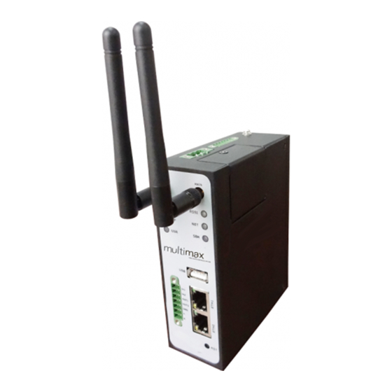
Chapter 1. Product Concept 1.1 Overview The Maxon Multimax MA-2040 is a rugged cellular router offering state-of-the-art mobile connectivity for machine to machine (M2M) applications. Dual SIM redundancy for continuous cellular connection supports 2G/3G/4G. n Optional diversity antenna for improved fringe performance. -
Page 11: Packing List
1.2 Packing List Check your package to make certain it contains the following items: Maxon Multimax MA-2040 router x 1 Ÿ 3-pin pluggable terminal block with lock for power connector x 1 Ÿ 7-pin pluggable terminal block with lock for serial port, I/O and console port x 1 Ÿ... - Page 12 Wall Mounting Kit Ÿ 35mm Din-Rail mounting kit Ÿ AC/DC Power Supply Adapter (12VDC, 1.5A) x 1 (EU, US, UK, AU plug optional) Ÿ MULTIMAX U SER G UIDE 11 ...
-
Page 13: Specifications
1.3 Specifications Cellular Interface Standards: GSM/GPRS/EDGE/UMTS/HSPA/FDD LTE n GPRS/EDGE: 850/900/1800/1900 MHz n HSUPA: 900/2100 or 850/1900 MHz optional, DL/UL 7.2/5.76 Mbps, fallback to 2G n HSPA+: 850/900/1900/2100 or 900/2100 or 850/1900 MHz optional, DL/UL 14.4/5.76 Mbps, n fallback to 2G FDD LTE: 800/900/1800/2100/2600 MHz or 700 MHz (B17 or B13) optional, DL/UL 100/50 Mbps, n... -
Page 14: Selection And Ordering Data
System LED Indicators: 6 indicators, RUN, PPP, USR, RSSI, NET, SIM n Built-in RTC, Watchdog, Timer n Expansion: 1 x USB 2.0 host up to 480 Mbps n Storage: 1 x MicroSD, can expand up to 2G n Software Network protocols: PPP, PPPoE, TCP, UDP, DHCP, ICMP, NAT, DMZ, RIP v1/v2, OSPF, DDNS, VRRP, n... -
Page 15: Chapter 2. Installation
Chapter 2. Installation 2.1 LED Indicators Name Color Function Indicating the system status. Blinking: Router is ready. Green On: Router is starting. Off: Router is power of. Indicating the PPP connection status. Green On: PPP connection is established. Off: PPP connection is failed. -
Page 16: Mounting The Router
2.2 Mounting the Router Use 2 pcs of M3 screw to mount the router on the wall. Or to mount the router on a DIN rail, you need three pcs of M3 screws. 2.3 Install the SIM Card and Micro SD Card ... - Page 17 Inserting SIM Card or Micro SD Card n Make sure power supply is disconnected. Use a screwdriver to unscrew the screw on the cover, and then remove the cover, you could find the SIM Card slots and the Micro SD slot. Insert the SIM card or Micro SD card, and you need press the card with your fingers until you hear “a cracking sound”.
-
Page 18: Connect The External Antenna (Sma Type)
2.4 Connect the External Antenna (SMA Type) Connect this to an external antenna with SMA male connector. Make sure the antenna is for the correct frequency as your GSM/3G/4G operator with impedance of 50ohm, and also connector is secured tightly. ... -
Page 19: Pin Assignment For Router
2.5 PIN assignment for Router RS23 Power Digital RS485 8 9 10 Positiv Negati 11 12 Input 1 13 Input 2 14 Output 15 16 Output 17 ... -
Page 20: Grounding The Router
2.6 Grounding the Router Grounding S crew Grounding and wire routing help limit the effects of noise due to electromagnetic interference (EMI). Run the ground connection from the ground screw to the grounding surface prior to connecting devices. Note: This product is intended to be mounted to a well-grounded mounting surface, such as a metal panel. -
Page 21: Chapter 3. Configuration Settings Over Web Browser
Chapter 3. Configuration settings over web browser The router can be configured through your web browser. A web browser is included as a standard application in the following operating systems: Linux, Mac OS, Windows 98 /NT /2000 /XP /Me /Vista /7 /8, etc. - Page 22 3. In the LAN Area Connection Status window, click Properties. 4. Select Internet Protocol (TCP/IP) and click Properties. MULTIMAX U SER G UIDE 21 ...
-
Page 23: Factory Default Settings
5. Select the Obtain an IP address automatically and Obtain DNS server address automatically radio buttons. 6. Click OK to finish the configuration. 3.2 Factory Default Settings Before configuring your router, you need to know the following default settings. Item Description Username... -
Page 24: Control Panel
3.3 Control Panel This section allows users to save configuration, reboot router, logout and select language. Control Panel Item Description Button Save Click to save the current configuration into router’s flash. After save the current configuration, router needs to be rebooted Reboot to make the modification taking effect. -
Page 25: Status -> System
3.4 Status -> System This section displays the router’s system status, which shows you a number of helpful information such as the LEDs information, Router information, Current WAN Link and Cellular Information. LEDs Information For the detail description, please refer to 2.2 LED Indicators. Router Information Item Description... - Page 26 Current WAN Link Item Description Current WAN Link Show the current WAN link: Cellular or Eth IP Address Show the current WAN IP address Gateway Show the current gateway Netmask Show the current netmask DNS Server Show the current primary DNS server and Secondary server Keeping PING IP Show the current ICMP detection server which you can set in Address...
- Page 27 4. Registration denied. 5. Registered, roaming. 6. Unknown. Signal Level (RSSI) Show the current signal level Show Mobile Country Code (MCC) +Mobile Network Code (MNC), Network Operator e.g. 46001. Also it will show the Location Area Code (LAC ) and Cell ID Network Service Type Show the current network service type, e.g.
-
Page 28: Status -> Network
3.5 Status -> Network This section displays the router’s Network status, which include status of Eth0 WAN and LAN1 Note: ETH0 WAN information will not be shown if you select “Cellular Only” in “Configuration”->”Link Management”->”WAN Link”. 3.6 Status -> Route This section displays the router’s route table. -
Page 29: Status -> Vpn
3.7 Status -> VPN This section displays the router’s VPN status, which include IPsec, L2TP, PPTP and OpenVPN. 28 MULTIMAX U SER G UIDE ... -
Page 30: Status -> Event/Log
3.8 Status -> Event/Log This section displays the router’s event/log information. You need to enable router to output the log and select the log level first, then you can view the log information here. 3.9 Configuration -> Link Management This section allows users to set the WAN link and the related parameters. Link Management Defa Item... -
Page 31: Configuration -> Cellular Wan
Retries Reset Enable to reset the cellular/ETH0 interface after the max ICMP detection Interface retries. 3.10 Configuration -> Cellular WAN This section allows users to set the Cellular WAN and the related parameters. Note: This section will not be displayed if you select “Eth0 Only” in “Configuration”->”Link Management”->”WAN Link”. - Page 32 requiring PIN or not. If you want to change the SIM PIN, please click the button to enable it, and then input the new PIN. Select from “Always Online” and “Connect On Demand”. Always Online: Router will automatically to establish a GPRS/3G connection after power on and each restarts, this will remain and will be re-established after an interruption.
- Page 33 Fails When Router will switch to backup SIM card when preferred SIM card is Roaming is Disable roaming. Detected The identifier for Router to check if it is in home location area or in Preferred roaming area, and decide if it needs to switch back to preferred SIM Null PLMN card.
- Page 34 Advanced Cellular WAN @Advanced Item Description Default Set the SIM card’s phone number, and it will be showed in “Status”->”System”->”System”->”Cellular WAN Information”-“SIM SIM Phone Phone Number”. Null Number In general, you don’t need to set this number because router will read it from the SIM card automatically.
- Page 35 Value modify this value. Use Peer DNS Enable to obtain the DNS server’s address from the ISP. Enable Primary DNS Set the primary DNS server’s address. This item will be unavailable if Null Server you enable “Use Peer DNS”. Secondary Set the secondary DNS server’s address.
-
Page 36: Configuration -> Ethernet
Password, Dialup No. 3.11 Configuration -> Ethernet This section allows users to set the Ethernet WAN and LAN parameters. Eth0/Eth1 Ethernet @ Eth0 Item Description Default Ethernet Eth0 can work under two different kinds of mode: LAN and WAN. Interface Type Enable Bridge Enable to make Eth0 works under bridge mode with Eth1. -
Page 37: Configuration -> Nat/Dmz
3.12 Configuration -> NAT/DMZ This section allows users to set the NAT/DMZ parameters. Port Forwarding Port Forwarding @ NAT/DMZ Defa Item Description Manually defining a rule in the router to send all data received on some Port range of ports on the internet side to a port and IP address on the LAN Null Forwarding... -
Page 38: Configuration -> Firewall
Arrives At The port of the internet side which you want to forward to LAN side. Null Port Is Forwarded The device’s IP on the LAN side which you want to forward the data to. Null to IP Address Is Forwarded The device’s port on the LAN side which you want to forward the data Null to Port... - Page 39 Access Using side via HTTP. HTTP Remote Enable to allow users to access the router remotely on the internet Access Using Enable side via Telnet. TELNET Remote Enable to allow users to access the router remotely on the internet Access Using Enable side via SNMP.
-
Page 40: Configuration -> Ip Routing
Select from “TCP”, “UDP”, “TCP&UDP”, “ICMP” or “ALL”. Protocol If you don’t know what kinds of protocol of your application, we recommend you select “ALL”. Note: You can use “-“ to define a range of IP addresses or ports, e.g. 1.1.1.1-2.2.2.2, 10000-12000. Mac-IP Bounding Mac-IP Bounding @ Firewall Item... - Page 41 RIP @ IP Routing Item Description Default RIP (Routing Information Protocol) is a distance-vector routing protocol, which employs the hop count as a routing metric. RIP Null prevents routing loops by implementing a limit on the number of hops allowed in a path from the source to a destination.
- Page 42 Enable Enable to make router send the default route to the other routers Default Disable which in the same IGP AS. Origination Enable Redistribute Redistribute connected routes into the RIP tables. Disable Connect Enable Redistributes routing information from static route entries into the RIP Redistribute Disable tables.
-
Page 43: Configuration -> Dyndns
OSPF OSPF @ IP Routing Item Description Default OSPF (Open Shortest Path First) is a link-state routing protocol for IP networks. It uses a link state routing algorithm and falls into the group OSPF Null of interior routing protocols, operating within a single autonomous system (AS). - Page 44 MULTIMAX U SER G UIDE 43 ...
-
Page 45: Configuration -> Ipsec
3.16 Configuration -> IPsec This section allows users to set the IPsec parameters. IPsec Basic IPsec Basic @ IPsec Item Description Default Enable NAT Tick to enable NAT Traversal for IPsec. This item must be enabled when Enable Traversal router under NAT environment. - Page 46 User FQDN: Uses a user FQDN type as the ID in IKE negotiation. If this option is selected, type a name string with an at sign (@) for the local security gateway, e.g., test@maxon.com. Remote Enter IPsec Remote Protected subnet’s address.
- Page 47 CA: Certification Authority. XAUTH: Extended Authentication to AAA server. Secrets Enter the Pre-shared Key. Null Set the lifetime in IKE negotiation. Life Time @ Before an SA expires, IKE negotiates a new SA. As soon as the 86400 new SA is set up, it takes effect immediately and the old one will Parameter...
- Page 48 Enable Tick to enable compressing the inner headers of IP packets. Disable Compress Please Click Add to add IPsec Tunnel Null IPsec Tunnel MULTIMAX U SER G UIDE 47 ...
- Page 49 X.509 X.509 @ IPsec Item Description Default Select Cert Select the IPsec tunnel which the certification used for. Null Type Click “Browse” to select the correct CA file from your PC, and then click “Import” to import it to the router. Null Click “Export”...
-
Page 50: Configuration -> Open Vpn
3.17 Configuration -> Open VPN This section allows users to set the Open VPN parameters. Client Client @ Open VPN Item Description Default Enable Enable OpenVPN Client, the max tunnel account is 3 Null Disable Disable IPsec Tunnel Client. Null OpenVPN_Tun Tunnel name Name the OpenVPN client. - Page 51 Maximum Transmission Unit. It is the identifier of the maximum size of packet, which is possible to transfer in a given 1500 environment. Max Frame Set the Max Frame Size for transmission. 1500 Size Select the log output level which from low to high: “ERR”, Verbose “WARNING”, “NOTICE”...
- Page 52 Server Server @ Open VPN Item Description Default Enable OpenVPN Tick to enable OpenVPN server tunnel. Disable Server Tunnel_OpenVP Tunnel name Name the OpenVPN server tunnel. You can enter the IP address of cellular WAN, Ethernet WAN or Listen IP Ethernet LAN.
- Page 53 Tick to enable NAT Traversal for OpenVPN. This item must be Enable NAT Disable enabled when router under NAT environment. Ping Interval Set ping interval to check if the tunnel is active. Restart to establish the OpenVPN tunnel if ping always timeout Ping -Restart during this time.
- Page 54 X.509 X.509 @ Open VPN Defa Item Description Select Cert Select the OpenVPN client or server which the certification used for. Null Type Click “Browse” to select the correct CA file from your PC, and then click “Import” to import it to the router. Null Click “Export”...
-
Page 55: Configuration -> L2Tp
Click “Export” you can export the TA file from router to your PC. Click “Browse” to select the correct CRL file from your PC, and then click “Import” to import it to the router. Null Click “Export” you can export the CRL file from router to your PC. Click “Browse”... - Page 56 You need to select the corresponding authentication method based on the server’s authentication method. When you select “Auto”, router will auto select the correct method based on servers. Enable Tunnel Tick to enable tunnel authentication and enter the tunnel secret Authenticatio Disable which provided by L2TP server.
- Page 57 Server L2TP Server @ L2TP Item Description Default Enable L2TP Tick to enable L2TP server. Disable Server Username Set the username which will assign to L2TP client. Null Password Set the password which will assign to L2TP client. Null Select from “PAP”, “CHAP”, “MS-CHAP v1”...
- Page 58 Enable L2TP Server Tick to show the L2TP server advanced setting. Disable Advanced Address/Control Used for PPP initialization. In general, you need to enable it as Enable Compression default. Protocol Field Used for PPP initialization. In general, you need to enable it as Enable Compression default.
-
Page 59: Configuration -> Pptp
3.19 Configuration -> PPTP This section allows users to set the PPTP parameters. Client PPTP Client @ PPTP Item Description Default Enable Enable PPTP Client. The max tunnel accounts are 3. Null Disable Disable PPTP Client. Null Server Name Enter your PPTP server’s public IP or domain name. - Page 60 Client Advanced Set the IP address of the PPTP client. You can enter the IP which assigned by PPTP server. Null means Local IP Null PPTP client will obtain an IP address automatically from PPTP server’s IP pool. Enter the remote peer’s private IP address or remote subnet’s Remote IP Null gateways address.
- Page 61 Server PPTP Server @ PPTP Item Description Default Enable PPTP Tick to enable PPTP server. Disable Server Username Set the username which will assign to PPTP client. Null Password Set the password which will assign to PPTP client. Null Select from “PAP”, “CHAP”, “MS-CHAP v1”...
- Page 62 Server Advanced Address/Cont Used for PPP initialization. In general, you need to enable it as default. Enable Compression Protocol Field Used for PPP initialization. In general, you need to enable it as default. Enable Compression Asyncmap One of the PPTP initialization strings. In general, you don’t need to ffffffff Value modify this value.
-
Page 63: Configuration -> Snmp
SNMPv2 Location Info Enter the router’s location info which will send to SNMP client. China info@maxon.c Contact Info Enter the router’s contact info which will send to SNMP client. System name Enter the router’s system name which will send to SNMP client. -
Page 64: Configuration -> Serial
View View @ SNMP Defa Item Description View Name Enter the View Name Null Inclu View Filter Select from “Include” and “Exclude”. View OID Enter the Object Identifiers (OID) Null VACM VACM @ SNMP Item Description Default Readwrite Select the access rights from “Readonly” and “ReadWrite”. Readonly Network Define the network from which is allowed to access. - Page 65 Flow control Select from “None”, “Software” and “Hardware”. None Select from “None”, “Transparent” and “Modbus”. Transparent: Router will transmit the serial data transparently Protocol without any protocols. None Modbus: Router will transmit the serial data with Modbus protocol.
- Page 66 Delimiter1/2 (Hex) Enter the delimiter in Hex. @Transparent The Delimiter process field determines how the data is handled when a delimiter is received. Delimiter Process None: Data in the buffer will be transmitted when the delimiter Strip @Transparent is received; the data also includes the delimiter characters. Strip: Data in the buffer is first stripped of the delimiter before being transmitted.
- Page 67 RS485 RS485 @ Serial Item Description Default Select from “300”, “600”, “1200”, “2400”, “4800”, “9600”, Baudrate 115200 “19200”, “38400”, “57600” , “115200”and “230400”. Data bit Select from “7” and “8”. Parity Select from “None”, “Odd” and “Even”. None Stop bit Select from “1”...
- Page 68 Transparent: Router will transmit the serial data transparently without any protocols. Modbus: Router will transmit the serial data with Modbus protocol. Mode Select from “TCP Server”, “TCP Client” and “UDP”. TCP Client @Transparent Local Port Enter the Local port for TCP or UDP. @Transparent Click “Add”...
- Page 69 Strip: Data in the buffer is first stripped of the delimiter before being transmitted. Local Port @ Enter the Local port for Modbus. Modbus Select From “Modbus RTU slave”, “Modbus ASCⅡ slave”, “Modbus RTU master” and “Modbus ASCⅡ master”. Modbus RTU slave: router connects to slave device which Attached works under Modbus RTU protocol.
-
Page 70: Configuration -> Vrrp
3.22 Configuration -> VRRP This section allows users to set the VRRP parameters. VRRP Item Description Default Tick to enable VRRP protocol. VRRP (Virtual Router Redundancy Protocol) is an Internet protocol that provides a way to have one Enable VRRP or more backup routers when using a statically configured router Disable on a local area network (LAN).Using VRRP, a virtual IP address can... -
Page 71: Configuration -> At Over Ip
designated as the master router and the others as backups. In .0.1 case the master fails, the virtual IP address is mapped to a backup router's IP address. (This backup becomes the master router.) 3.23 Configuration -> AT over IP This section allows users to set the AT over IP parameters. -
Page 72: Configuration -> Syslog
Reboot Time1 Specify time1 when you need router reboot. Null Reboot Time2 Specify time2 when you need router reboot. Null Reboot Time3 Specify time3 when you need router reboot. Null 3.25 Configuration -> Syslog This section allows users to set the syslog parameters. Syslog Item Description... -
Page 73: Administration -> Profile
3.27 Administration -> Profile This section allows users to import or export the configuration file, and restore the router to factory default setting. Profile Item Description Default Import: Click “Browse” to select the XML file in your computer, then click “Import”... -
Page 74: Administration -> Tools
3.28 Administration -> Tools This section provides users three tools: Ping, AT Debug and Traceroute. Ping Ping Item Description Default Ping IP address Enter the ping destination IP address or domain name. Null Number of Specify the number of requests. requests Timeout Specify timeout of ping request. - Page 75 AT Debug AT Debug Item Description Default Send AT Enter the AT commands which you need to send to cellular Null Commands module in this box. Send Click this button to send the AT commands. Null Receive AT Router will display the AT commands which respond from the Null Commands...
-
Page 76: Administration -> User Management
Traceroute Item Description Default Trace Address Enter the trace destination IP address or domain name. Null Specify the max trace hops. Router will stop tracing if the trace Trace Hops hops has met max value no matter the destination has been reached or not. -
Page 77: Administration -> Clock
Common Common @ User Management Item Description Default One router has at most 9 common user accounts. There are two Common access level of common user account: “ReadWrite” and Null “ReadOnly”. Select from “ReadWrite” and “ReadOnly”. ReadWrite: Users can view and set the configuration of router Access Level under this level;... -
Page 78: Administration -> Update Firmware
from NTP server. Timezone @ Client Select your local time zone. +08:00 pool.ntp Primary NTP Server Enter primary NTP Server’s IP address or domain name. .org Secondary NTP Enter secondary NTP Server’s IP address or domain name. Null Server Update interval Enter the interval which NTP client synchronize the time from NTP server. -
Page 79: Chapter 4. Examples Of Configuration
Chapter 4. Examples of configuration 4.1 Cellular Dial-Up This section shows users how to configure the parameters of Cellular Dial-up which are with two different policies “Always Online” and “Connect on Demand”. Note: This section will be hidden if user selects “Eth0 Only” in “Configuration ->Link Management”. 4.1.1 Always Online: Configuration-->Link Management-->Cellular Only The modifications will take effect after click “Apply”... - Page 80 The modifications will take effect after click “Apply” button. If a customized SIM card is using, please select “Custom” instead of “Auto” in “Network Provider Type”, and some relative settings should be filled in manually. 4.1.2 Connect on Demand: Configuration-->Link Management-->Cellular Only The modifications will take effect after click “Apply”...
-
Page 81: Nat
Configuration-->Cellular WAN -->Basic Select the trigger policy you need. Note: If you select multiple trigger policies, the router will be triggered under anyone of them. 4.2 NAT This section shows users how to set the NAT configuration of router. Parameter Remote IP defines if access is allowed to route to the Forwarded IP and Port via WAN IP and “Arrives At Port”. - Page 82 Configuration--->NAT/DMZ--->Port Forwarding Note: This section will be hidden if user selects “Cellular as primary and if fail use Eth0” in “Configuration ->Link Management”. Explanations for above diagram: If there are two IP addresses 58.1.1.1 and 59.1.1.1 for the External Devices, that the result will be different from the test when the NAT is working at MA-2040.
-
Page 83: L2Tp
4.3 L2TP Note: The following diagrams with red color numbers mean these are the matches between server and client, and with the blue color number means it must be set locally for the tunnel. L2TP_SERVER: Configuration--->L2TP--->L2TP Server Tick “Enable L2TP Server”, and fill in the blank textbox ... - Page 84 The modification will take effect after “Apply-->Save-->Reboot”. L2TP_CLIENT: Configuration--->L2TP--->L2TP Client Click “Add” button, and fill in the blank textbox The modification will take effect after “Apply-->Save-->Reboot”. MULTIMAX U SER G UIDE 83 ...
-
Page 85: Pptp
4.4 PPTP Note: The following diagrams with red color numbers mean these are the matches between server and client, and with the blue color number means it must be set locally for the tunnel. PPTP_SERVER: Configuration--->PPTP--->PPTP Server Tick “Enable PPTP Server”, and fill in the blank textbox ... -
Page 86: Ipsec Vpn
The modification will take effect after “Apply-->Save-->Reboot”. PPTP_CLIENT: Configuration--->PPTP--->PPTP Client Click “Add” button, and fill in the blank textbox The modification will take effect after “Apply-->Save-->Reboot”. 4.5 IPSEC VPN Note: The following diagrams with red color numbers mean these are the matches between server and client, and with the blue color number means it must be set locally for the tunnel. - Page 87 IPsecVPN_SERVER: Cisco 2811: Note: Polices 1,4,6,7 are default for Cisco router and do not display at the CMD. IPsecVPN_CLIENT: Configuration--->IPsec--->IPsec Basic Then click “Apply”. Configuration--->IPsec--->IPsec Tunnel Tick “Enable IPsec Tunnel1” 86 MULTIMAX U SER G UIDE ...
- Page 88 The modification will take effect after “Apply-->Save-->Reboot”. MULTIMAX U SER G UIDE 87 ...
-
Page 89: Openvpn
4.6 OPENVPN Note: The following diagrams with red color numbers mean these are the matches between server and client, and with the blue color number means it must be set locally for the tunnel. OPENVPN_SERVER: Configuration--->OpenVPN--->Server Tick “Enable OpenVPN Server”. ... - Page 90 The modifications will take effect after click “Apply-->Save-->Reboot”. MULTIMAX U SER G UIDE 89 ...
- Page 91 OPENVPN_CLIENT: Configuration--->OpenVPN--->Client Tick “Enable OpenVPN Client1”, and fill in the blank textbox The modification will take effect after “Apply-->Save-->Reboot”. 90 MULTIMAX U SER G UIDE ...
-
Page 92: Chapter 5. Introductions For Cli
Chapter 5. Introductions for CLI 5.1 What’s CLI and hierarchy level Mode The MA-2040 command-line interface(CLI) is a software interface providing our another way to set the parameters of equipment from the console or through a telnet network connection. Before using them better a few of details will be introduced on four different CLI hierarchy level modes which have different access rights: l... - Page 93 PRIVILEDGED EXEC MODE: MA-2040> enable Password: ***** MA-2040# ? //check what commands can be used in priviledged exec mode Debug Debug configure information Enable Turn on privileged commands Exit Exit from current mode Export Export file using tftp Syslog Export system log import...
- Page 94 INTERFACE MODE: MA-2040(config)# interface Ethernet 0 //check what commands can be used in interface mode MA-2040(config-e0)# ? exit Exit from current mode Exit to normal mode Set the IP address of an interface Set the IP address of an interface 5.2 How to configure the CLI Following is a list about the description of help and the error should be encountered in the configuring program.
- Page 95 5.2.1 Quick Start with configuration examples The best and quickest way to master CLI is firstly to view all features from the webpage and then reading all CLI commands at a time ,finally learn to configure it with some reference examples . Example 1 : Show current version MA-2040>...
- Page 96 ->ICMP detection retries(1-20)[3]: ->reset the interface?'yes'or'no'[no]: this parameter will be take effect when reboot! really want to modify[yes]: MA-2040# write //save current configuration Building configuration... MA-2040# reload !Reboot the system ?'yes'or 'no':yes //reload to take effect Example 4: Set IP address, Gateway and DNS for Eth0 MA-2040>...
- Page 97 MA-2040# write //save current configuration Building configuration... MA-2040# reload !Reboot the system ?'yes'or 'no':yes //reload to take effect Example 5: CLI for Cellular dialup MA-2040> enable Password: ***** MA-2040# MA-2040# show link-management ********************************************* wan link : Cellular Only // now “Cellular Only”...
- Page 98 1. Always online 2. Connect on demand ->please select mode(1-2)[1]: ->redial interval(1-120)[30]: ->max connect try(1-60)[3]: MA-2040(config)# end MA-2040# write //save current configuration Building configuration... MA-2040# show cellular ************************************************* Cellular enable : yes 1. show SIM_1 parameters 2. show SIM_2 parameters ->please select mode(1-2)[1]: SIM 1 parameters: network provider...
- Page 99 5.3 Commands reference commands syntax description Debug Debug parameters Turn on or turn off debug function Export Export parameters Export vpn ca certificates Import Import parameters Import vpn ca certificates Syslog syslog Export log information to tftp server Load Load default Restores default values...
Need help?
Do you have a question about the MULTIMAX MA 2040 and is the answer not in the manual?
Questions and answers