Table of Contents
Advertisement
Quick Links
SERVICE MANUAL
Dolby noise reduction manufactured under license
from Dolby Laboratories Licensing Corporation.
"DOLBY" and the double-D symbol a are trademarks
of Dolby Laboratories Licensing Corporation.
MICROFILM
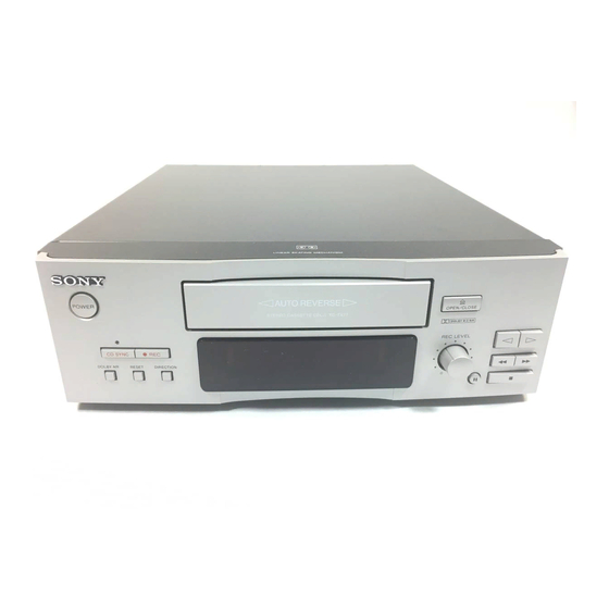
TC-TX77
Model Name Using Similar Mechanism
Tape Transport Mechanism Type
SPECIFICATIONS
STEREO CASSETTE DECK
AEP Model
UK Model
TC-S1
TCM-9700HLD
Advertisement
Table of Contents

Subscribe to Our Youtube Channel
Related Manuals for Sony tc-tx77


Summary of Contents for Sony tc-tx77
- Page 1 TC-TX77 SERVICE MANUAL AEP Model UK Model Dolby noise reduction manufactured under license Model Name Using Similar Mechanism TC-S1 from Dolby Laboratories Licensing Corporation. Tape Transport Mechanism Type TCM-9700HLD “DOLBY” and the double-D symbol a are trademarks of Dolby Laboratories Licensing Corporation.
-
Page 2: Table Of Contents
LINE WITH MARK ! ON THE SCHEMATIC DIAGRAMS AND IN THE PARTS LIST ARE CRITICAL TO SAFE OPERATION. REPLACE THESE COMPONENTS WITH SONY PARTS WHOSE PART NUMBERS APPEAR AS SHOWN IN THIS MANUAL OR IN SUPPLEMENTS PUB- LISHED BY SONY. -
Page 3: General
SECTION 1 This section is extracted from instruction manual. GENERAL – 3 –... -
Page 4: Disassembly
SECTION 2 DISASSEMBLY • This set can be disassembled in the order shown below. COVER, FRONT PANEL SECTION MECHANISM DECK (TCM-9700HLD) MOTOR (HK) ASS’Y (M902) (Page 4) (page 5) (Page 6) AUDIO/CONNECTOR BOARD, POWER TRANSFORMER (T901) (Page 5) TRAY (A) ASS’Y (Page 6) Note: Follow the disassembly procedure in the numerical order given. - Page 5 3 two screws MECHANISM DECK (TCM-9700HLD) (BVTP3 × 8) 1 connector (CN804) 4 lag 5 mechanism deck (TCM-9700HLD) 1 connector (CN803) 1 connector (CN351) 2 two screws (BVTP3 × 8) AUDIO/CONNECTOR BOARD, POWER TRANSFORMER (T901) 1 power cord (CN901) 6 power thansformer 5 connector (T901) (CN701)
- Page 6 TRAY (A) ASS’Y 2 two claws tray (A) ass’y 3 tray (A) ass’y 1 Rotate the gear ass’y in direction arrow A to up the tray. tray MOTOR (HK) ASS’Y (M902) 6 motor (HK) ass’y (M902) 4 Remove the solders of motor (M902).
-
Page 7: Mechanical Adjustments
SECTION 3 SECTION 4 ELECTRICAL ADJUSTMENTS MECHANICAL ADJUSTMENTS PRECAUTION PRECAUTION 1. Clean the following parts with a denatured-alcohol-moistened 1. The adjustment should be performed in the publication. swab: (Be sure to male playback adjustment at first.) record/playback/earth head pinch roller 2. - Page 8 Record/Playback Head Azimuth Adjustment Tape Speed Adjustment Procedure: Procedure: 1. Mode: REV playback Mode: FWD playback test tape test tape P-4-A100 WS-48B level meter frequency counter (3 kHz, 0 dB) (10 kHz, – 10 dB) 47 k Ω 47 k Ω –...
- Page 9 Record BIAS Adjustment Record Level Adjustment Setting: Setting: REC LEVEL control: Standard record position (See page 7) REC LEVEL control: Standard record position (See page 7) Set to the TEST mode (REC MEMORY mode). (See page 7) Set to the TEST mode (REC MEMORY mode). (See page 7) Procedure: Procedure: 1.
- Page 10 • Adjustment Parts Location [AUDIO BOARD] (Component Side) CN714 RV151 Playback Level (L-CH) RV251 Playback Level (R-CH) CN711 CN351 IC301 IC304 RV252 Record Bias (R-CH) RV253 RV153 Record Level (R-CH) RV152 Record Level (L-CH) Record Bias (L-CH) [SYSTEM CONTROL BOARD] (Component Side) RV801 Tape Speed CN803...
-
Page 11: Ic Pin Function Description
SECTION 5 DIAGRAMS 5-1. IC PIN FUNCTION DESCRIPTION SYSTEM CONTROL BOARD IC801 M38172M4-150FP (SYSTEM CONTROL) Pin No. Pin Name Function METER-R Digital peak level meter signal input (R-ch) METER-L Digital peak level meter signal input (L-ch) KEY-Y Key input (A/D convert input) *1 KEY-X FWD-TAB Record proof detection input from S902 (FWD side) “H”: Not nail... - Page 12 Pin No. Pin Name Function Segment signal output to fluorescent indicator tube (FLT851) Grid Signal output to fluorescent indicator tube (FLT851) TYPE 1 Tape type output “H”: Normal position TYPE 2 Tape type output “H”: High position TYPE 4 Tape type output “H”: Metal position —...
-
Page 16: Exploded Views
Description Remark 4-985-926-01 KNOB 3-939-653-01 LID (R-TC) X-3372-679-1 PANEL ASSY, FRONT 3-363-099-01 SCREW (CASE 3 TP2) 4-962-708-01 EMBLEM (4-A), SONY * 11 3-939-652-11 COVER 3-939-648-01 WINDOW (TC) * 12 A-2007-717-A PANEL BOARD, COMPLETE 3-939-646-01 BUTTON (REC) (CD SYNC. r REC) 3-939-643-01 BUTTON (FF) (0. - Page 17 (2) CHASSIS SECTION TCM-9700HLD not supplied T901 not supplied not supplied The components identified by mark ! or dotted line with mark ! are critical for safety. Replace only with part number specified. Ref. No. Part No. Description Remark Ref. No. Part No.
- Page 18 (3) MECHANISM DECK SECTION-1 (TCM-9700HLD) supplied M901 S901 Ref. No. Part No. Description Remark Ref. No. Part No. Description Remark A-2004-430-A TRAY (A) ASSY X-3369-090-1 GEAR ASSY A-2004-429-A CLAMP (B) ASSY 3-918-629-01 SPRING (A), COMPRESSION 3-917-502-01 SCREW (2X8), +BTT 3-918-630-01 WASHER, FLAT 3-917-501-01 SPRING, TOGGLE 3-917-496-01 CHASSIS (MAIN) 3-917-498-01 SCREW (2.6X6), +BTT...
- Page 19 (4) MECHANISM DECK SECTION-2 (TCM-9700HLD) HRPE901 not supplied not supplied not supplied not supplied supplied not supplied not supplied PM901 Ref. No. Part No. Description Remark Ref. No. Part No. Description Remark A-2004-436-A GEAR ASSY, PLAY 3-917-530-01 SPRING (RETURN), TOGGLE 3-917-549-01 ARM, PLAY 3-917-534-01 WASHER, POLY-SLIDER 3-917-553-01 SPRING (PLAY ARM), TOGGLE...
- Page 20 (5) MECHANISM DECK SECTION-3 (TCM-9700HLD) M902 supplied supplied supplied supplied not supplied Ref. No. Part No. Description Remark Ref. No. Part No. Description Remark 3-917-608-01 BELT (HK-3), DRIVE 3-917-604-01 WASHER, POLY-SLIDER X-3369-099-1 CLUTCH (HK) ASSY 3-701-437-11 WASHER 3-917-599-01 WASHER, POLY-SLIDER 3-917-623-01 CUSHION, MOTOR RUBBER * 204 X-3369-098-1 BASE (HK) ASSY, MECHANICAL...
-
Page 21: Electrical Parts List
SECTION 7 AUDIO ELECTRICAL PARTS LIST NOTE: • Due to standardization, replacements in the • Items marked “*” are not stocked since they The components identified by mark are seldom required for routine service. parts list may be different from the parts speci- ! or dotted line with mark ! are fied in the diagrams or the components used on Some delay should be anticipated when order-... - Page 22 AUDIO Ref. No. Part No. Description Remark Ref. No. Part No. Description Remark D302 8-719-987-63 DIODE 1N4148M Q354 8-729-194-57 TRANSISTOR 2SC945-P D303 8-719-987-63 DIODE 1N4148M Q355 8-729-194-57 TRANSISTOR 2SC945-P D351 8-719-987-63 DIODE 1N4148M D352 8-719-987-63 DIODE 1N4148M Q356 8-729-900-80 TRANSISTOR DTC114ES Q357 8-729-900-80 TRANSISTOR DTC114ES D353...
- Page 23 AUDIO CONNECTOR Ref. No. Part No. Description Remark Ref. No. Part No. Description Remark R203 1-249-429-11 CARBON 1/4W R708 1-249-427-11 CARBON 6.8K 1/4W R204 1-249-421-11 CARBON 2.2K 1/4W R709 1-249-419-11 CARBON 1.5K 1/4W R710 1-249-429-11 CARBON 1/4W R205 1-247-843-11 CARBON 3.3K 1/4W R206...
- Page 24 CONNECTOR MECH PANEL PRIMARY SYSTEM CONTROL Ref. No. Part No. Description Remark Ref. No. Part No. Description Remark R719 1-249-429-11 CARBON 1/4W R856 1-249-413-11 CARBON 1/4W R720 1-249-437-11 CARBON 1/4W R857 1-249-417-11 CARBON 1/4W R721 1-249-435-11 CARBON 1/4W R858 1-249-421-11 CARBON 2.2K 1/4W R859...
- Page 25 SYSTEM CONTROL TRANS Ref. No. Part No. Description Remark Ref. No. Part No. Description Remark < DIODE > R825 1-249-429-11 CARBON 1/4W R826 1-249-429-11 CARBON 1/4W D712 8-719-987-63 DIODE 1N4148M D801 8-719-933-33 DIODE HZS6A1L R827 1-249-419-11 CARBON 1.5K 1/4W D802 8-719-933-33 DIODE HZS6A1L R828 1-249-417-11 CARBON...
- Page 26 Ref. No. Part No. Description Remark ACCESSORIES & PACKING MATERIALS ******************************* 1-558-271-11 CORD, CONNECTION (AUDIO 1.0m) 1-574-314-11 CORD (WITH CONNECTOR) (AU BUS) 3-860-361-11 MANUAL, INSTRUCTION (ENGLISH, FRENCH, SPANISH, PORTUGUESE) (AEP, UK) 3-860-361-21 MANUAL, INSTRUCTION (GERMAN, DUTCH, SWEDISH, ITALIAN) (AEP) – 33 –...
- Page 27 TC-TX77 Sony Corporation 97E057553-1 9-960-774-11 Printed in Hungary © 1997. 5 Home A&V Products Company Published by General Engineering Dept. – 34 – (Shibaura)
Need help?
Do you have a question about the tc-tx77 and is the answer not in the manual?
Questions and answers