Table of Contents
Advertisement
Advertisement
Table of Contents

Related Manuals for A10 Thunder series 930


Summary of Contents for A10 Thunder series 930
- Page 1 INSTALLATION GUIDE A10 Thunder Series 930 ADC 26 January 2015...
-
Page 2: Environmental Considerations
Disclaimer This document does not create any express or implied warranty about A10 Networks or about its products or services, including but not limited to fitness for a particular use and non-infringement. A10 Networks has made reasonable efforts to verify that the information contained herein is accurate, but A10 Networks assumes no responsibility for its use. -
Page 3: Table Of Contents
Table of Contents Hardware Warnings, Cautions, and Requirements ............5 Getting Started ..........................9 Inspection ................................9 Interface Connections ............................10 LED Locations and Status Indicators ......................11 Installation ................................12 Power-On................................13 Power Supply Unit Installation ....................15 Overview ................................15 DC Power Supply Installation........................17 Power Supply Hot Swap..........................19 Removing a Power Supply ............................ - Page 4 A10 Thunder Series 930 Installation Guide Contents Sliding Rail Kit Installation ......................31 Getting Started..............................31 Rail Kit Contents ................................... 31 Required Tools ..................................31 Sliding Rail Kit Installation..........................32 Attach the Mounting Brackets ............................ 32 Install the Inner Rails ................................. 33 Remove the Inner Rails ............................33 Attach the Inner Rails to the Chassis ......................
-
Page 5: Hardware Warnings, Cautions, And Requirements
Hardware Warnings, Cautions, and Requirements Please carefully read all the following statements before beginning installation. (Note that some statements might not apply to your product.) Chassis Lifting and Placement Lifting the chassis and placing it in the rails is a two-person job. If needed, use an appropriate lifting device. -
Page 6: Reliable Earthing
A10 Thunder Series 930 Installation Guide Reliable Earthing Reliable earthing of rack-mounted equipment should be maintained. Particular attention should be given to supply connections other than direct connections to the branch circuit. For example, make sure earthing is maintained even if you use power strips. -
Page 7: Preparing The Site
A10 Thunder Series 930 Installation Guide Preparing the Power Input Observe the following: • The DC Option Power return leads must be configured in the DC-Isolated (DC-I) config- uration. The DC Return connection must remain isolated from ground until it is con- nected to the Central Office Power source return Bus. - Page 8 A10 Thunder Series 930 Installation Guide Document No.: TH-930-001 - 1/26/2015 | page 8...
-
Page 9: Getting Started
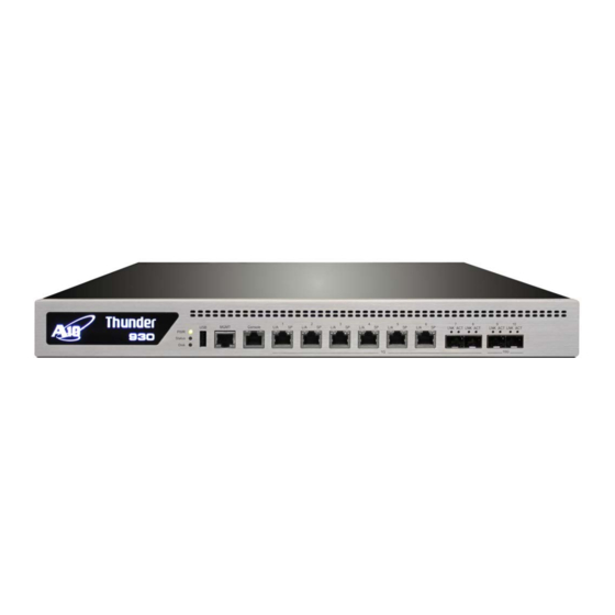
Getting Started This guide describes how to physically install the A10 Thunder Series 930 ADC model, and how to configure the MGMT (management) interface for network access to the Command-Line Interface (CLI). FIGURE 1 Thunder 930 (Front Panel View) Inspection Inspect the box carefully before opening it. -
Page 10: Interface Connections
A10 Thunder Series 930 Installation Guide Interface Connections Specifications for the equipment rack are listed in Table Rack-mount installation instructions are available in “Rack Mount Kit Installation” on page Sliding rail installation instructions are available in “Sliding Rail Kit Installation” on page •... -
Page 11: Led Locations And Status Indicators
A10 Thunder Series 930 Installation Guide LED Locations and Status Indicators FIGURE 2 Interface Locations and Numbers #7 #8 #9 #10 1 GB Copper Data Interfaces 1 GB Fiber Data Interfaces Management Console 10 GB Fiber Data Interfaces To begin using these interface connections: 1. -
Page 12: Installation
A10 Thunder Series 930 Installation Guide Installation Table 1 describes the LED status indicators. TABLE 1 LED Status Indicators Color Status Description Green Power is switched ON No power connected Amber Flash Post BIOS STAT Green Flash System under access... -
Page 13: Power-On
A10 Thunder Series 930 Installation Guide Power-On Item Rack Mount Kit Sliding Rail Kit Supported Models AX1030, AX3030, AX930 AX1030, AX3030, AX930 TH1030S, TH3030S, TH930 TH1030S, TH3030S, TH930 2-Post Installation? 4-Post Installation? 4-Post Depth 31 inches 36 inches Mounting Thread... - Page 14 A10 Thunder Series 930 Installation Guide Power-On Document No.: TH-930-001 - 1/26/2015 | page 14...
-
Page 15: Power Supply Unit Installation
Power Supply Unit Installation This guide describes how to connect the power supply unit to an applicable AC or DC power source. The following topics are covered: Overview • DC Power Supply Installation • Power Supply Hot Swap • CAUTION: Do not attempt to install or operate damaged equipment. - Page 16 A10 Thunder Series 930 Installation Guide Overview FIGURE 4 Example of AC Power Supply FIGURE 5 Example of DC Power Supply Document No.: TH-930-001 - 1/26/2015 | page 16...
-
Page 17: Dc Power Supply Installation
A10 Thunder Series 930 Installation Guide DC Power Supply Installation FIGURE 6 Example of DC Power Supply (Assembled - Cable Inserted) DC Power Supply Installation Refer to the following instructions and figures for this procedure. (Also see figures on previous page.) NOTE: Use at least a 20-amp fuse for each DC breaker. - Page 18 A10 Thunder Series 930 Installation Guide DC Power Supply Installation FIGURE 7 Connecting the DC Power Supply Cable Document No.: TH-930-001 - 1/26/2015 | page 18...
-
Page 19: Power Supply Hot Swap
A10 Thunder Series 930 Installation Guide Power Supply Hot Swap FIGURE 8 DC Power Supply Cables Power Supply Hot Swap Follow the directions in the following sections to remove and insert a power supply unit. FIGURE 9 Power Supply Hot Swap... -
Page 20: Removing A Power Supply
A10 Thunder Series 930 Installation Guide Power Supply Hot Swap Removing a Power Supply To remove a power supply: 1. Push and hold the panel to unlock the lock (A). 2. Hold the panel and pull out the power supply... -
Page 21: Initial Configuration
Initial Configuration This chapter describes how to perform the initial configuration for a new ACOS device. The following topics are covered: Management Interface Configuration • Configuring a New ACOS Device Using an Existing Configuration • NOTE: If you are planning to configure the new ACOS device by loading the configuration from another ACOS device, see “Configuring a New ACOS Device Using an Existing Configura- tion”... -
Page 22: Connection Via Console (Serial Port)
3. Set the terminal emulation software for 9600 baud and 8-N-1 (8 bits - no parity - 1 stop bit). Once you are connected, the login prompt will display on the terminal. Login via CLI 1. Log into the ACOS device with the default username admin and the default password a10. admin login as: Welcome to ACOS Using keyboard-interactive authentication. -
Page 23: Change The Admin Password
Automated Management Traffic” chapter in the System Configuration and Administra- tion Guide. Change the Admin Password A10 Networks recommends that you change the admin password immediately for security. ACOS(config)#admin admin password newpassword ACOS(config-admin:admin)# The ACOS device is now network accessible for configuration under the new IP address and admin password. -
Page 24: Save The Configuration Changes
A10 Thunder Series 930 Installation Guide Configuring a New ACOS Device Using an Existing Configuration Save the Configuration Changes Configuration changes made so far must be saved to the system memory to take effect when the system reboots. Otherwise, a power interruption (for example) could cause the system to be unavailable from the Web interface, in which case the con- sole configuration would need to be repeated. -
Page 25: Fan Hot Swap
Fan Hot Swap This chapter provides fan hot swap instructions for the device. To determine the fan tray that needs to be replaced, run the show environment command from the CLI. The following topics are covered: Fan Module Location and Fan Numbers •... -
Page 26: Inserting A Fan Module
A10 Thunder Series 930 Installation Guide Inserting a Fan Module FIGURE 11 Removing a Fan Module 1. Loosen both screws on the right side of the module. 2. Use this handle to pull the fan module out. Inserting a Fan Module Follow the steps below in order to remove a fan module. -
Page 27: Rack Mount Kit Installation
The following devices are shipped with screws on the side of the chassis, to be used in conjunction with the new screwless sliding rail kit: - A10 Thunder Series 5330(S) - A10 Thunder Series 3430(S) - A10 Thunder Series 3230(S) If you are installing the rack mount kit for any of these devices, you must first remove these pre-installed screws before continuing. -
Page 28: Front Mount Installation
A10 Thunder Series 930 Installation Guide Front Mount Installation Front Mount Installation This section provides instructions for a front-mount installation. 1. Align a bracket over the 6 black 4-mm flat-head screws that will be used to attach the bracket to the chassis. Make sure to use the correct bracket. -
Page 29: Center Mount Installation
A10 Thunder Series 930 Installation Guide Center Mount Installation Center Mount Installation This section provides instructions for a center mount installation. 1. Align a bracket over the 6 black 4-mm flat-head screws that will be used to attach the bracket to the chassis. Make sure to use the correct bracket. - Page 30 A10 Thunder Series 930 Installation Guide Center Mount Installation Document No.: TH-930-001 - 1/26/2015 | page 30...
-
Page 31: Sliding Rail Kit Installation
Sliding Rail Kit Installation This chapter contains instructions for installing the sliding rail kit for your ACOS device. The following topics are covered: Getting Started • Sliding Rail Kit Installation • Getting Started This section contains the following topics: Rail Kit Contents •... -
Page 32: Sliding Rail Kit Installation
A10 Thunder Series 930 Installation Guide Sliding Rail Kit Installation Sliding Rail Kit Installation Installation consists of the following tasks: Attach the Mounting Brackets • Install the Inner Rails • Attach the Outer Rails to the Rack Posts • Install the Chassis on the Rails •... -
Page 33: Install The Inner Rails
A10 Thunder Series 930 Installation Guide Sliding Rail Kit Installation Install the Inner Rails Perform the following steps for each inner rail.: Remove the Inner Rails Attach the Inner Rails to the Chassis Remove the Inner Rails To remove the inner rails: 1. -
Page 34: Attach The Outer Rails To The Rack Posts
A10 Thunder Series 930 Installation Guide Sliding Rail Kit Installation 3. Repeat for the other inner rail. Attach the Outer Rails to the Rack Posts To attach the outer rails to the rack posts: 1. Align the top and bottom screw holes at the front of the middle rail assembly behind 2 screw holes in the front of the rack. - Page 35 A10 Thunder Series 930 Installation Guide Sliding Rail Kit Installation 2. Insert 3 screws and partially tighten them. Optionally, you can use the silver flat-head screws and washers supplied with the rail kit. NOTE: If you plan to use your own screws, please make sure they are not too long to fit into the rail.
-
Page 36: Install The Chassis On The Rails
A10 Thunder Series 930 Installation Guide Sliding Rail Kit Installation 7. Repeat for the other outer rail. Install the Chassis on the Rails To install the chassis on the rails: CAUTION: Lifting the chassis and placing it in the rails is a two-person job. If needed, use an appro- priate lifting device. - Page 37 A10 Thunder Series 930 Installation Guide Sliding Rail Kit Installation 4. Press the finger tab located near the front of the chassis. You can push the tab in either direction. This unlocks the rails so you can slide the chassis into the rack.
- Page 38 A10 Thunder Series 930 Installation Guide Sliding Rail Kit Installation Document No.: TH-930-001 - 1/26/2015 | page 38...
-
Page 39: Power Supply Product Specifications
Power Supply Product Specifications The A10 Thunder Series 930 device is compatible with the power supply units described in this chapter: 600W AC Power Supply Specifications • 1100W DC Power Supply Specifications • 600W AC Power Supply Specifications Table 3 lists the specifications for the AC power supply. -
Page 40: 1100W Dc Power Supply Specifications
Item Specifications Part Number ASK-PSDC-010 Chassis compatibility A10 Thunder Series 6630, 6435(S), 5630, 5435(S), 5430S, 5430-11, 6430(S), 5330, 4435(S), 4430, 3430, 3230, 3030S, 1030S, 930 Power Supply Output 1100W 80 Plus Platinum. Warning Method Power Defective signal delivery warning to the Software. (TTL, Low active). -
Page 41: Additional Documentation And Rma Information
Feature information is available for ACOS products in the following documents. These documents are included on the docu- mentation CD shipped with your product, and also are available on the A10 Networks support site. For feature information, see the following guides: Basic Setup •... -
Page 42: Return Materials Authorization (Rma) And Customer Support
A10 Thunder Series 930 Installation Guide Return Materials Authorization (RMA) and Customer Support Return Materials Authorization (RMA) and Customer Support If you encounter any issues with your hardware and are unable to troubleshoot to a successful resolution, contact customer support using the information in this section. They will be able to assist you with return authorization and instructions. - Page 43 A10 Thunder Series 930 Installation Guide page 43 | Document No.: TH-930-001 - 1/26/2015...
- Page 44 Document No.: TH-930-001 | 1/26/2015...
Need help?
Do you have a question about the Thunder series 930 and is the answer not in the manual?
Questions and answers