
Related Manuals for Diatron Abacus Junior Vet


Summary of Contents for Diatron Abacus Junior Vet
- Page 1 UM-AJV-01-276 Abacus Junior Vet User’s Manual REVISION-HISTORY Date Name Signature Issued 06/10/2009 Ildiko Losonczi Checked and approved 06/10/2009 Csaba Magyar...
- Page 2 Hematology Analyzer User‟s Manual 2.76 release...
-
Page 3: Table Of Contents
TABLE OF CONTENTS INTRODUCTION ....................1-1 Intended Use ......................1-1 The Instrument ......................1-1 1.2.1 Patient Testing......................1-2 1.2.2 Reagents ........................1-3 1.2.3 Technical Operation ....................1-3 1.2.4 Calibration and Quality Control ................1-3 Instrument features....................1-4 Parts of the Analyzer ....................1-7 1.4.1 Function of the Fluidics .................. - Page 4 OPERATING PRINCIPLES ................4-1 Impedance Method ....................4-1 Principle of HGB Measurement ................4-1 Parameters ......................... 4-2 Absolute and Linearity Ranges of Measured Parameters ........4-3 ROUTINE UTILIZATION AND MEASURE ..........5-1 Sample handling ......................5-1 Sample analysis ......................5-4 5.2.1 Sample preparation ....................5-4 5.2.2 Modifying lyse quantity ..................
- Page 5 7.3.1 QC database ......................7-11 Diagnostics ....................... 7-12 7.4.1 Device statistics..................... 7-13 7.4.2 Self test ........................7-13 Settings ........................7-14 7.5.1 Printer Settings ...................... 7-14 7.5.1.1 Troubleshooting guide for printing problems ..........7-19 7.5.2 Customize......................7-20 7.5.2.1 General settings ..................... 7-20 7.5.2.2 Units ......................
-
Page 6: Introduction
Introduction 1 INTRODUCTION 1.1 Intended Use Abacus Junior Vet hematology analyzer is a fully automated cell counter designed for in vitro diagnostic use. The instrument was developed for use in hospitals and small to medium sized labs. 1.2 The Instrument Abacus Junior Vet is a fully automated, bench top hematology cell counter. -
Page 7: Patient Testing
Results can be printed on the optional internal or external printer. The user can customize the printout format. Abacus Junior Vet determines 18 hematology parameters including three-part WBC differential. The instrument requires 25 l of the whole blood sample:... -
Page 8: Reagents
Introduction 1.2.2 Reagents Only reagents supplied by DIATRON should be used with the analyzer, otherwise accuracy cannot be guaranteed. Diluent: Isotonic saline solution used to dilute whole blood specimens and to rinse the fluidic system between measuring procedures. Lysing reagent: Used to create hemolysate for 3-part WBC differential and for total WBC and HGB. -
Page 9: Instrument Features
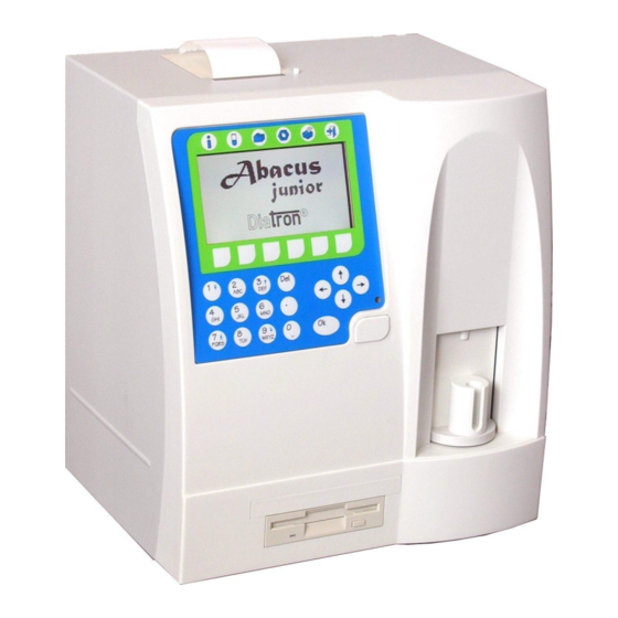
Introduction 1.3 Instrument features Abacus Junior Vet Figures 1 and 2 show a front and a back view of hematology analyzer. Figure 1. Front view Floppy disk drive OK key Numerical keypad Function keys Graphic liquid crystal display HELP key... - Page 10 Introduction Figure 2. Rear view 1. Reagent tubing connections 2. On/Off switch 3. External power supply inlet 12VDC 4. PS2 external keyboard port 5. USB port (not available yet) 6. Serial (RS 232) port #1 7. Parallel printer port...
- Page 11 Introduction Figure 3 shows an open built-in printer using roll paper inside. To open the lid, press the black button. Just put in the thermal printer paper and close the lid so that the end of the paper should be clipped between the black paper guide and the printer mechanics.
-
Page 12: Parts Of The Analyzer
Introduction 1.4 Parts of the Analyzer Abacus Junior Vet hematology analyzer is composed of three main units: Fluidic System: Performs sampling, diluting, mixing, and lysing functions. Generates the regulated vacuum used for moving cells through the aperture during the counting process. -
Page 13: Control Panels
Introduction 1.4.2 Control Panels START button Pressing and releasing the START button triggers an analysis cycle. Status indicator A three-color LED is located near the START button. Its actual color indicates the status of the analyzer. LED color Analyzer status The analyzer is ready to work. - Page 14 Introduction Function keys Below you can find all the possible icons and functions assigned to the so-called soft- keys (function keys) Function Action triggered Exit from actual menu or action Leave data-entry menu without saving any changes made to it (Cancel) Confirm the results or changes made (OK) Display histograms of the highlighted patient ID or QC Lot No.
-
Page 15: Control Material
1.6 Accessories Abacus Junior Vet Below is a list of accessories shipped with your instrument. Abacus Junior Vet This list can also be referred as the “DIATRON - pack” Abacus Junior Vet Hematology Analyzer Abacus Junior Vet User's Manual (this booklet) -
Page 16: Specifications
Introduction 1.7 Specifications 25 µl whole blood (50 µl in Prediluted mode) Sample volume: 80 µm (in one universal measuring chamber) Aperture diameter: Throughput: approximately 30 tests/hour Accuracy Reproducibility Carry over Test range Characteristics: max deviance between from expected samples (CV) 4.0 –... -
Page 18: Installation
2.2.1 Electrical requirements Abacus Junior Vet comes with a power cord appropriate for your power system. Proper use of the appropriate power cord assures adequate grounding of the system. Abacus Junior Vet... -
Page 19: Space Requirements
DO NOT PLACE the reagents above the instrument, as there can be a risk of falling and spilling. WARNING: Install the unit on a table or workbench. If the unit is installed without a supporting desktop under the unit, there is a possibility that the Abacus Junior Vet could accidentally fall. 2.2.3 Peripherals External peripherals should only be connected when both the instrument and the peripheral device are powered off. -
Page 20: Maintenance
Installation 2.2.5 Maintenance The user should check the following components weekly: bottom of washing head for salt build up – should be wiped off with a damp cloth tubing system – by opening the side and back doors and look for any liquid leakage. -
Page 21: Unpacking And Installation
Installation 2.3 Unpacking and installation Abacus Junior Vet 1. Carefully remove the hematology analyzer from the shipping carton. Inspect the instrument for any visible signs of damage incurred during shipping. If you find any damage, immediately file a claim with the carrier or your distributor. - Page 22 Place the reagent containers near the instrument, to an accessible location. Do not place the containers to a higher position than that of Abacus Junior Vet , because would a tube come off its connector, the fluids spoil out. Use the supplied connecting tubes and special bottle caps.
-
Page 23: Turning The Instrument On
Installation 2.3.1 Turning the Instrument ON a. In case you use an external printer (for information, read manual shipped with the printer) connect it and turn it on. b. Turn on the instrument by flipping the power switch (above the external power inlet) to I position. -
Page 24: Turning The Instrument Off
Installation 2.3.2 Turning the Instrument OFF The instrument should never be switched off by simply pressing the power button on the rear panel. Doing so may result in erroneous operation during later use. It can be so, because the instrument uses different kinds of solutions, one of which is the so- called diluent. -
Page 25: Preparing For Shipment
Installation 2.3.3 Preparing for shipment The second item in the shut down menu should be used when the instrument is to be shipped or left unused for a longer time. The instrument will ask you to utilize the cleaning tube kit and 100ml of distilled water. Follow the instructions appearing on the display. -
Page 26: Menu System
Menu system 3 MENU SYSTEM 3.1 General Information This chapter contains information about the structure and usage of the software implemented menu structure. This integrated software controls instrument operations including calculation and evaluation of measured data, displaying results and information screens storage and recalling of data. - Page 27 Menu system arrow The arrow under the Printing short cut-key indicates Printing function is enabled. b. You can select the desired item with the keys and press the OK key to enter or activate the highlighted item. Within a submenu, you can press the function key to return to the previous menu level.
-
Page 28: Menu Structure
Menu system 3.1.2 Menu Structure Measure local F1 Repeat last sample Measure blank Select by date time, and ID Predil mode Select all WBC only Deselect all Needle Height Setting Unsorted Database local F1 Go to specified record Sort by time Selection Sort by sample ID Change sort order... -
Page 30: Operating Principles
Operating prinicples 4 OPERATING PRINCIPLES 4.1 Impedance Method The impedance method (a.k.a. Coulter method) counts and sizes cells by detecting and measuring changes in electrical impedance when a particle in a conductive liquid passes through a small aperture. Internal electrode Aperture Blood cell suspension External electrode... -
Page 31: Parameters
Operating principles 4.3 Parameters Abacus Junior Vet measures and calculates 18 different parameters, listed below. For each parameter you can find the name, the abbreviation and the measurement unit in the first column. You can find a short description for each parameter in the second column. -
Page 32: Absolute And Linearity Ranges Of Measured Parameters
Operating prinicples 4.4 Absolute and Linearity Ranges of Measured Parameters Within the linearity range, the instrument is guaranteed to provide the specified accuracy. Beyond this linearity range, the instrument is able to display results, but may not guarantee accuracy characteristics. If the value is over the maximum range of guaranteed linearity, the instrument cannot measure it and the result will be marked with an E (Error) flag. -
Page 34: Routine Utilization And Measure
Routine utilization 5 ROUTINE UTILIZATION and MEASURE 5.1 Sample handling Since some time will usually elapse between collection of samples and counting, it is necessary to preserve the sample with an anti-coagulant to prevent large groups of cells forming into clots or lumps of cell matter that will clog the cell counter. Choice of anti-coagulant is very important, as some anticoagulants will affect the shape and size of blood cells. - Page 35 Routine utilization To initiate analysis: 1. Invert the closed sample tube 11 times to achieve a homogenous sample. Do not shake the sample, because micro-bubbles can form inside causing erroneous sampling! You have the possibility to use 3 different interchangeable adapters for different tube types.
- Page 36 Routine utilization 2 ml control blood Figure 10. Tube used in small adapter 2. Remove the cap!! It is very important because the tip will not pierce the cap! 3. Position the sample tube in the sample rotor. 4. Push START key. The sample rotor will turn into inside of the instrument and the needle draws 25μl of sample from the tube.
-
Page 37: Sample Analysis
The two important parameters influencing lysing are lysing time and lyse quantity. You cannot change the lysing time, as it is adjusted to the lysing reagent supplied by Diatron. Above you could read that the lyse quantity can be adjusted either at patient limits, or... -
Page 38: Sample Information
Routine utilization 5.2.3 Sample information The software allows the user to enter information for each sample that has been, or will be, measured. If an external PC keyboard (standard USA layout) is used, it must be connected to the instrument before turning the instrument on. Two options exist for sample information entry: immediately before analysis in the Database menu... - Page 39 Routine utilization In the followings we summarize the warning flags and give an explanation of their possible cause and a few hints to overcome the problem: Uppercase letters refer to WBC or HGB problems: Flag Meaning Recommended user action No WBC 3-part differential Possible lyse problem.
-
Page 40: Measure
Routine utilization 5.3 Measure Pressing the MEASURE short-cut key the measurement screen is displayed. The default measurement screen is set to Human species. From here you can reach the Profile screen by pressing the button. The Profile icon allows you to choose between different species. -
Page 41: Measure Local Menu
Routine utilization 5.3.1 Measure local menu From the Measure local menu you can access 4 sub-menus. 5.3.1.1 Repeat last measurement Choosing item 1 from the Measure local menu the last measurement can be repeated and an R sign will be displayed on the upper left corner of the screen. -
Page 42: Prediluted Mode
Routine utilization There are 3 regions for blank value handling: 1. Optimal - all results are within acceptable ranges. 2. Blank is high - * flag is displayed at relevant results. 3. Blank exceeds acceptability - no results displayed. Parameter 1. No flag at parameter 2. -
Page 43: Wbc Only
Routine utilization NOTE: The Prediluted mode has its own calibration factors. To calibrate the instrument for this mode, see the Calibration settings section of this manual. To disable the Prediluted mode, re-enter Measure local menu and deselect its box. 5.3.1.4 WBC only Selecting item 4 in Measure local menu the instrument will measure and display WBC parameters only. - Page 44 Routine utilization Another icon allows changing between markers, and you can also reset the markers to original (calculated) or to previous states (x). You can accept the modifications with the (check). If any marker was moved, the respective parameters become underlined.
-
Page 46: Database
Database 6 DATABASE Patient results are stored in the memory in chronological order, and can be retrieved at any time. Memorizing capacity is 1,000 measurements, including the complete parameter list, histograms, flags, sample data, and date/time of measurements. DATABASE Pressing the key accesses the remaining, non-visible parameter results. - Page 47 Database <DATABASE LOCAL MENU> SELECTION (2) Besides checking samples one-by-one, selection can also be done within Database local menu. SELECT ALL checks all boxes, DESELECT ALL clears all boxes. <DATABASE LOCAL MENU> SELECTION (2) SELECT BY DATE, TIME AND ID Select a range by date, time and/or ID number (see next screen) Entering 0 as an ID results in a search by date...
- Page 48 Database When you have selected the day or data to ! Message 5104/12210 be saved, and confirmed it with the 35 data record(s) will be saved on 1 disk(s). key, the instrument will prompt you for an Insert an empty floppy disk! empty disk.
-
Page 50: Utilities
Utilities 7 UTILITIES 7.1 Maintenance By selecting item (1) of the UTILITIES you can access the MAINTENANCE menu. 7.1.1 Regular Maintenance Jobs From Maintenance submenu, the user can initiate maintenance procedures such as cleaning, priming, draining. MAINTENANCE (1) Select the required submenu. 7.1.1.1 Cleaning Item 1 in the above menu brings up cleaning functions. -
Page 51: Priming
Utilities 7.1.1.2 Priming During the priming cycle, the fluidic system is rinsed with a large amount of diluent. It differs from the process in a start-up procedure; as in the latter case a simple filling up of the fluidics is performed. If fluid sensors are on, then the analyzer makes these procedures automatically, otherwise the User must initiate them activating the appropriate item within... -
Page 52: Weekly Maintenance
Utilites WASTE HANDLING – VERY IMPORTANT Waste contains poisonous substances (because of possible cyanide content) and human origin substances causing biohazard. These substances are representing potential danger to environment. For this reason, safe handling of the waste liquid is very important. Please contact your distributor which kind of reagent is supplied to you, whether the lyse reagent contains cyanide or it is cyanide-free. - Page 53 Utilities to close the doors turn the lock counter clockwise until the door is blocked Needle moving mechanics Washing head Micro dilutor Chamber and aperture Amplifier assembly Sample rotor Reagent tubing connections Valve block Figure 11. Reagent Internal sensors printer Valve block Diluent and Lyse Dilutor...
-
Page 54: Cleaning The Washing Head
Utilites 7.1.2.1 Cleaning the washing head The washing head cleans the outer surface of the aspirating tip with saline diluent. Any salt build-up on the lower surface may cause malfunction during operation. Use warm tap water and a soft cloth to clean this area. You can see the washing head indicated in the following figure: Washing head Measuring... -
Page 55: Calibration
Utilities Now you can pull the plastic holders off the tube. Retain all parts except the old tube. Put the tube back into the pump mechanics, and drive the grey plastic parts into their seats as figure 2 indicates. (view from the “top” of the pump) Slide the cassette housing back. - Page 56 Utilites CAUTION! New calibration will invalidate the previous factors. Old values cannot be retrieved, but can be reviewed in the VIEW CALIBRATIONS menu. Calibration can be initiated by choosing Calibration in the UTILITIES. Item 1 opens the CALIBRATE menu level, which is displayed in the following screen.
-
Page 57: Factorial Calibration
Utilities 7.2.1 Factorial calibration If the CALIBRATION MODE has been previously set to Factorial Calibration, the factors can be set manually in the 0.80 - 1.20 range. UTILITIES CALIBRATION (2) CALIBRATE (1) (factorial) Enter previously calculated factors using the numerical keys; confirm with the OK key. 7.2.2 Automatic calibration by measurement If the CALIBRATION MODE is set to one- or three-fold measurements, calibration measurements are performed with a hematology control substance. -
Page 58: View Calibrations
Utilites After entering the required reference values, perform analyses on the control material. Press to accept results. number calibration analyses performed is shown on the first line. Following calibration, the new factors are Calibration displayed. The previously used factors are 1.02 (1.03) shown in parentheses for reference. -
Page 59: Quality Control
QC levels. Abacus Junior Vet provides six different Quality Control levels. You can set up six individual reference sheets for each control material (e.g. low, normal and high control blood). -
Page 60: Qc Database
Utilites UTILITIES QUALITY CONTROL (3) SET QC REFERENCE (1) Both target values and acceptable ranges can be specified. Only the parameters displayed these screens utilized. Modify displayed values using numerical keyboard. Pressing the OK key accepts data. Use the page down function key to view additional parameters. -
Page 61: Diagnostics
Utilities CAUTION! Any change in the QC material settings is followed by deletion of the QC database. It is strongly recommended to print the database before making modifications. The analyzer produces graphic figures of the QC measurements. UTILITIES QUALITY CONTROL (3) VIEW QC DIAGRAM (4) Means, standard deviations (StDev) and coefficients... -
Page 62: Device Statistics
Utilites 7.4.1 Device statistics UTILITIES DIAGNOSTICS (4) STATISTICS (2) This menu includes important information about analyses previously performed: the total number and any clogging or errors incurred. 7.4.2 Self test The Self test is a procedure to verify proper operation of essential components of the instrument. -
Page 63: Settings
Utilities 7.5 Settings Selecting item four (4) of the UTILITIES you can access this menu. The SETTINGS sub-menu allows the user to set the fluid detector operation, printing parameters, dates, user modes and various data. 7.5.1 Printer Settings Make sure to select the appropriate printer mode for correct operation before printing. The instrument supports the following printer modes and languages: Selected mode Printer language... - Page 64 Utilites Any printer compatible with the above listed modes (printer languages) can be connected to the instrument. To set up the instrument for your printer, go to the “Utilities/Printer/Printer Settings” menu. Select from the options using the up and down arrow keys within the text fields, and fill in the numerical fields using the number keys.
- Page 65 Utilities Narrow full Full with histograms, ½ page Table format defines how a table-printout will look like. You can select normal or narrow view. A normal table is as wide as the paper, narrow format has parameters grouped such, that Printer cable defines which communication is to be used between instrument and printer.
- Page 66 Utilites One result per page – if enabled – starts each printout on a separate sheet, if disabled then it will print as many recoeds on a page as possible (small printout size combined with disabled “One result per page” may give e.g. 3 small reports on one sheet.) Rollpaper ON will disable starting a new page at end of each record.
- Page 67 Utilities Rollpaper: No (especially for LaserJets) Printout format: Full with histogram or Wide text only One result per page: Use “No” to save paper 7-18...
-
Page 68: Troubleshooting Guide For Printing Problems
Utilites 7.5.1.1 Troubleshooting guide for printing problems Problem Possible reasons/remedies Printer does not respond, Printer is off. Turn it on. no printout. Printer is not connected to analyzer. Connect it to the parallel or USB port of analyzer. Printer is not on-line. Switch it to on-line mode. Printer is out of paper. -
Page 69: Customize
Utilities 7.5.2 Customize SETTINGS (5) CUSTOMIZE (2) This is a collection of settings influencing instrument operation, customization. 7.5.2.1 General settings SETTINGS (5) CUSTOMIZE (2) GENERAL SETTINGS (1) This is a collection of settings influencing instrument operation, customization. Enable Sound: Selecting NO will disable all system sounds. Language: list of available languages Serial I/O speed: select any other setting other than offline to enable serial communication... -
Page 70: Units
Move between character places using the keys. 7.5.2.4 User modes Selecting item six (6) of the Settings menu you access this menu, where you can Abacus Junior Vet enable Multi-user Mode of 7-21... -
Page 71: Multi-User Mode
The multi-user mode allows identification of operators through their personal settings, or profiles. It also restricts users to certain software functions. Abacus Junior Vet , the term „multi-user‟ means storing profiles for different users, but does not mean allowing more than one user being logged in simultaneously. - Page 72 Utilites USERS MODES (6) ADD NEW USER (3) The software assigns an individual ID to each new user. In the name field, a user name of 32 characters can be specified. You can use either the keypad, or the external PC-keyboard. When the name is entered, the level should be defined as Supervisor, Advanced or Basic.
-
Page 73: Date And Time
Utilities 7.5.3 Date and Time The date and time of each analysis is stored with the results. This menu allows setting the built-in clock and the format of the date displayed. SETTINGS (5) DATE AND TIME (2) By selecting item 1, you will enter date and time setting mode (next screen). -
Page 74: Printing
Printing 8 PRINTING This chapter covers information on making reports on measured samples. This chapter covers information on making reports on measured samples. 8.1 Printouts When required, the following items can be sent to an external printer or to a built-in printer by pressing the function key button. - Page 75 Printing Full printout formats with histograms: Header Patient info Sample and measurement info Limits, or graphical location of the result within the range of limits Histograms Location of warning flags (not displayed now)
- Page 76 Printing Figure 16. Built-in printer printout In the left side printout the reference ranges (limits) are in normal mode (indicated by numbers) while in the right side printout the reference ranges (limits) are in graphical mode, flags and warning flags are not enabled. The printing modes of these parameters can be selected within PRINTER SETTINGS submenu.
-
Page 78: Fluidic Schematics
Fluidic Schematics 9 Fluidic Schematics... - Page 79 Revision history: Revision Section Modification Menu system I. Losonczi 2003.07.10 1.21 Needle setting possibility I. Losonczi 2003.09.16. 1.21 2.3.4 Emergency handling I. Losonczi 2003.09.16. 1.21 7.1.5 Waste handling I. Losonczi 2003.09.16. 1.21 Use of rubber gloves I. Losonczi 2003.09.16. 1.21 5.3.1 New sub-menu: WBC only I.
Need help?
Do you have a question about the Abacus Junior Vet and is the answer not in the manual?
Questions and answers