
Summary of Contents for PROLEC Liftwatch 5
- Page 1 Part Number 560361-020 Issue 1.0 November 2012. Liftwatch 5 Rated Capacity Indicator Operator Manual...
- Page 3 Any alterations or modifications to machine components which affect this system and any system component failure must be reported to Prolec Ltd or via the machine convertor/service agreement holder. This manual must be kept with the product and be passed on to any subsequent user of the product.
-
Page 4: Table Of Contents
Contents Power up Operation - general Operation - overload Operation - motion control Operation - override Operation - low pressure System test Load charts... -
Page 5: Power Up
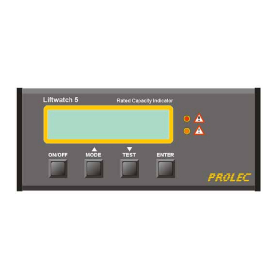
The Liftwatch 5 Rated Capacity Indicator can be configured during installation to operate in one of two ways. Automatic If the auto-on link has been fitted to the display PCB, Liftwatch 5 will automatically power up when the machine ignition is switched on. Manual If the LCD display remains blank after the machine ignition is switched on, press the ON/OFF button once (circled in red below). - Page 6 Part Number 560361-020 Issue 1.0 November 2012. Power up (continued) ANG1 no response : ANG2 no response : COMB no response : This message indicates the combined This message indicates the arm angle This message indicates the combined boom angle and dual pressure CAN bus sensor is not operating input/output CAN bus controller is not transducer CAN bus sensor is not...
-
Page 7: Operation - General
Part Number 560361-020 Issue 1.0 November 2012. Operation - general SWL* Radius Maximum safe working load in tonnes for the active lifting duty. The Distance in metres from the slew load is assumed to be suspended vertically below the lifting point. centre line to the lifting point. -
Page 8: Operation - Overload
Part Number 560361-020 Issue 1.0 November 2012. Operation - overload Approach to maximum safe working load When the suspended load constitutes more than 95% of the maximum permissible safe working load the amber LED will illuminate and the internal alarm will sound. When the suspended load exceeds the maximum permissible safe working load by more than 5% the red LED will illuminate, the internal and external alarms will sound, and all equipment motions that would decrease the SWL further will be disabled. -
Page 9: Operation - Motion Control
Part Number 560361-020 Issue 1.0 November 2012. Operation - motion control A green arrow indicates that the SWL will be increased if that section of the equipment is moved in the direction of the arrow An amber arrow indicates that the SWL will decrease (as the radius increases) if the equipment is moved in that direction. A red arrow indicates that the load will be RAISED if the equipment is moved in that direction. -
Page 10: Operation - Override
Part Number 560361-020 Issue 1.0 November 2012. Operation - override When the system is in a overload condition certain equipment motions will be disabled. Condition No 4 shown on the previous page has all motions disabled. To allow the machine to be moved to a safe position the motion control can be cancelled. To override the system press the MODE button. -
Page 11: System Test
Press TEST to access this feature. Press Equipment lengths can only be altered by Prolec or their appointed agents. TEST again to scroll through the available displays. - Page 12 Part Number 560361-020 Issue 1.0 November 2012. System test (continued) When this display is shown the display red LED should operate. Pressure is shown in bars. The pressure should increase with additional load, or increased load radius. Pressure should fall to zero when the equipment rests on the ground.
-
Page 13: Load Charts
Load charts Each Liftwatch 5 system will have one or more load charts similar to the EXAMPLE above. Maximum safe working loads are given in tonnes at suitable height and radius increments. Radius is given in metres and is the distance from the slew centre line to the lifting tool pin. - Page 14 Part Number 560361-020 Issue 1.0 November 2012. Prolec Ltd 25 Benson Road Nuffield Industrial Estate Poole England BH17 0GB Tel: +44 (0)1202 681190 E-mail: service@prolec.co.uk...
Need help?
Do you have a question about the Liftwatch 5 and is the answer not in the manual?
Questions and answers