
Summary of Contents for Uniflair UTS01
- Page 1 UNIFLAIR Instruction manual UTS01 TOUCH SCREEN TERMINAL FOR CLOSE CONTROL UNITS...
- Page 2 Close Control Regulation Program UNIFLAIR SpA policy is one of continuous technological innovation. The Company therefore reserves the right to amend any data herein without prior notice. Disposal: the product is made up of metal parts and plastic parts. In reference to European Union directive 2002/96/EC issued on 27 January 2003 and the related national legislation, please note that: •...
-
Page 3: Table Of Contents
CO: ASSIGNING THE LIST OF PRIVATE AND SHARED TERMINALS ................. 9 “GENERAL OPTIONS” MENU ..............................9 UPDATE THE FIRMWARE ............................... 10 SIGNALS ....................................11 TECHNICAL SPECIFICATIONS ............................... 11 POWER SUPPLY CONNECTIONS TO THE UTS01 ......................... 12 SERIAL INTERFACE LAN ..............................12 FUNCTIONAL CHARACTERISTICS ............................12 GENERAL CHARACTERISTICS .............................. 12 DISPOSAL OF THE PRODUCT .............................. - Page 4 Close Control Regulation Program MAIN SETTINGS ..................................36 MEMORY OPERATIONS ................................. 39 ALARM RESET MODE ................................39 SENSOR ADJUSTMENT ................................40 SOFTWARE SETTINGS ................................40 HARDWARE SETTINGS ................................45 COMMUTATION OF PRIVATE TERMINAL UST01 TO UG40 ....................50 ALARMS ....................................... 51 ACTIVE ALARMS ..................................
-
Page 5: General Features
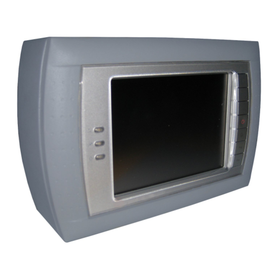
Close Control Regulation Program GENERAL FEATURES The UTS01 is an electronic device designed as the user interface for the UpCO range of controls The UTS01 is a 256-colour LCD graphic terminal with 320x240 pixel resolution and CCFL backlighting. PANEL INSTALLATION These terminals have been designed for panel installation;... -
Page 6: Installation And Mounting
Fig. 2 CONFIGURATION The UTS01 is configured by the manufacturer for the more common user requirements. Nonetheless, some settings can be changed, so as to adapt the device to specific needs. The menus can be accessed by pressing any point on the touch-screen together with the (up) and Prg buttons for at least one second. -
Page 7: Description Of The Display Menu
Close Control Regulation Program To access an item, simply press the touch-screen on the corresponding indication, or press the (up) / (down) buttons until selecting it and then confirm by pressing (enter). To modify the value of a field, after having activated it (a field is active when the cursor is flashing inside), press the (up) / (down) buttons to change the value and press (enter) to save it. -
Page 8: Network Configuration" Menù
Close Control Regulation Program “NETWORK CONFIGURATION” MENÙ Fig. 7 The following options are possible: • • • • Terminal Address: Used to set the address of the terminal (from 1 to 32, default: 32). If the value “--” is set (two dashes are displayed) the terminal will communicate with the UpCO board using the “Point-Point”... -
Page 9: Upco: Assigning The List Of Private And Shared Terminals
Important: the UTS01 terminals cannot be configured as “Sp” (shared printer) as the printer output is not featured. Selecting this mode has no effect on the management of printed messages sent via pLAN. -
Page 10: Update The Firmware
UPDATE THE FIRMWARE The firmware of the UTS01 terminal can be updated when new versions become available, using the “Display Firmware Update” function, accessible from the “General Options” menu. The updates must have previously been loaded onto a UpCO connected in the pLAN network, following the instructions provided with the documents on the UpCO application development tools. -
Page 11: Signals
Close Control Regulation Program Fig. 13 At the end of the download, the user will need to confirm the update, see Fig. 14. Fig. 14 Pressing “No” will cancel the operation. Pressing “Yes” starts the programming procedure. At the end of the programming procedure, which takes around one minute, the “Successful” message will be displayed for a few seconds, indicating that the operation was completed correctly. -
Page 12: Power Supply Connections To The Uts01
POWER SUPPLY CONNECTIONS TO THE UTS01 Observe the following rules: • The power supply terminals on the UTS01 are called G and G0. The connection is made using 2-pin removable terminals. Possible cross-section of the wires: 0.5 to 1.5 mm ; •... -
Page 13: Plan Network Connection
Case “B” In this diagram a pLan connection is shown between units with their own private UTS01 local user terminal and a shared UTS01 remote user terminal. Connection to the private UTS01 terminal is made through a J11 terminal of the board of each unit, making sure that the indicated polarities are respected. - Page 14 In this diagram a pLan connection is shown between units with their own private UG40 local user terminal, a private UTS01 remote user terminal and a shared UTS01 remote user terminal. Connection to the private UG40 terminal is made through the J10 telephone terminal while connection to the private and shared UTS01 terminal is made through J11 board terminal, used as a connector to the pLAN network respecting the polarities marked.
- Page 15 TERMINAL DISABLED: TOUCH SCREEN USER TERMINAL IN USE Commutation from UTS01 to UG40 In order to activate functioning, communication must be switched from UST01 private terminal by following these simple steps: 1. Access the Service Menu after having entered the Password 2.
- Page 16 Close Control Regulation Program Commutation from UG40 to UTS01 1. Access the Service Menu after having entered the Password _HARDWARE SETTINGS _SOFTWARE SETTINGS _SENSOR ADJUSTMENT _ALARM RESET MODE _MEMORY OPERATION _MANUAL CONTROL _UG40-->UST01 touch s. 2. Select the line UG40-->UST01 touch s.
- Page 17 Close Control Regulation Program To configure the UTS01 terminals, 1. Disconnect the pLan network through the back terminal 2. Press UP+ENTER+DOWN until this screen is displayed. 3. Modify the address TERMINAL ADDRESS according to which unit must be monitored. Example: unit 1 = address 21 4.
- Page 18 Close Control Regulation Program CABLE FOR LAN AND SUPERVISION CONNECTION For connection to both LAN and supervision networks, it is advisable to use a cable which has the following specifications: Multi-coupled cables with internal flexible conductors made from tin plated copper (AWG 22/7), insulated with polypropylene, singularly coupled, screened with aluminium/polyester tape + continuity wire in tin plated copper (AWG 24/7) connected on a common axis to reduce the diameter and protected by an external sheath in PVC.
-
Page 19: Unit Start Up Conditions
Close Control Regulation Program UNIT START UP CONDITIONS The following operations must be performed before the user can start the unit: • check that the light on the display is on (controller powered); • check that the red light on the button is off (no alarms active);... -
Page 20: Password
Close Control Regulation Program PASSWORD To switch on the unit in programming mode (READING AND WRITING) in the SETTINGS and SERVICE MENUS, a password must be inserted which can be found in an envelope attached to this manual which is addressed to the maintenance staff. -
Page 21: Variation Of Parameters
Close Control Regulation Program VARIATION OF PARAMETERS Modification of set parameters and/or configuration in a subroutine (set point, differential…), is as follows: 1. proceed to screens in the programming method; 2. select with the buttons the screen that shows the parameter; the cursor ( _) flashes in the top left corner;... -
Page 22: Icons When The Unit Is Switched Off
Close Control Regulation Program ICONS WHEN THE UNIT IS SWITCHED OFF When the unit is switched off, the following icons appear in field D indicating the unit status or any action which needs to be taken: press the button to switch on the unit the unit is switched off by remote On/Off contact the unit is switched off by a supervision system the On/Off cycle is activated with timing program... -
Page 23: Description Of Keys
INTEGRATED KEYBOARD The UTS01 terminal features an integrated keyboard on the right hand side of the display and is also available with a touch screen display where the image of the operation desired is touched in order to activate it. -
Page 24: Graphic Keyboard
Close Control Regulation Program The LED signals on the left hand side of the display are as follows: A red flashing led indicates as active alarm; A green led indicates the display is powered A green led indicates the unit is switched on GRAPHIC KEYBOARD HELP button: by pressing this button a brief description of the different buttons which can be touched appears (see the diagram below for an example). -
Page 25: Status Menu Description
Close Control Regulation Program STATUS MENU DESCRIPTION This part of the program allows the information regarding unit operation to be displayed; only information and data appear relative to the configuration chosen. Icons indicating their use appear on the main screen. To access them, touch the icon desired on the display and the operation will appear in read only without having to insert a password. -
Page 26: Alarms History
Close Control Regulation Program ALARMS HISTORY This screen and the following display the historical sequence of the alarms activated; the microprocessor stores the last 100 events in its memory. All the alarms saved can be read in sequence by pressing the UP or DOWN button;... -
Page 27: Input/Output
Close Control Regulation Program The buttons below the display are as follows: • Activates the buttons for the Panoramic mode • Displays the data with the lowest available index • Scroll towards the left • Scroll towards the right • Scroll upwards •... -
Page 28: Humidifier Status
Close Control Regulation Program HUMIDIFIER STATUS This screen and the following one display the information from the humidifier board. LAN NETWORK CONNECTION STATUS This screen allows the information from the LAN Network to be displayed. From here it is possible to select the required unit by simply touching the image on the display. -
Page 29: Description Settings Menu
Close Control Regulation Program DESCRIPTION SETTINGS MENU This part of the program allows the unit operations to be calibrated. To access the menu follow the instructions described in the PASSWORD section of this manual. LAN SETTINGS For units with UpCO control, the microprocessor is enabled for the automatic management of a local network connected to more than one unit (up to a maximum of ten), of which some are in operation and others are in stand-by (up to a maximum of two units). -
Page 30: Operative Settings
Close Control Regulation Program OPERATIVE SETTINGS SETPOINT All variables are pre-set in the factory so that the control functions correctly, maintaining standard conditions in the room. This screen shows and allows you to set: • the probe used for temperature control; •... - Page 31 Close Control Regulation Program COMPENSATION SETPOINT This screen allows compensation control to be activated and set when a discharge air sensor is used for checking the ambient temperature. Depending on the return temperature (Room Temp.) detected, the control sets a setpoint (Delivery Setp.) from those set in point 1 or point 2.
-
Page 32: Alarm Relay Selection
Close Control Regulation Program ALARM RELAY SELECTION This screen is used to change the status of the alarm signal contact, type “A” and “B”. This screen and the following are used to determine the digital output that signals the alarm. The configuration of an alarm does not affect the action performed by the controller (signal only on the display or shutdown of the device affected by the alarm). -
Page 33: Clock Settings
Close Control Regulation Program CLOCK SETTINGS If the microprocessor is fitted with the optional clock circuit the date, time and weekday is shown in the STATUS screen. The following are possible by using the clock settings: • start up and shut down of the unit according to a timed program; •... -
Page 34: Serial Comunication
Close Control Regulation Program EVACUATING THE HUMIDIFIER CYLINDER The steam cylinder needs to be periodically cleaned from limescale deposits; before removing the cylinder for replacement or cleaning it is necessary to completely drain all of the water from the boiler. To carry out this operation it is necessary to access the screens and scroll through them until the correct screen is shown: •... -
Page 35: Service Menu Description
Close Control Regulation Program SERVICE MENU DESCRIPTION This part of the program is used to configure the devices installed on the unit and their operation; these operations should be performed by qualified personnel. Note that the manual describes the functions of the program in general and that based on the configuration set, the fields and configuration screens may be enabled or disabled. -
Page 36: Eev Valve Settings
Close Control Regulation Program The next screen can also be used to set, as a percentage, the opening of the devices connected to analogue outputs Y1, Y2 and Y3. If the UpCOE is connected in the CW Dual version Coil, the setting of analogue output Y1 will also be displayed. - Page 37 Close Control Regulation Program This screen is used to set: Range Begin.: start scale for the evaporation pressure transducer reading; Range Ending: end scale for the evaporation pressure transducer reading; Read Value: the value read, i.e. the measurement sent by the probe. This screen, allows the reading of the pressure evaporating sensor to be corrected if a difference between the measured value of the sensor and the effective value is detected when measured with a...
- Page 38 Close Control Regulation Program This screen is used to manually set the opening steps for the electronic expansion valve. This screen is used to set the opening steps for the electronic expansion valve when there is no cooling request. ADVANCED SETTINGS This screen is used to set: Superheat Set: superheat set point;...
-
Page 39: Memory Operations
Close Control Regulation Program This screen is used to set: Dehum.SH Set: superheat set point in the dehumidification phase; LOP Limit: minimum operating pressure limit in the dehumidification phase. MEMORY OPERATIONS This screen manages the data contained in the microprocessor Flash EPROM. -
Page 40: Sensor Adjustment
Close Control Regulation Program SENSOR ADJUSTMENT This screen and the following one allow the reading of the temperature sensors ("ROOM TEMP.", "EXT. AIR TEMP.", "DELIVERY TEMP.", "CHILLED WATER CLOSED and HOT WATER", "ROOM HUMIDITY") to be corrected if a difference between the measured value of the sensor and the effective value is detected when measured with a precision instrument. - Page 41 Close Control Regulation Program These screens are used to establish the settings for the condensing circuit: on direct expansion units; on twin cool or Energy Saving units, during the mechanical cooling phase (with only the compressors on). The controller keeps the water temperature in the closed circuit at a suitable value for condensation, between the set point and the set point + a fixed differential of 6°C.
- Page 42 Close Control Regulation Program This screen is only available in the Twin-cool version and is used to enable CW operation • if the alarm is activated in DX mode; • only via multifunction digital contact; • only by BMS. This screen is used to set the type of control in Cooling Water mode: Room Temperature: the unit controls the return air temperature;...
- Page 43 Close Control Regulation Program This screen is only available in the CW Dual Coil version and is used to establish the operating parameters for the water valves in circuits 1 and 2. The default configuration is P1=100 % and P2= 0 %, that is, both valves open with the same control ramp.
- Page 44 Close Control Regulation Program This screen is used to set: T+H Al. Delay’: delay in signalling room alarms when starting the unit and in normal operation. Wrong Phases Sequence or Phase Loss: minimum unit OFF time if the alarm is activated. This screen is used to change the access passwords: - for the settings ("SETTINGS"...
-
Page 45: Hardware Settings
Close Control Regulation Program HARDWARE SETTINGS The unit regulation program, after having cleared the memory if necessary, needs to be “configured”, that is adapted to the unit in which it is installed; in this phase it is necessary to define all the elements of the unit and that the microprocessor must control. - Page 46 Close Control Regulation Program This screen is used to configure analogue input 6 as an outlet temperature sensor (Deliv.Temp.Sensor) or as a hot water sensor (Hot Water Sensor) or as an outlet water temperature sensor (Water Out Sensor). Only on units with UpCO1 Small controllers. This screen is used to configure digital input 5 as: No switch connected: no connection;...
- Page 47 Close Control Regulation Program If the digital input chosen is configured as USER CONFIGURATION, the following screen is used to select the other functions: Alarm signalling: alarm signal coming from a component outside of the unit; DX/CW Switch-Over: external digital contact for changing over operating mode of the unit (Twin Cool version only) Emergency Working: signal coming from a component outside of the unit.
- Page 48 Close Control Regulation Program This screen, available if the underfloor air pressure transducer (AFPS) is fitted, is used to define: Set point: reference pressure value to be maintained by modulating the fan speed; Dead Band: dead band control Regul. Band: proportional band control Integral Time: integral time Derivat.
- Page 49 Close Control Regulation Program This screen, displayed only when the mechanical expansion valve is fitted, is used to establish the activation of the low pressure alarm by the pressure switch connected to ID6, setting: Alarm Delay After Compr. ON: alarm BP activation delay time from compressor ON Alarm Delay Normal Working: alarm BP activation delay time during normal operation...
-
Page 50: Commutation Of Private Terminal Ust01 To Ug40
Close Control Regulation Program This screen is used to set: Backlight Time: time the display backlighting remains on. This time also coincides with the timeout for entering the password. Buzzer Type: enables operation of the buzzer. Time ON: time the buzzer remains on This screen is used to set the mains frequency, automatically or manually. -
Page 51: Alarms
Close Control Regulation Program ALARMS ACTIVE ALARMS By pressing this button or this icon the alarm will be silenced and a description of the alarm will be displayed. If the cause of the alarm has been eliminated, the last alarm message can be reset by pressing the button or this icon for several seconds;... -
Page 52: Exceeding Temperature Or Humidity Limits
Close Control Regulation Program EXCEEDING TEMPERATURE OR HUMIDITY LIMITS These are alarms which are activated when the thermo hygrometric limits which have been set are exceeded (see the Operating Parameters screen). Signal only. This can be delayed during the unit start-up phase (the default delay is 15 minutes) Signal only. -
Page 53: Optional Sensor Or Digital Input Alarms
Close Control Regulation Program OPTIONAL SENSOR OR DIGITAL INPUT ALARMS These alarms are connected to the optional sensors and/or the configurable digital inputs (see the Hardware Settings screen). Signal only. (For Leonardo Evolution units and Amico CW units) Activated by the Smoke / Fire sensors and always causes the unit to switch off. -
Page 54: Unit Function Alarms
Close Control Regulation Program UNIT FUNCTION ALARMS These are alarms connected to the unit components and which are caused by the intervention of a protection device. Fan alarm: Activated by the differential air flow pressure switch (FS). Causes all of the devices to switch off (compressors, electrical heaters, humidifier, fans). - Page 55 Close Control Regulation Program CW units only (signal only). Activated by the chilled water temperature sensor when the set point value is not reached within 15 minutes of the dehumidification request. CW units only (signal only). Activated by the chilled water temperature sensor when the high temperature limit is exceeded.
-
Page 56: Afps Sensor Alarms
Close Control Regulation Program AFPS SENSOR ALARMS Alarms relating to the AFPS system. Active in the event of a fault on the under floor sensor, with the evaporator fan activated at maximum speed. Active when, after the threshold and the alarm activation delay time set have been exceeded, there is low under floor air pressure, with the evaporator fan activated at maximum speed. - Page 57 Close Control Regulation Program Activated following an error in the signal given by the NTC low pressure temperature sensor for the superheating reading. Also specifies the number of the circuit. Activated following an error in the EEPROM memory of the driver. Also specifies the number of the circuit.
-
Page 58: Humidifier Alarms
Close Control Regulation Program HUMIDIFIER ALARMS Active when the corresponding threshold is exceeded for more than an hour, or alternatively instantly when the conductivity of the supply water is three times higher than the corresponding high conductivity threshold. Disables operation of the humidifier. This may be shown in the following three cases: 1. -
Page 59: Sensor Alarms
Close Control Regulation Program Number of cylinder operating hours exceeded. Replace the cylinder This may be shown in the following two cases: Fill phase: if the maximum fill time has elapsed if the current measured does not reflect normal fill operation Pre-wash status: if during the fill phase the water level does not touch the high level electrodes within the maximum fill time... -
Page 60: Service Note
Close Control Regulation Program Disables the re-heat electric heaters Disables the hot water re-heat electric heaters (optional) Signal only Signal only Disables humidification / dehumidification operation SERVICE NOTE These are signalling alarms which are activated when the operating hours of the component are exceeded. This type of alarm, which continues until the counter is reset, is not however memorized in the historical alarm sequence. -
Page 61: Lan" Interupted Alarm
Close Control Regulation Program “LAN” INTERUPTED ALARM Indicates problems of communication between units in the LAN and specifies which units are not connected. This may be due to a break in the power supply, a malfunction in the serial card or an interruption in the electrical connections between the units. -
Page 62: Default Values
Close Control Regulation Program DEFAULT VALUES CONFIGURATION NUMERICAL PARAMETERS PARAMETER DESCRIPTION DEF. PARAMETER DESCRIPTION VAL. DEF. MIN. MAX. CONTROL PARAMETERS SET POINT Heating Cooling Set point Hot water coil with Room Temperature °C 23.0 17.0 35.0 Hot gas coil Cooling Propor. Band °C External Humidifier (On/Off) cooling set point... - Page 63 Close Control Regulation Program CONFIGURATION NUMERICALS PARAMETERS PARAMETER DESCRIPTION DEF. PARAMETER DESCRIPTION VAL. DEF. MIN. MAX. High Water Temp. (C1/C2) DELAY SETTINGS Low Air Pressure Integral Time 2000 AFPS: Expansion Board Anti-hunting time constant CW Dehumid. Failure (C1/C2) Unit Start Up Delay At Power On D.C.: Expansion Board Regulation Transient Supply Frequency...
- Page 64 Close Control Regulation Program CONFIGURATION NUMERICALS PARAMETERS PARAMETER DESCRIPTION DEF. PARAMETER DESCRIPTION VAL. DEF. MIN. MAX. Low Air Pressure Twin Cool SETTINGS AFPS: Expansion Board CW enable Setpoint °C 25.0 Room Temp.Sensor CW deactivation Setpoint °C Cooling Water SETTINGS Humidity Sensor Deliv.Temp.Sensor Dehumidification set point °C...
- Page 65 Close Control Regulation Program CONFIGURATION NUMERICALS PARMETERS PARAMETER DESCRIPTION DEF. PARAMETER DESCRIPTION VAL. DEF. MIN. MAX. SUPERVISION LOP Protection Integral Time 15.0 Serial Address LOP Protection Integral Time Auto Serial Speed (1200-19200) 1200 Dehumid. SH Set °C 20.0 40.0 Protocol Dehumid.
-
Page 66: Expansion Flash Memory
Close Control Regulation Program EXPANSION FLASH MEMORY GENERAL FEATURES The UpCO100CEF0 card is an option for the UpCO1 electronic controller that features, all on one card, a real time Clock, Eeprom memory and Flash memory: • the real time Clock manages the time, date (day, month, year) and includes buffer RAM for the software application (52 bytes);... -
Page 67: Upload File
UPLOAD APPLICATION In all 16-bit UpCO system controllers the resident software can be updated from a PC. To do this, UNIFLAIR Spa provides the WinLoad32.exe program and an RS485 serial converter for the UpCO. The special driver needs to be installed on the PC, again supplied by UNIFLAIR Spa. -
Page 68: Upload Pvt File
Close Control Regulation Program 8. click on the function key >>Done<<; UPLOAD PVT FILE The PVT file (Public Variable Table) defines which variables of the software application are public and therefore available to be logged in the event history. To load the PVT file follow steps 1 to 5 of the previous paragraph (Upload Application) then proceed as follows: 1. -
Page 69: Upload Lct File
Close Control Regulation Program 3. Click on the function key >>Done<<; UPLOAD LCT FILE The LCT file (Log Configuration Table) defines which of the variables, previously defined in the PVT file, are logged in the event history, therefore setting the principle characteristics of the archive, that is, defining if the sampling is to be carried out based on the event or on a time basis, in the latter case defining both the frequency and duration of sampling. -
Page 70: Download Logs File
Close Control Regulation Program 3. Click on the function key >>Done<<; DOWNLOAD LOGS FILE DOWNLOAD DA WINLOAD32 The selection “Log Data on Expansion Memory” allows the download of the data registration present in the appropriate expansion card of the Flash Memory to be carried out. To download the LOG Data file follow steps 1 to 5 of the previous paragraph (Upload Application) then proceed as follows: 1. - Page 71 Close Control Regulation Program 3. Click on >>Create NEW Log archive<< and create a new archive or overwrite an existing one by selecting the directory to memorize the file; Winload32, when the Download is complete, create 5 files inside the folder: •...
-
Page 72: Download From Smart Key
Close Control Regulation Program DOWNLOAD FROM SMART KEY Downloading of the LOGS files can also be carried out by a Smart Key. The Smart Key must, however, first of all be configured for reading by carrying out the following steps. Connect the Smart Key to the specific converter and start up the SMART KEY program, access the CONFIGURATION screen and select option “D : Read Logs ”. - Page 73 Close Control Regulation Program Once the directory has been chosen, highlight the file with the key’s contents and press the button to start downloading the file onto the hard disk and then press the button. At the end the following window will appear Once the download has finished, the Smart Key will generate 6 files within the folder: •...
-
Page 74: Notes
Close Control Regulation Program NOTES 06MC0071@00B0110 01/10/2012... - Page 75 Close Control Regulation Program 06MC0071@00B0110 01/10/2012...
- Page 76 Sede legale ed amministrativa Uniflair SpA Registered office & Viale della Tecnica, 2 Administrative Headquarters: 35026 Conselve (Pd) Italy Viale della Tecnica 2, Tel. +39 049 5388211 35026 Conselve (PD) Italy P.IVA 02160760282 Fax +39 049 5388212 C.C.I.A.A. di PD info@uniflair.com...
Need help?
Do you have a question about the UTS01 and is the answer not in the manual?
Questions and answers