Table of Contents
Advertisement
Quick Links
Advertisement
Table of Contents

Summary of Contents for Voice Solo XT VSM-300
- Page 1 User’s Manual VSM-300 Active Voice Monitor & Control...
- Page 3 IMPORTANT SAFETY INSTRUCTIONS The lightning flash with an arrowhead symbol within an The exclamation point within an equilateral triangle is equilateral triangle, is intended to alert the user to the intended to alert the user to the presence of important presence of uninsulated “dangerous voltage”...
- Page 4 These limits are designed to provide reasonable protection against harmful interference in residential installations. This equipment VoiceSolo VSM-300 generates, uses and can radiate radio frequency energy and, if not Active Voice Monitor and Control installed and used in accordance with the instructions, may cause harmful interference to radio communications.
-
Page 5: Table Of Contents
Specifications ....16 Audio path diagram ... .17 Specifications, interface, and features are subject to change without notice due to continued product improvement VoiceSolo VSM-300 Rev 1.01 English version... -
Page 6: Introduction
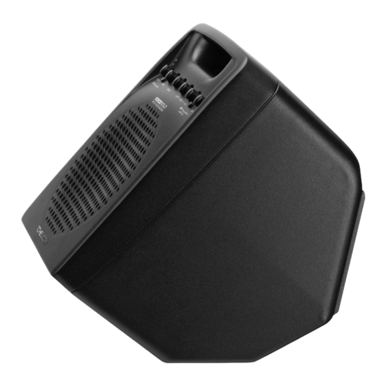
INTRODUCTION Welcome to VoiceSolo About TC-Helicon The TC-Helicon VoiceSolo VSM range of near field live monitoring speakers is a new concept in personal monitoring. TC-Helicon strives for excellence in all things related to vocals, and the VSM range builds upon the success and worldwide reputation of TC-Helicon's vocal expertise. - Page 7 Unpacking Open the box from the top and remove cabling and IO box (VSM-300 only). Lift out Styrofoam insert, then using both hands lift out VoiceSolo. Remove plastic bag from VoiceSolo. Nothing in your speakers should rattle. Inspect each speaker for signs of transit damage.
-
Page 8: Front Panel
FRONT PANEL 1. CLIP LED 5. LINE IN level control This LED is a sum of clipping from the MIC, LINE and AUX This sets the gain for the line input. Adjust this so that only inputs. the loudest notes you play light the CLIP LED. 2. -
Page 9: Back Panel
BACK PANEL 1. Phantom power button 4. LINE IN jack The Mic in has a phantom power switch that can be You may connect a mono line level signal through this jack pushed in to power condensor microphones. Otherwise this such as an acoustic guitar pickup, guitar multi-effect, mono should be left out. -
Page 10: I/O Box Diagram
EQ and LOW Connect the supplied DB15 cable here to connect the I/O CUT controls have no effect. The OUTPUT control sets the box with VoiceSolo VSM-300. master level. No Low Pass filter is applied on this output. -
Page 11: Mic Stand Mounting Procedure
MIC STAND MOUNTING VoiceSolo Placement Options 1. Separate the boom from the stand by unscrewing the boom from the vertical shaft of the microphone stand. To VoiceSolo can be placed in 4 different ways. This versatility do this, tighten the clutch you use to raise and lower the allows you to use it as a mic stand mounted monitor one stand first. - Page 12 MIC STAND MOUNTING 3. Place VoiceSolo on the mic stand so the stand goes 5. Screw the Mic Boom Mount Attachment into your boom. into the hole on the bottom of the VoiceSolo. If you don’t need to mount VoiceSolo on a boom stand, you are finished with your setup.
- Page 13 MIC STAND MOUNTING 7. Your VoiceSolo should now look like this. 2. Still holding the boom so that it does not swing away, turn the lock nut counter-clockwise until it’s snug against the bottom of the boom. Note that it’s not possible to completely tighten the lock nut with your fingers, the final action is done by swinging the boom snug against the lock nut.
-
Page 14: Making Connections
PA system from VoiceSolo. due to the high power to size ratio of BASH amplifiers. • It allows the VSM-300 to be a versatile hub with more When you have confirmed that the AC standard is correct, inputs and outputs. -
Page 15: Overcoming Feedback
The following tips should help you to minimize Connect Pass Thrus the risk. If you will be interfacing the VSM-300 to an external mixer, connect a cable from the pass thru jack that corresponds to • Always raise the volume level slowly, singing something any inputs you have connected, for example a microphone into the mic as you do so. -
Page 16: Setup Diagrams
Fig. 2: Common monitor mix with “more me” control Each performer connects their mic to the Mic In on the VSM-300 and then thru to the PA. Normally, this would mean no ability to hear others in the monitor but this connection scheme also is fed by a monitor send from the PA. The key is to get an acceptable monitor mix from the external mixer to VoiceSolo first, setting the level with the LINE IN control on VSM-300. - Page 17 This small setup is good for a single performer who sings and plays to backing tracks. A guitar, a stereo MP3 player (or equivalent) and a mic all can be sent to the VSM-300. The MIX output of the VSM-300 drives the LINE IN of the second VoiceSolo which becomes the stereo right speaker.
-
Page 18: Specifications
SPECIFICATIONS Audio Inputs All inputs and outputs are balanced (Onboard) ¼-inch Line input XLR with 40VDC phantom power and switchable sensitivity range 0db/+20db (I/O connector box) ¼-inch Line input (Left/Mono) ¼-inch Line input (Right) ¼-inch Aux input XLR Mic input with 40VDC phantom power Sensitivities: Mic input - (+20 dB switch in) +4 dBu to -23 dBu... -
Page 19: Audio Path Diagram
AUDIO PATH DIAGRAM...
Need help?
Do you have a question about the VSM-300 and is the answer not in the manual?
Questions and answers