
Subscribe to Our Youtube Channel
Summary of Contents for Fueltec FT 500
- Page 1 Programmable Electronic Fuel Injection and Ignition System Installation and Operation Guide...
-
Page 2: Presentation
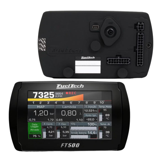
Presentation The FuelTech FT500 is a real-time fully programmable fuel injection system which allows the adjustment of fuel and ignition maps according to the engine needs. Programming can be done directly on the module through its 4.3" touchscreen or via FT Manager Software with USB high-speed communication. Maps and compensations can be set as 2D or 3D tables, and its resolution can be changed via FT Manager Software. -
Page 3: Table Of Contents
Summary Presentation ..................................3 Summary ....................................4 Warranty terms..................................7 Characteristics ..................................8 Harness connections – 24 way connector ..........................10 Harness connections – 16 way connector ..........................11 Auxiliary outputs ....................................12 Internal MAP sensor ..................................12 USB port ......................................12 FuelTech CAN network .................................. - Page 4 14.4 Fuel pump ......................................43 14.5 Variable camshaft control/Powerglide gearbox ........................44 14.6 Progressive nitrous control ................................44 14.7 Boost control..................................... 45 Electronic throttle control ..............................46 15.1 Connection table – throttle bodies and pedals ........................46 Sensors and Calibration ..............................47 16.1 TPS calibration ....................................
- Page 5 20.6 Cooling fans 1 and 2 ..................................69 20.7 Air conditioning ....................................69 20.8 Fuel pump ......................................69 20.9 Camshaft control.................................... 70 20.10 Progressive nitrous control ................................70 20.11 Boost control..................................... 71 20.12 Boost activated output ................................. 71 20.13 Tachometer output ..................................71 Drag race features ................................
-
Page 6: Warranty Terms
Warranty terms The use of this equipment implies the total accordance with the terms described in this manual and exempts the manufacturer from any responsibility regarding to product misuse. Read all the information in this manual before starting the product installation. This product must be installed and tuned by specialized auto shops and/or personnel with experience on engine tuning. -
Page 7: Characteristics
Characteristics Inputs and specifications Max RPM: 32000RPM 103 psi internal MAP sensor (7 bar - absolute), 14.7psi of vacuum and 88psi of positive pressure (boost) touchscreen with 16.8 million colors 375MIPS processor (Processing capabilities Millions of Instructions per Second) Otto cycle engine control: 1, 2, 3, 4, 5, 6, 8, 10 and 12 cylinders and 2, 3 and 4 rotors 2 injector banks (staged injection banks A and B) Injection time resolution 0.001ms... - Page 8 Weight: 280g (10oz) Package contents: 1 FT500 ECU 1 wiring harness 1 USB flash drive (contains FT Manager Software, FT guides, etc.) 1 Mini USB cable 1 FT500 installation guide 1 Smart clip support ECU dimensions: 141mm (5,5in) x 82mm (3,2in) x 33mm (1,3in)
-
Page 9: Harness Connections - 24 Way Connector
Harness connections 24 way connector Wire color Function Information Blue #1 Blue output #1 Blue #2 Blue output #2 Blue #3 Blue output #3 These outputs are usually used for injector control. When needed, Blue #6 Blue output #6 they can be configured as auxiliary outputs. Blue #7 Blue output #7 Blue #8... -
Page 10: Harness Connections - 16 Way Connector
Harness connections 16 way connector Wire color Function Information White #1 White input #1 Standard: O2 sensor input White #2 White input #2 Standard: two-step input These inputs can be set up as any White #3 White input #3 Standard: air conditioning button kind of analog or digital sensor. -
Page 11: Auxiliary Outputs
Auxiliary outputs in many different ways, they have different capacities according to the function. Below is some important information about them: Blue outputs [#1 to #8]: by standard, used as injector outputs. Each one of them can control up to: ... -
Page 12: First Steps With Ft500 Read Before Installation
First steps with FT500 read before installation This chapter is a step-by-step guide that must be followed to start FT500 basic setup before electric installation, as the function of each wire may vary according to engine setup (number of cylinders, injectors control mode, ignition coils and auxiliary outputs). -
Page 13: Getting To Know The Ecu
Getting to know the ECU Main Menu Navigation through touchscreen is intuitive, because the ECU display makes the access to information very easy, eliminating physical buttons. So, all changes on maps, setups and functions are done by light touches on the screen. To enter menus, press the screen twice, just like a double click. -
Page 14: Dashboard Screen
Advanced edition mode In this mode, fuel and ignition maps are shown in 3D tables, as well as individual fuel and ignition trims. Navigation is pretty simple with useful features to help you: On-screen mini map on the left corner a mini map shows the actual position on the table (yellow square for primary bank, purple square for secondary bank) and the real time MAP and RPM conditions of the motor (yellow square). -
Page 15: Diagnostic Panel
Diagnostic panel The Diagnostic Panel is a tool used to detect anomalies on FT5 inputs, outputs, sensors and actuators. In order to access it, touch its icon at the main menu. Information is split on 6 pages: Page 1: general engine information; ... -
Page 16: Engine Settings
Engine settings Engine setup Engine type and number of cylinders: select the type of engine, piston or rotary and the number of cylinders or rotors. Engine limits: setup the maximum RPM and maximum boost. Maximum engine speed: setup the engine maximum RPM. All fuel and timing maps will be created with its last point on this RPM. -
Page 17: Rpm Signal
Main tables Main table by MAP: this mode is indicated for turbo or naturally aspirated engines. because, the engine vacuum varies under different loads, even with the throttle on the same position. TPS compensation is available on fuel and timing maps. Main table by TPS: this option is mostly used on naturally aspirated engines with aggressive camshafts, when this causes the vacuum on idle and under low load conditions to be unstable. - Page 18 RPM sensor Select the RPM sensor used on the vehicle, magnetic or Hall Effect. VR internal ref: this option may only be selected when using a FT500 on an installation previously made for older ECUs of FT line (FT200, FT250, FT300, FT350 or FT400), where the shielded cable is a single way (white wire + shield).
-
Page 19: Ignition
Cam sync sensor edge: telling which one is the correct option (without an oscilloscope), select the option Falling Edge. If the engine starts with misfires, change this parameter to Rising Edge. Ignition This menu sets everything related to the ignition control mode and there is Default mode (configurable through the ECU or PC) and Disabled maps are unavailable and only the fuel control is enabled. -
Page 20: Fuel Injection
Fuel injection Default: This mode makes available the options that are commonly used for the majority of engines, with standard injection angles and configurations. Custom: This mode enables all the options related to the fuel control, as customizable injection angles, etc. When using this mode, fuel injection configuration can only be done through a PC with FT Manager Software. -
Page 21: Pedal/Throttle
Pedal/throttle Standard input for TPS sensor signal is #11, but it is possible to set this input on any available input. Pedal/Throttle calibration must be performed as shown in chapter 13.4. Electronic throttle control First data to be inserted on the ECU when using electronic Throttle is its code (not the throttle part number). This code is found on the FT Manager Software. - Page 22 Electronic throttle control motor outputs Select the outputs that will control the two wires from the throttle motor. By standard they are yellow #3 (motor 1A) and yellow #4 (motor 1B). In case these outputs are already being used by another kind of control, use outputs yellow #1 (motor 1A) and yellow #2 (motor 1B).
-
Page 23: Idle Actuators
Idle actuators This menu allows you to select the idle actuator used on the engine and the outputs that will control it. After this quick setup, the idle speed parameters must be done according to chapter 20.2. control idle speed by ignition timing as configured in menus. -
Page 24: Fuel Injectors Deadtime
Fuel injectors deadtime All fuel injectors, as they are electromechanical valves, have an opening already received an opening signal, but still has not started to inject fuel. This parameter considers, as a standard value, 1.00ms for high impedance fuel injectors. For low impedance injectors using Peak and Hold driver, set the deadtime to 0.80ms. -
Page 25: Fueltech Base Map
FuelTech base map the next step is to generate the FuelTech base map, a function that generates fuel and ignition maps to be used as a start point for the engine tuning. FuelTech base map is a function that calculates fuel and ignition maps based on the information you provide on Make sure the information provided is correct and coherent. -
Page 26: Electrical Installation
Electrical installation As FT500 wires are fully configurable according to the installation needs, it is very important that the step by step guide shown on chapter 5 is followed before starting the electrical installation. This way the wiring harness connection table is automatically filled as shows the example below: Primary bank: 4 injectors on sequential mode (blue wires #1 to #4) Secondary bank: 4 injectors on semi sequential mode... - Page 27 Black wire This wire is responsible for signal ground to the ECU so, it must be connected terminal, with no seams. Under no hypothesis, this wire can be connected to the vehicle chassis or split with the ECU black/white wire (power ground). This will cause electromagnetic interference and other problems hard to diagnose and solve.
-
Page 28: Ft500 Connection On Previous Ft Installation
10 FT500 connection on previous FT installation FT500 can be installed on vehicles that were already using older FT ECUs without the need to rewire everything. However, a few points must be checked and changed. The best option is to perform a new installation, with FT500 original harness, following the recommendations contained on this guide. -
Page 29: Ignition Calibration
10.3 Ignition calibration The ignition calibration screen on FT500 has the same parameters that previous FT ECUs, the difference is that they are in the same screen. After calibrating the ignition, the 1st tooth index position is automatically changed on the 10.4 Injection time differences between FT500 and previous FT ECUs Some differences may be observed when tuning a FT500 based on a previous FT ECU map (FT200, FT250,... -
Page 30: Fuel Injectors
11 Fuel injectors FT500 has 8 outputs to control fuel injectors (blue wires #1 to #8). Each one of them can control up to 6 injectors with internal resistance above 10 Ohms (saturated injectors) or up to 4 injectors with internal resistance above 7 Ohms. -
Page 31: Ignition
12 Ignition FT500 has 8 ignition outputs that can be used according to the needs of the project, controlling a distributor or a crank trigger. 12.1 Ignition with distributor When using this ECU with a distributor, the only active ignition output is gray #1. This wire must trigger an ignition module or a coil with integrated igniter. -
Page 32: Ignition With Crank Trigger
12.2 Ignition with crank trigger When controlling the ignition in distributorless systems, wasted spark or individual coils per cylinder are needed. In this case, coils are triggered by different outputs, according to the number of cylinders. Ignition outputs (gray wires) are triggered according to the firing order set up on the ECU. Example: 4 cylinder engine with individual coils Gray outputs are selected automatically, according to the number of cylinders. - Page 33 Individual coils connections Cars where usually Coil Type Pin connection found Pin 1: Ignition power (from SparkPRO or similar) Bosch No internal igniter Fiat Marea 2.0T, 2.4 Pin 2: Power ground (engine head) 0 221 504 014 Pin 3: Switched 12V from relay Pin 1: Power ground (engine head) Fiat Punto/Linea 1.4 T-Jet...
- Page 34 Wasted spark coils connections Cars where usually Coil Type Pin connection found No integrated Bosch Fiat Palio, Siena, Uno 1.0, 1.5, Pin 1: Ignition power (from SparkPRO or similar) igniter (two spark F000ZS0103 1.6, Tempra 2.0 Pin 2: Switched 12V from relay plug outputs) Bosch 4 cylinders Celta, Corsa, Gol Flex, Meriva,...
-
Page 35: Sensors And Actuators
13 Sensors and actuators FT500 has some pre-defined sensors s possible to setup any kind of analog sensor on its inputs or even to connect it and read a sensor in parallel with the OEM ECU. This configuration is done on the custom mode through software FT Manager and USB cable on a PC. -
Page 36: Crank Trigger/Rpm Sensor
13.5 Crank trigger/RPM sensor To control fuel and ignition, this ECU is able to read magnetic and Hall Effect sensors. 13.5.1 Distributor To read RPM signal from a Hall Effect distributor, it should have a sensor with at least 3 pin and have the same than the engine has number of cylinders 13.5.2 Crank trigger The crankshaft trigger wheel is responsible for informing the exact position of the crankshaft to the electronic... - Page 37 Honda Distributor Honda 92/95 Honda 96/00 Distributor Pin FT500 connection Configuration (wire color) (wire color) With stock Honda coil and igniter: connect to gray wire #1 Honda Yellow/green Yellow/green Ignition trigger input Distributor With multi-coils, and external igniter: do not connect Blue/green White 2-core shielded cable red wire...
- Page 38 1, 2, 3, 4, 5, 8, 10 and 24 teeth: options available according to the number of engine cylinders. When having these trigger wheels, the use of a camshaft position sensor is mandatory, in order to maintain the synchronization of the parts.
-
Page 39: Crankshaft Trigger Sensor
13.5.3 Crankshaft trigger sensor When controlling the ignition with a trigger wheel, it is necessary to have a sensor that reads the signal from its teeth and informs the engine position to the injection. There are two types of crankshaft trigger sensors: ... -
Page 40: Camshaft Position Sensor
13.6 Camshaft position sensor This sensor tells the ECU when the cylinder #1 is reaching its TDC on the compression stroke. With this information it is possible to control ignition and fuel injection in sequential mode. Installation and alignment of this sensor are pretty simple. -
Page 41: Step Motor Idle Speed
13.8 Step motor idle speed Its control is done through the four yellow outputs of the 16-way connector, also used for electronic throttle control. After selecting the idle speed control as step motor (as guides chapter 7.6) the four yellow outputs are automatically set Below are some known step motor connections. -
Page 42: Auxiliary Outputs
14 Auxiliary outputs The current capacity of these outputs is 0.7A, and therefore they can drive solenoids or relays , the installation of a fuse equivalent to the charge is recommended. The auxiliary outputs have an overload protection system, with automatic current cut-off. -
Page 43: Variable Camshaft Control/Powerglide Gearbox
14.5 Variable camshaft control/Powerglide gearbox The camshaft control systems that use solenoid valve type NO/NC VTEC can be controlled switched by PWM (such as Toy Ti), it is possible to manage it through the Boost Control function, as long as its characteristics (power, current, etc.) are within the auxiliary output limits. -
Page 44: Boost Control
14.7 Boost control This auxiliary output configuration allows the driving of a boost pressure control solenoid. FuelTech recommends using a 3-way N75 solenoid, found in the original 4 and 5- cylinder VW/Audi Turbo models, which can be directly switched through the auxiliary output. Such solenoid valve controls the pressure on the top and bottom parts of the wastegate valve, changing the engine manifold pressure with which the latter opens. -
Page 45: Electronic Throttle Control
15 Electronic throttle control Electrical installation of an electronic throttle on FT500 is pretty simple. Check the example diagram below: Yellow #1 wire (pin 13 of the 16-way connector) must be connected to the throttle input corresponding to the Motor 1 input. -
Page 46: Sensors And Calibration
16 Sensors and Calibration This chapter has the final steps before the first engine start. It basically guides the user through checking sensor readings and calibrating engine actuators. 16.1 TPS calibration To perform this calibration, it is very important that the engine is not running, because the throttle is fully opened and closed. -
Page 47: Fuel/Oil Pressure Sensors Inputs
16.3 Fuel/oil pressure sensors inputs In this menu are the settings for fuel and pressure sensors. There is a predefined configuration for PS-10A, PS10- B and VDO pressure sensors, but any kind of analog sensor with 0-5V signal can be used. This configuration is done through the PC and software FT Manager. -
Page 48: O2 Sensor Inputs #1 And #2
16.5 O2 sensor inputs #1 and #2 O2 sensor signal input can be setup on any sensors input of this ECU. It is even possible to read two O2 sensors simultaneously and show them on the screen. For wide band O2 sensors, it is necessary to use a wide band conditioner, for narrow band O2 sensors, direct connection is allowed. -
Page 49: Traction Type
16.6 Traction type Set here if the vehicle is FWD, RWD or AWD. This information is used with the time based speed control. 16.7 Wheel speed (front/rear) This menu gathers the wheel speed (front and rear) reading setup. In the first screen, set if the reading is through FT500 sensor input (white wire) or through FuelTech GearController CAN port. -
Page 50: Driveshaft Rpm
16.8 Driveshaft RPM This menu is used to setup the driveshaft RPM reading. Select the FT500 sensor input to be used and insert the trigger wheel number of teeth With the driveshaft speed and the tire dimensions, it is possible to calculate the traction wheel speed. If you want to use a driveshaft RPM sensor instead of screen. -
Page 51: Gear Detection
16.10 Gear detection There are five different ways to perform the gear detection: (1) By RPM drop (for drag race only does not require wheel speed sensor); (2) By analog gear position sensor (only transmissions originally equipped with this sensor - does not require wheel speed sensor);... - Page 52 The fourth mode increases the gear counting by each pulse received on a white input. Set in which edge the count should be increased (default: falling edge). Configure an input as "Gear Detection" and connect the device that will send the pulse to increase the counting. This mode cannot detect downshifts and requires the 2-step to be used to reset the counter;...
-
Page 53: Starting The Engine For The First Time
17 Starting the engine for the first time This chapter shows final steps before the engine first start and guides the user through checking and calibrating all the sensors and actuators of the motor. 17.1 First engine start Try not to push the starter motor and the coils by cranking the starter too long on the first start. Check if the fuel pump is turned on and if there is fuel pressure on the line. - Page 54 Calibration of the Crank Angle Sensor Ignition Timing The ignition calibration on rotary engines is performed just like any other engine. By entering this screen, the ECU locks the ignition timing to 20° by default. Timing light will be used to read ignition timing marks in the damper and spark on Leading Rotor #1. Put your timing light on 0°...
-
Page 55: Fuel Tables Adjust
18 Fuel tables adjust 18.1 Main fuel table Editing mode for main fuel table is on basic mode by default, easily configured for advanced mode through FTManager Software and a PC. On FTManager, it is possible to edit the map cell ranges of MAP/TPS, RPM, etc., making it possible to increase the detail level on the maps where a fine tuning is needed. -
Page 56: Rpm Compensation
18.3 RPM compensation This compensation is a percentage applied over the injection time and is only available when the ECU is set up on the basic mode. On the advanced mode, this RPM compensation is already included in the 3D main fuel table. It is very important to check data continuity, avoiding incoherent values that may produce abrupt changes on the RPM graphic. -
Page 57: Tps Idle Fuel Table
Auxiliary O2 closed loop: Aux by time (2-step): This feature allows the creation of a 16 points time based O2 target table after the 2-step deactivation, which will overwrite the main O2 target table during the time setup on this auxiliary table. To trigger the 2-step, TPS must be above 50% or RPM must hit the 2-step rev limiter. -
Page 58: Acceleration Fuel Enrichment And Decay
18.6 Acceleration fuel enrichment and decay Acceleration enrichment is a fuel increase when the throttle is suddenly opened. Max fuel on pump: value added to the actual injection time when a quick throttle variation is detected. There are two RPM and injection time parameters to be set. With them, the ECU creates an acceleration fuel table that interpolates the values between these two positions. -
Page 59: Engine Temperature Compensation
18.7 Engine temperature compensation This compensation is applied based on the engine temperature sensor, which, in water-cooled cars, must be at the cylinder head reading the water temperature, and in air-cooled engines, must be reading the oil temperature. Compensations based on engine temperature are only available when the sensor is connected to the injection system. -
Page 60: Engine Start
18.12 Engine start This function is essential when starting the engine, as it needs a greater injection pulse to initiate its operation, especially if the vehicle runs on ethanol or methanol. The amount of fuel necessary to start the engine also depends very much on its temperature, as the colder it is, the more fuel is needed. -
Page 61: Gear Shift Fuel Enrichment
18.17 Gear shift fuel enrichment This function enables fuel compensation when a gear shift is detected, that allows building a time based enrichment table. 18.18 Fuel injection phase angle table This table changes the moment, during the engine cycle, where the injectors opens or closes and is only available when the fuel injection is being controlled in sequential mode. -
Page 62: Ignition Tables Adjust
19 Ignition tables adjust 19.1 Main ignition table The editing mode of this table is, by standard, the simplified 2D table, being possible to change it to advanced 3D table via FTManager software. Through the software is also possible to edit the range interval of MAP, TPS and engine RPM on the maps. This makes possible to increase the detail level on specific ranges where a fine tuning is needed. -
Page 63: Map/Tps Compensation
19.3 MAP/TPS compensation This table changes according to the main map configuration (MAP or TPS). When the main ignition table is setup by MAP, this table is a compensation by TPS. When the main ignition table is setup by TPS, this compensation is by MAP. 19.4 Engine temperature compensation This map represents a compensation on the advance or retard angle... -
Page 64: Gear Compensation
19.10 Gear compensation This compensation allows advancing or retarding the ignition timing according to the engaged gear. This table applies the compensation in the main ignition table according to engaged gear and RPM. To enable this option, gear change detection must be enabled. It is possible to set up to 6 compensation tables (6 gears). -
Page 65: Other Functions
20 Other functions This menu allows the adjustment of all functions that modify the operation of auxiliary outputs and compensations of idle speed, etc. 20.1 Internal datalogger This function is used to log all the engine data read by FuelTech ECU. The Internal Datalogger can record up to 64 channels like: injection time (banks A and B), injectors duty cycle (banks A and B), timing, engine rpm, auxiliary output status, TPS, coolant and air temperature, oil and fuel pressure, O2 sensor, two-step button, MAP sensor, camshaft position sensor and battery voltage. -
Page 66: Idle Speed Control
20.2 Idle speed control This ECU can control idle speed through electronic throttle, step motor, PWM valve and by timing. To enable the idle speed control by electronic throttle, it is needed to you can follow this menu to setup idle parameters. Idle speed by timing: this control uses a target RPM for idle speed and works advancing and retarding the engine timing to keep the engine running near the specified RPM. -
Page 67: Deceleration Cut-Off
20.3 Deceleration cut-off This function cuts-off fuel every time the throttle is not being pressed and the engine is above the chosen RPM. It results in a great gain of economy, because fuel is not wasted when the car is let run with gears engaged, when engine break is being used, or when the driver steps off the gas to make turns or in regular transit situations. -
Page 68: Air Conditioning
20.6 Cooling fans 1 and 2 The electric fan control in the engine cooling system is based on the temperature in which it is expected to be activated and disabled. One can establish that the electric fan must be activated when the engine reaches 194 F and turned off when it cools to 180 This ECU can control up to two cooling fans on different... -
Page 69: Camshaft Control
20.9 Camshaft control This function allows the control of a variable valve timing control system (or a drag racing 2-gear automatic system). Select the output used to control the camshaft solenoid, and then, inform the RPM that the solenoid must be turned on. -
Page 70: Boost Control
20.11 Boost control This feature allows the control, through PWM, of a solenoid valve that manages the wastegate valve, therefore regulating the boost pressure. FuelTech recommends using a 3-way N75 solenoid. For more information about its installation, see chapter 14.7 in this manual. The first parameter to be configured is the TPS percentage, above which the Boost Control will start to pulse the control solenoid. -
Page 71: Drag Race Features
21 Drag race features This menu gathers all options normally used in drag race applications. All the time based features start after releasing the 2-step button which indicates the moment when the vehicle launched. 21.1 Burnout mode The Burnout Mode is a function used to facilitate the processes of warming up the tires and using the two-step. When pressing the two-step button, the two-step function is activated. -
Page 72: 2-Step Rev Limiter
21.3 2-step rev limiter The two- ative terminal. When pressing the two-step button, usually installed on the steering wheel or driven by a launch control / transbrake switch, the system activates an ignition cut in a programmable RPM (generally between 3000 RPM and 6000 RPM), with a retarded ignition timing (normally equal or lesser than 0 ), and a mixture enrichment given in percentage (also programmable). -
Page 73: Time Based Fuel Enrichment
21.6 Time based fuel enrichment Enables a time based fuel compensation that starts after the 2-step deactivation. This compensation is a time (seconds) versus compensation (%) feature. After you enter the table, a graph will be displayed. 21.7 Time based advance/retard timing Enables a time based timing compensation that starts after the 2-step deactivation. -
Page 74: Time Based Speed (Cut)
21.10 Time based speed (cut) This feature is the same as the time based RPM (cut) but instead of use the engine RPM, it uses the wheel speed (with a wheel speed sensor or by calculate speed) or the driveshaft RPM. It will perform ignition cut to keep the wheel speed/driveshaft RPM under a predefined curve. -
Page 75: Pro-Nitrous
Note that the speed and retard curves shown on the graph form speed and retard zones. They have the following characteristics: When below the curve A, there is no retard applied to the engine; When the speed/RPM is equal to the programmed curve A, the ignition retard is equal to the programmed in curve A;... -
Page 76: Time Based Output
Pro Nitrous fuel tables On the first screen is the configuration that allows setting a delay to start the fuel compensation, based on the time that the nitrous shot takes to get to the combustion chamber. Since the injectors are closer to the combustion chamber than the nozzles/foggers, the purpose is that the fuel and nitrous get to the combustion chamber at the very same time. -
Page 77: Alert Settings
22 Alert settings 22.1 Safe mode RPM limiter Safe mode protects the engine whenever an alert is activated, limiting max engine RPM while the alert condition is still happening. 22.2 Alerts The configuration of alerts allows the programming of sound and visual alerts whenever a dangerous situation to the engine is detected. -
Page 78: Favorites
Injector duty cycle: setup a percentage value that indicates saturation. Oil pressure: setup considered for low oil pressure. Also, select how the ECU reacts when this alert is activated. Minimum oil pressure: setup a minimum oil pressure value above X RPM and how the ECU reacts. -
Page 79: Interface Settings
24 Interface settings 24.1 LCD backlight settings Adjust LCD brightness and select between night and day modes. 24.2 Alert sound settings This parameter allows for the setting the volume of sounds generated by touching the display. When the mute option is selected, the ECU is silent when the screen is touched. -
Page 80: Startup Screen Selection
24.4 Startup screen selection Select the screen shown right after the ECU is turned on. In case the with a user password, the ECU will ask for the user password. 24.5 Clear peaks At the Instrument Panel, values read by the sensors connected to the module are displayed in real time. -
Page 81: Measurement Units
24.7 Measurement units In this menu it is possible to change the measurement unit for some parameters as pressure, temperature, speed and O2 readings. Pressure units: bar, PSI or kPa; Temperature units: °C or °F; O2 sensor units: Lambda, AFR Gasoline or AFR Methanol; Speed units: km/h or mph. -
Page 82: File Manager
25 File manager With the file manager it is possible to alternate between the 5 memories positions stored in the ECU. With this, you can have up to 5 totally different calibrations for different fuels or engines. 25.1 FuelTech base map generator This function generates a base map that can be used to start engine menu to create a base map more accurate to the engine needs. -
Page 83: Rotary Engines Setup
26 Rotary engines setup The crank angle sensor (CAS) has two (2) trigger wheels that provide different signals to the ECU. As shown in picture, the bottom wheel is a 24 teeth trigger that provides the RPM signal and position of the eccentric shaft. The top wheel is a 2 teeth trigger that provides information of the position of the rotor. -
Page 84: Crank Angle Sensor Wiring
26.2 Crank angle sensor wiring The stock distributor will be read by FT as a Crank Angle Sensor and Camshaft Position Sensor. connect the FT to your stock Mazda distributor: Function Distributor Wire FuelTech Wire FuelTech Pin 24 teeth signal (crank signal) Red from 2 core shielded cable 24 teeth sensor negative White... -
Page 85: Ignition Coils Wiring
26.4 Ignition coils wiring After setting everything up, the ignition outputs of the ECU are ready to be connected to your coils or ignition modules. FT ECU ignition outputs cannot be connected directly to dumb coils, only to smart coils (coils with integrated ignition module) or ignition modules. -
Page 86: Ft500 Electrical Diagram
27 FT500 electrical diagram 27.1 FT500 4 cylinders sequential fuel SparkPRO-2 wasted spark coil... -
Page 87: Ft500 - 4 Cylinders - Sequential Fuel - Sparkpro-4 - Coil-On-Plug
27.2 FT500 4 cylinders sequential fuel SparkPRO-4 coil-on-plug... -
Page 88: Ft500 - 2 Rotors - Sequential Fuel - Sparkpro-4
27.3 FT500 2 rotors sequential fuel SparkPRO-4...
Need help?
Do you have a question about the FT 500 and is the answer not in the manual?
Questions and answers