Table of Contents
Advertisement
Quick Links
Advertisement
Table of Contents

Related Manuals for Kongsberg Seapath 320

Summary of Contents for Kongsberg Seapath 320
- Page 1 ® Seapath Technical Description...
- Page 2 First issue of this manual Rev. 2 Copyright © 2010 Kongsberg Seatex AS. All rights reserved. No part of this work covered by the copyright hereon may be reproduced or otherwise copied without prior permission from Kongsberg Seatex AS. Disclaimer The information contained in this document is subject to change without prior notice.
-
Page 3: Table Of Contents
Technical Description Table of contents PRODUCT DESCRIPTION ........... 1 Purpose and application ................... 1 System components ....................2 1.2.1 The Processing Unit ....................3 1.2.2 The HMI Unit ......................4 1.2.3 The MRU 5 ....................... 5 1.2.4 ... - Page 4 Seapath 320 2.4.5 GNSS antenna ......................13 External interfaces ....................14 2.5.1 Processing Unit ....................... 14 2.5.2 HMI Unit ........................ 14 2.5.3 MRU Unit ....................... 14 Product safety ......................14 2.6.1 Processing Unit ....................... 14 ...
- Page 5 Technical Description 3.2.5 Monitor ........................32 Survey of sensors on vessels .................. 33 3.3.1 Vessel reference system ..................33 3.3.2 MRU ........................33 3.3.3 GNSS antennas ....................... 34 3.3.4 Gyro ........................34 3.3.5 Survey accuracy ...................... 34 3.3.6 Cabinet mounting ....................35 CONFIGURATION ............
- Page 6 Seapath 320 5.10 Tools menu ......................68 5.10.1 U tilities ........................68 5.10.2 D iagnostics ......................68 5.10.3 L og .......................... 69 5.11 System menu ......................69 5.11.1 C onfiguration ......................70 5.11.2 I nformation ......................70 ...
- Page 7 Technical Description Figure 14 Location of system parts ................30 Figure 15 Change system mode menu ................37 Figure 16 NavEngine configuration ................38 Figure 17 NavEngine Configuration view ..............38 Figure 18 History button ....................39 ...
- Page 8 Seapath 320 Figure 47 Times Series view showing data for roll, pitch, heave and heading ..... 66 Figure 48 View menu ....................67 Figure 49 Dusk mode ....................68 Figure 50 Day black mode .................... 68 ...
- Page 9 Technical Description Abbreviations Aft Perpendicular. The vertical intersection of the design waterline at the stern, alternatively the centreline of the rudder stock. Base Line. Is the same as the keel for a vessel with horizontal keel line. Coarse/Acquisition Circular Error Probability Centre of gravity.
- Page 10 Seapath 320 MRU 5 Motion Reference Unit, model 5. This is the IMU within the Seapath measuring dynamic linear motion and attitude. A MRU consists of gyros and accelerometers. MSAS Multifunctional transport Satellite-based Augmentation System (SBAS-Japan) NAD27 North American Datum of 1927 NMEA National Marine Electronics Association.
- Page 11 Technical Description Terminology Alignment Is the process of adjusting the current internal navigation frame in the instrument to the true external frame. Antenna bracket Is the arrangement for mounting the GPS antennas. Antenna holder Is the arrangement on board the vessel for mounting the antenna bracket to.
- Page 12 A rotation about the vertical axis is positive when turning Eastward (Clockwise) when the vehicle cruises in North direction. Normally, yaw means the dynamic yaw motion. References M300-62, Seapath 320 Installation Manual NMEA 0183 Standard for Interfacing Marine Electronic Devices, Version 3.00 RTCM Recommended Standards for Differential Navstar GPS Services, Version 2.3...
- Page 13 Export Control and may be subject to restrictions if re-exported from your country. Restrictions in guarantee The liability of Kongsberg Seatex is limited to repair of the Seapath system only under the given terms and conditions stated in the sales documents. Consequential damages such as customer's loss of profit or damage to other systems traceable back to Seapath malfunctions are excluded.
- Page 14 Seapath 320 Restrictions in use The Seapath function is based on GNSS signals and requires free sight to the sky, minimum four visible satellites, PDOP value less than 6 and otherwise normal conditions to operate. It is designed for use on board marine surface operated vehicles with linear acceleration less than ±30 m/s...
-
Page 15: Product Description
Technical Description 1 PRODUCT DESCRIPTION The Seapath 320 is a positioning, attitude and heading sensor. The product combines inertial technology together with GPS and GLONASS satellite signals. Core components in the product are the MRU 5 inertial sensor, the two combined GPS/GLONASS receivers, the Processing and HMI Unit. -
Page 16: System Components
Seapath 320 Figure 1 Typical information shown to the user System components The Seapath 320 comprises the following main components, which are physically separated: • A Processing Unit for I/O and calculations. • An HMI Unit with MONITOR, keyboard and PC mouse. -
Page 17: The Processing Unit
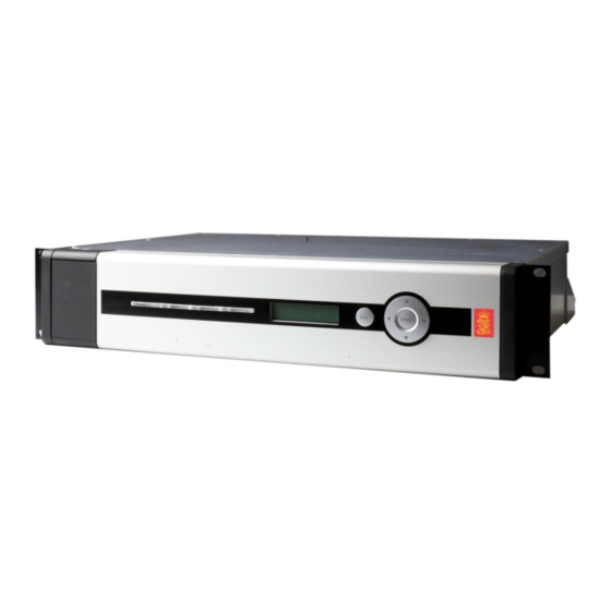
Technical Description Figure 2 System architecture 1.2.1 The Processing Unit The Processing Unit is designed to fit standard 19-inch racks and is typically installed on the bridge or in the instrument room. The Processing Unit comprises the following main parts: •... -
Page 18: The Hmi Unit
Seapath 320 Figure 3 Front panel of Processing Unit The rear panel of the Processing Unit contains communication interface ports for interfacing to external sensors. These ports are individually galvanically isolated. Figure 4 Rear panel of Processing Unit 1.2.2 The HMI Unit The HMI Unit is designed to fit 19-inch racks and is typically installed on the bridge or in the instrument room. -
Page 19: The Mru 5
Technical Description Figure 6 Rear panel of HMI Unit 1.2.3 The MRU 5 The Seatex MRU 5 is specifically designed for motion measurements in marine applications. The unit incorporates 3-axis sensors for linear acceleration and angular rate, along with complete signal processing electronics and power supply. -
Page 20: The Gnss Antennas And Antenna Bracket
The housing cylinder should, however, not be removed by anyone else than Kongsberg Seatex. The MRU is integrated in Seapath, and all digital data are routed through the Processing Unit. -
Page 21: Networked Architecture
Technical Description Figure 9 Antenna Bracket Figure 10 Side view of GNSS antenna installation Networked architecture The Navigation Engine runs all critical computations independent of the HMI Unit to ensure continuous and reliable operation. Navigation Engine runs in a safe mode protected from unintended user operations. - Page 22 Seapath 320 Man_techn_seapath320/rev.1...
-
Page 23: Technical Specifications
Technical Description 2 TECHNICAL SPECIFICATIONS Performance data Roll and pitch accuracy for ±5° amplitude ..........0.02° RMS (*) Heading accuracy with 2.5 metre antenna baseline ......... 0.075° RMS Heading accuracy with 4 metre antenna baseline ..........0.05° RMS Scale factor error in roll, pitch and heading ........... 0.08 % RMS Heave accuracy .............. -
Page 24: Monitor, 17-Inch Lcd
Seapath 320 Weight ........................3.8 kg Colour ..................... Front anodized natural 2.2.3 Monitor, 17-inch LCD Type ..................Samsung SyncMaster 710n Width ........................380 mm Height ........................383 mm Depth ........................170 mm Weight ........................3.8 kg Colour ......................Black and silver 2.2.4... -
Page 25: Antenna Bracket
Technical Description Colour ........................Black Material ......................Aluminium Enclosure protection ....................IP-65 2.2.7 Antenna Bracket Type ........................M320-21 Length ........................2560 mm Width ........................75 mm Height ........................40 mm Weight ........................6.6 kg Colour ......................Grey RAL 7035 2.2.8 GNSS antenna Type .................... -
Page 26: Hmi Unit
Seapath 320 Power consumption ..................Max. 75 W Batteries .............. None, connection to UPS recommended 2.3.2 HMI Unit Voltage ..................100 - 240 V AC, 50/60 Hz Power consumption ................... Max. 40 W Batteries .............. None, connection to UPS recommended 2.3.3... -
Page 27: Hmi Unit
Technical Description 2.4.2 HMI Unit Enclosure material .................... Aluminium Operating temperature range ..............-15 °C to +55 °C Recommended operating temperature ........Room temperature (+20 °C) Storage temperature ................. -20 °C to +70 °C Operating humidity ..............Max. 95 % non-condensing Storage humidity .................. -
Page 28: External Interfaces
Seapath 320 External interfaces 2.5.1 Processing Unit Serial ports ........... 6 non-dedicated isolated ports, RS-232 or RS-422 ..........Isolated Com1 and Com2, 9 pin DSub, RS-232 or RS-422 Baud rate ..................Up to 115 200 bytes/sec LAN ......................4 Ethernet ports USB .................. -
Page 29: Radio Frequencies
Technical Description Radio frequencies 2.7.1 GNSS antenna L1 ......................1588.5 ± 23.0 MHz L2 ......................1236.0 ± 18.3 MHz LNA gain (typical) ....................27 dB 2.7.2 GNSS receiver GPS L1 ......................1575.42 MHz Glonass L1 ... 1602.0 MHz for Fk=0 where k=(-7 to +13) channel spacing 562.5kHz Data outputs 2.8.1 Processing Unit... -
Page 30: Data Inputs
Seapath 320 Data inputs 2.9.1 Processing Unit DGPS corrections ..............RTCM-SC104 v. 2.2 and 2.3 ........................Trimble CMR DGLONASS corrections ..............RTCM-SC104 v. 2.2 Gyro compass ............. NMEA 0183 HEHDT and HEHRC ..................... Robertson LR22 BCD format 2.10 Compass safe distance 2.10.1 Processing Unit... -
Page 31: Gnss Antenna Cables (Coax)
Minimum bend radius ....................32 mm Flame retardation ........... CATV, UL1581, IEC 332-3, IEEE383 Coax connectors ..............Huber+Suhner 11 N-50-9-9 If the antenna cables are not delivered by Kongsberg Seatex, make sure that the cables meet the following electrical specifications: Insertion loss (max.) 15 dB (at 1.6 GHz) -
Page 32: Interfaces Processing Unit
Seapath 320 2.12 Interfaces Processing Unit The rear panel of the Processing Unit contains communication interface ports for interfacing to external equipment. In addition, a USB and a LAN port are situated at the front together with the power switch. -
Page 33: R S-422 A And B Signal Definition
Technical Description Connector Type Connected to ALARM 3 pins terminal, relay External alarm system 10 pins terminal, RS-422 MRU5 or MRU5+ 10 pins terminal Not in use 1PPS 6 pins terminal External equipment ANALOG OUT 10 pins terminal User configurable ANALOG IN 6 pins terminal Not in use... -
Page 34: Figure 12 Connector Board
Seapath 320 Pin no. RS-232 Pin no. RS-232 DCD1 DSR1 RXD1 RTS1 TXD1 CTS1 DTR1 Table 4 Pin layout of Com 1 and Com 2 2.12.2.2 Connector board The screw terminal pin layout on the connector board at the rear of the PU is described below. -
Page 35: Table 5 Pin Layout Of Com 9 Through Com 14
Technical Description Pin no. Signal RS-422 RS-232 RX_A RX_B TX_A TX_B Table 5 Pin layout of Com 9 through Com 14 PPS signal A 1 pulse-per-second (1PPS) signal synchronized with GNSS time is available from the 6 pin terminal at the rear of the Processing Unit. This RS-422 1PPS signal originates from the GNSS receiver within the Processing Unit. -
Page 36: Figure 13 External Alarm Connection Diagram
Seapath 320 → For description of the format for these messages, see the Seapath 320 Installation Manual. Relay - alarm signal The Processing Unit has a built-in alarm functionality and can be connected to an external alarm. An alarm will open the alarm relay, which can be used to trigger an external alarm. -
Page 37: Table 8 Pin Layout Of Analog Out
Technical Description Analog output Three analog output channels are available on the Analog Out 10 pin terminal. The variables available for analog output are roll, pitch, heave and Datawell Hippy compatible roll and pitch signals. The selection of variable and channel properties is performed in the operator software. -
Page 38: Table 9 Pin Layout Of Mru
Seapath 320 Pin no. Signal RX_A RX_B 24V_MRU Table 9 Pin layout of MRU The IMU terminal is not in use in this product. Analog in This terminal is not in use in this product. Ethernet connection The Processing Unit has the possibility to input and output data on individually configurable network ports. -
Page 39: Mru To Processing Unit Cable Wiring
Technical Description • LAN 2, 3 and 4 at the rear. These LANs are of high capacity (10/100/1000 Mbps) and are of type auto crossover and auto negation. Below is the pin wiring for these LANs connected to different network capacities: 10/1000 or 100/1000 Mbps Ethernet 1000/1000 Mbps Ethernet Pin no. -
Page 40: Interfaces Hmi Unit
Seapath 320 Processing Signal Pair no. Unit/MRU Colour junction box connector Pin no. Pin no. Pin no. RX_A 2 blue 4 (x1 side) TX_B 3 white 5 (x1 side) TX_A 3 blue 6 (x1 side) XIN/MRU_1PPS_P 4 white 23 (x1 side) -
Page 41: Pin Layout
Technical Description Connector Type Connected to HD15 female Monitor 100 - 240 V AC Power Input of 100 - 240 V AC Table 13 Connectors at rear of HMI Unit Connector Type Connected to User configurable Table 14 Connectors at front of HMI Unit 2.13.1 Pin layout 2.13.1.1 Ethernet connection The HMI Unit has one LAN port at the rear. - Page 42 Seapath 320 Man_techn_seapath320/rev.1...
-
Page 43: Installation
Technical Description 3 INSTALLATION This chapter covers installation of the Seapath 320 system. The installation includes: • Location of the system parts (Processing Unit, HMI Unit, MRU, GNSS antennas) • Mounting of the Seapath cabinet • Mounting of the MRU bracket •... -
Page 44: Gnss Antennas
Seapath 320 Figure 14 Location of system parts 3.2.1 GNSS antennas For the GNSS antennas, consider the following: • The space above the antennas has to be free of obstructions of any kind. The antenna should be protected from direct illumination of radar beams and other transmitting antennas such as Inmarsat antennas. -
Page 45: Mru 5
Technical Description Note If the Antenna Bracket supplied by Kongsberg Seatex is not used, it is important that the antennas are rigidly mounted so that the distance between the antennas does not change due to vibrations or accidental dislocation. • The antenna baseline length is recommended in the range 2.5 to 4.0 metres, but 1 to 5 metres can be used. -
Page 46: Processing Unit
Seapath 320 3.2.3 Processing Unit When installing the Processing Unit, consider the following: • The unit is designed for indoor installation and should not be exposed to heavy vibrations, transformers or similar. • The unit should be resiliently mounted in a 19-inch rack to be in accordance with the environmental standard IEC60945/EN60945. -
Page 47: Survey Of Sensors On Vessels
Technical Description • The HMI Unit and the monitor should be mounted close to each other to reduce the length of the VGA cable. • It is recommended that the area around the unit is kept free from dust and static electricity. -
Page 48: Gnss Antennas
3.3.5 Survey accuracy The Seapath 320 product must be surveyed to the following accuracy level. If not, the performance of the product will be degraded. • Lever arm vector from CRP to GNSS antenna position (X, Y, Z): < 0.1 metre. -
Page 49: Cabinet Mounting
Technical Description 3.3.6 Cabinet mounting 3.3.6.1 Mounting Seapath with delivered cabinet The cabinet should be securely mounted. Drilling plan for the resilient mountings is included in the attached drawings. Caution The cabinet must be connected to a grounded outlet. It is recommended that the cables attached to the rear of the unit should be long enough to accommodate all service from the front. - Page 50 Seapath 320 Man_techn_seapath320/rev.1...
-
Page 51: Configuration
Technical Description 4 CONFIGURATION Seapath has a graphical user interface which includes configuration, data presentation and sensor status. This chapter describes the Seapath configuration management system. Starting the system After installing the equipment according to the procedures, the system can be started. Press the power switch on the front of the Processing and HMI Units to start the systems. -
Page 52: Navengine Configuration
Seapath 320 NavEngine configuration From the System menu, configuration of NavEngine is available. Two modes of configuration are available, Standard and Advanced. The Standard configuration is available when logged into Configuration mode, while the Advanced configuration is available in Engineering mode. -
Page 53: Figure 18 History Button
Technical Description Apply To save the parameter settings, the Apply button must be pressed. Revert The Revert button contains the last applied configuration parameters. History A new configuration file is stored each time the Apply button is pressed. From the History button, the saved files are available. -
Page 54: Vessel Configuration
Seapath 320 4.4.1 Vessel configuration In the Vessel configuration the following can be input: Geometry For later configuration of sensor and monitoring point locations on the vessel it is an advantage that the background vessel (vessel shape) is as equal as possible to the vessel on which the system is installed. -
Page 55: Gnss Configuration
Technical Description In the Vessel shape section it is possible to select the vessel shape or to get the vessel shape from a file. Vessel shape The vessel shapes supported are ship, rig and jackup. From file Input of vessel shape from file, see separate section. Vessel opacity A percentage scaling of the opacity of the vessel shape on the screen. -
Page 56: Figure 22 Gnss Sensor Geometry Configuration View
Seapath 320 shape. If not, check the signs and the co-ordinates input for GNSS antenna no. 1, the vessel dimension and the entered location of AP. • Antenna configuration. In the Antenna configuration section, input the antenna type (Novatel NOV600, NOV702 or NOV702GG or GENERIC. NONE means no antenna dome or choke ring included), baseline length 2.5 metres if the standard... -
Page 57: Figure 23 Gnss Processing Settings View
Technical Description 4.4.2.2 GNSS Processing For operations with weak satellite geometry the position output can be made more accurate by using height aiding and low elevation mask. For normal operations the Height Aiding mode is set to Off but Filter is also recommended used. The elevation mask is set to 10 degrees as the default value and must not be changed by other than experts. -
Page 58: Figure 24 Gnss Attitude Processing View
Seapath 320 → For more information on how to select the best values for GNSS Processing, see Operating Instructions in the User Manual. 4.4.2.3 GNSS Attitude Processing In this dialogue the maximum values to be used for attitude processing can be changed. -
Page 59: Dgnss Configuration
Technical Description 4.4.3 DGNSS configuration 4.4.3.1 SBAS tracking In the SBAS tracking view it is possible to set up Automatic or Manual tracking of SBAS satellites. When Automatic tracking is selected, the GNSS receiver chooses which SBAS satellites to track. In Manual mode the user must set up which SBAS satellites to use. -
Page 60: Figure 26 Mru Geometry View
Seapath 320 The MRU mounting angles can either be input manually or determined by use of the Mounting Wizard. To use the MRU Mounting Wizard, see separate section in this manual. Figure 26 MRU geometry view MRU location Enter the position of the MRU in X, Y, Z coordinated from AP. - Page 61 Technical Description • Automatic. To be selected when the vessel is operating in various sea states or when the average heave period is unknown. • General purpose. Is selected when an optimal heave amplitude is to be measured and the heave phase is of no importance. This mode is typically selected when the Seapath is to be used for measuring the heave height and period on oceanographic buoys.
-
Page 62: Monitoring Points
Seapath 320 Figure 27 Heave filter view • Click on the checkbox Roll/Pitch dependent in the Heave mean level section to make the heave measurement dependent on the roll and pitch measurements. Then the heave position in the monitoring points (MP) now longer has zero mean level, instead its value depends on the vessel tilt at any time. -
Page 63: Figure 28 Monitoring Points View
Technical Description Figure 28 Monitoring points view To add a monitoring point, select the Add icon in the upper left corner of the view and drag the symbol to the correct location on the vessel. The selected monitoring point coordinates are shown at the bottom of the view. -
Page 64: Figure 29 Add A New Monitoring Point
Seapath 320 When the Add icon is selected, red lines will be displayed on the screen to help placing the new point. Co-ordinates will also be displayed to help placing the monitoring point. The position and name of the added point may also be adjusted by writing the co- ordinates into the table below the vessel drawing. -
Page 65: Figure 30 New Monitoring Point, Mp4, Added To List
Technical Description Figure 30 New monitoring point, MP4, added to list Figure 31 illustrates renaming of a monitoring point to a preferred name, here from MP4 to Helideck. Figure 31 Renaming of monitoring point to preferred name Man_techn_seapath320/rev.1... -
Page 66: Communication Interface
Seapath 320 4.4.6 Communication interface 4.4.6.1 Input/Output The figure below displays a default view for the Input/Output communication before any interface details are added. Figure 32 Input/output view before interface details are added When selecting an interface, the Input/Output view will be divided into two sections. -
Page 67: Data Pool
Technical Description Figure 33 Input/Output list view with configuration details 4.4.7 Data pool Data pool is the distribution media for data from the NavEngine software to the operator software. Figure 34 Data Pool configuration view Man_techn_seapath320/rev.1... - Page 68 Seapath 320 Datapool ID Identification ID. Own text may be inserted. Datapool name Identification name. Own text may be inserted Network interface name The LAN port on the Processing Unit. UDP address The address the NavEngine should send data to.
-
Page 69: Operating Instructions
Technical Description 5 OPERATING INSTRUCTIONS The Seapath will start automatically after power on and it is operated through the operator software installed on one or more HMI Units. The software is used for performance monitoring, configuration and system troubleshooting. Normally, the system outputs signals on the serial lines, analog channels and Ethernet ports without any involvement from the user. -
Page 70: Switch And Select Views
Seapath 320 5.1.1 Switch and select views The operator may select between the following views: • Combined view • Sky view • DGNSS age view • DGNSS status view • Position integrity • Compass • Motion data • Time Series view Press F2 to browse to the next available view in View 2. -
Page 71: System Status
Technical Description System modes Seapath has three system modes, indicated in the System mode field of the Top bar: Operation mode This is the default mode. In this mode it is not possible to launch any external applications, diagnostic tools or reconfigure the system. -
Page 72: Sky View
Seapath 320 Events Three types of events may appear: • Information messages • Warnings • Alarms An event message is acknowledged by clicking in the Event check box. When an event is acknowledged, it disappears from the Event list. However, the event can still be viewed in Alarm history under the Alarm menu. -
Page 73: Figure 37 Sky View
Technical Description Figure 37 Sky view In the upper left corner, the number of GPS satellites tracked and used in the position solution is presented. In the upper right corner, the number of GLONASS satellites tracked and used in the position solution, is presented. GLONASS SBAS Rejected... -
Page 74: Dgnss Views
Seapath 320 When the mouse cursor hovers over a satellite symbol, a tooltip will appear with the status of the satellite including azimuth, elevation, L1/L2 signal-to-noise ratio and differential correction availability. If the vessel has a gyro interfaced, the display shows the vessel's true heading. -
Page 75: Figure 42 Dgnss Status View
Technical Description Figure 42 DGNSS status view A tooltip is displayed when dragging the mouse over a correction link. The tooltip displays information on the specific correction link, as seen in Figure 42. The DGNSS age view, as seen in Figure 43, presents each link as a circular button and presents a bar that indicates the quality as the age of the corrections received through that link. -
Page 76: Integrity View
Seapath 320 Figure 43 DGNSS age view When clicking on one of the link buttons, the DGNSS Monitor appears. This view lists details of all available reference stations from all correction links. Integrity view The Integrity view indicates the position integrity of the system position according to the IMO requirements to positioning equipment based on the RAIM exclusion and detection algorithm implemented. -
Page 77: Figure 44 Integrity View
Technical Description Safe (green) indicates that the system accuracy is below the selected accuracy level and that a single satellite failure cannot make the actual horizontal position error exceed the selected integrity limit (95 % confidence level). Caution (yellow) indicates that the system accuracy is below the selected position accuracy level but a single satellite failure might not be detected. -
Page 78: Compass View
Seapath 320 Compass view The Compass view shows the position of the vessel at NRP, the vessel heading, COG and SOG. Figure 45 Compass view Motion Data view The main function of the Motion Data view is to give information about the speed and heading of the vessel. -
Page 79: Time Series View
Technical Description Figure 46 Motion Data view Time Series view This view plots roll, pitch, heave and heading as time series. The user may zoom in parts of each plot. The colour of the time series indicates the data quality. In the heave time series both real-time heave and delayed heave are presented in the same time series. -
Page 80: View Menu
Seapath 320 Figure 47 Times Series view showing data for roll, pitch, heave and heading 5.9 View menu The View menu is a part of the Application menu located to the far right on the Top bar and holds the Display mode, View, Display format and Bars features. -
Page 81: Display Mode
Technical Description 5.9.1 Display mode The Display mode controls the selection of colours used by the HMI. Click a menu item to select the desired mode. Day bright Will give the brightest colour combination. Day white This is the recommended colour combination for daylight use. -
Page 82: Tools Menu
Seapath 320 Figure 50 Day black mode Figure 49 Dusk mode 5.10 Tools menu The Tools menu shows a configurable list of tools serving various diagnostic purposes. This manual describes a typical set of tools defined for Seapath, and is subject to change without notice. -
Page 83: Log
Technical Description DGNSS Monitor A tool which shows information about available reference stations; see section below for more information. Data Viewer An application for providing raw data views to ease system verification and diagnostics. Port Monitor An application which displays the data traffic on all serial and net ports. -
Page 84: Configuration
Seapath 320 5.11.1 Configuration The Configuration section contains two items – NavEngine and Operator SW. Selecting NavEngine enables a Figure 53 The NavEngine Configuration menu sub-menu were Standard or Advanced configuration may be selected. Consult the Installation Manual ref [1] for a description on how to configure the NavEngine. -
Page 85: Drawings
Technical Description 6 DRAWINGS This section contains outline drawings, showing mechanical dimensions of the Processing and HMI Units, the GNSS Antenna Bracket and Holder, the MRU 5 and its mounting bracket, the MRU junction box, the GNSS antennas and the 6U cabinet. Note The drawings are note to scale. -
Page 86: Processing And Hmi Units
Seapath 320 Processing and HMI Units Man_techn_seapath320/rev.1... - Page 87 Technical Description Man_techn_seapath320/rev.1...
-
Page 88: Antenna Bracket
Seapath 320 Antenna bracket Man_techn_seapath320/rev.1... -
Page 89: Mru And Mounting Bracket
Technical Description MRU and mounting bracket Man_techn_seapath320/rev.1... - Page 90 Seapath 320 Man_techn_seapath320/rev.1...
-
Page 91: Mru Junction Box
Technical Description MRU junction box Man_techn_seapath320/rev.1... -
Page 92: Gnss Antenna Mechanical Drawings
Seapath 320 GNSS antenna mechanical drawings Excerpt from GPS-702-GG, GPS-701-GG and GPS702-GG-N User Guide, OM- 20000095, rev. 1B, August 7, 2009, NovAtel Inc. Man_techn_seapath320/rev.1... -
Page 93: Gnss Antenna Installation
Technical Description GNSS antenna installation Installing the antenna After a site has been selected, install the antenna as follows. 1. Verify that the thread on the mount does not extend more than 7/8" (22 mm) to ensure the plastic inside the antenna receptacle is not damaged when the mount is inserted. - Page 94 Seapath 320 Antenna care The GPS-702-GG-N is designed to withstand the elements, including rain, snow and dust. However, to ensure your antenna performs optimally, keep the radome (top surface of the antenna) clean and brush off any ice and snow. In addition, ensure the N- Type connector remains clean and dry and replace the dust cap when a cable is not connected.
-
Page 95: Cabinet Dimensions
Technical Description 6 U cabinet dimensions Man_techn_seapath320/rev.1... - Page 96 Seapath 320 Man_techn_seapath320/rev.1...
-
Page 97: Part List
Technical Description 7 PART LIST The basic Seapath 320 version (part no. M300-20) consists of: Part no. Description M300-23 Seapath 320 Processing Unit including NavEngine software M320-21 Antenna Bracket in aluminium, 2.5-metre baseline G060-24N Antenna, GPS/GLONASS L1&L2 G071-91 Cable, Interconnection, N-M/N-F, 0.5 m... - Page 98 Seapath 320 Man_techn_seapath320/rev.1...
- Page 99 Technical Description INDEX A L analog output ............ 24 LED .............. 26, 30 log 70 C M cabinet mounting ............ 37 COG ................. 65 MRU geometry ............ 46 MRU Mounting Wizard ........... 46 D N data pool .............. 54 DGNSS age view ............ 61 Night mode ............. 68 DGNSS status view .......... 61 P E pin layout .............. 20 Ethernet connection .......... 25 pin layout, MRU ............ 24 events .............. 59 PPS signal .............. 22 F R F2 57 relay, alarm signal ........... 23 F3 ...
- Page 100 Seapath 320 Man_techn_seapath320/rev.1...
Need help?
Do you have a question about the Seapath 320 and is the answer not in the manual?
Questions and answers