Philips AZ4000 Service Manual
Hide thumbs
Also See for AZ4000:
- User manual (28 pages) ,
- Operating instructions manual (19 pages) ,
- Specifications (2 pages)
Table of Contents
Advertisement
Quick Links
See also:
User Manual
MP3-CD Soundmachine
TABLE OF CONTENTS
Handling chip components ............................................................1-1
Technical specification...................................................................1-2
Service tools ..................................................................................1-2
Service measurement setup ..........................................................1-3
Connections and controls ......................................................2-1...2-2
Disassembly diagram ....................................................................3-1
Service Test Program ....................................................................4-1
Pin description of ICs.............................................................4-2...4-3
Set block diagram ..........................................................................5-1
Set wiring diagram .........................................................................5-2
circuit diagram ..........................................................................6-1
layout diagram ..........................................................................6-1
circuit diagram ..........................................................................7-1
layout diagram ..........................................................................7-2
circuit diagram ..........................................................................8-1
layout diagram ..........................................................................8-2
tuner adjustment table ..............................................................8-2
CD99/MP3 BOARD
circuit diagram I ........................................................................9-1
circuit diagram II .......................................................................9-3
layout diagram ..........................................................................9-4
©
Copyright 2001 Philips Consumer Electronics B.V. Eindhoven, The Netherlands
All rights reserved. No part of this publication may be reproduced, stored in a retrieval
system or transmitted, in any form or by any means, electronic, mechanical, photocopying,
or otherwise without the prior permission of Philips.
Published by YT 0209 Service Audio
Printed in The Netherlands
Subject to modification
MP3 DECODER BOARD
circuit diagram ........................................................................10-1
layout diagram ........................................................................10-2
AUDIO BOARD
circuit diagram ..............................................................11-1...11-2
layout diagram ..............................................................11-3...11-4
OTHER BOARDS
Volume board .........................................................................12-1
CD Key board .........................................................................12-2
Power key board.....................................................................12-2
FM ant board ..........................................................................12-3
headphone jack board ............................................................12-3
Exploded view..............................................................................13-1
Mechanical partslist .....................................................................13-2
Electrical partslist.............................................................14-1...14-15
AZ4000
all versions
CLASS 1
LASER PRODUCT
© 3140 785 22740
Advertisement
Table of Contents

Related Manuals for Philips AZ4000


Summary of Contents for Philips AZ4000
-
Page 1: Table Of Contents
LASER PRODUCT © Copyright 2001 Philips Consumer Electronics B.V. Eindhoven, The Netherlands All rights reserved. No part of this publication may be reproduced, stored in a retrieval system or transmitted, in any form or by any means, electronic, mechanical, photocopying, or otherwise without the prior permission of Philips. -
Page 2: Handling Chip Components
HANDLING CHIP COMPONENTS © ñ WARNING WAARSCHUWING All ICs and many other semiconductors are susceptible to Alle IC´s en vele andere halfgeleiders zijn gevoelig voor electrostatic discharges (ESD). Careless handling during electrostatische ontladingen (ESD). repair can reduce life drastically. Onzorgvuldig behandelen tijdens reparatie kan de levensduur When repairing, make sure that you are connected with the drastisch doen vermindern. -
Page 3: Service Tools
SPECIFICATIONS SPECIFICATIONS GENERAL TUNER - FM SECTION Mains voltage -/00 : 230 V -/01/11 : 120 / 230 V Tuning range : 87.5 - 108 MHz : 10.7 MHz ± 0.03 MHz -/17 : 120 V IF frequency Mains frequency -/00 : 50 Hz Sensitivity : 18 dB at 26dB S/N... -
Page 4: Service Measurement Setup
SERVICE MEASUREMENT Bandpass Tuner SW LF Voltmeter 250Hz-15kHz Aerial replacement e.g. PM2534 e.g. 7122 707 48001 RF Generator Capacitor e.g. PM5326 S/N and distortion meter e.g. Sound Technology ST1700B To avoid atmospheric interference all AM-measurements have to be carried out in a Faraday´s cage. Use a bandpass filter (or at least a high pass filter with 250Hz) to eliminate hum (50Hz, 100Hz). -
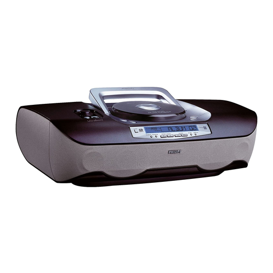
Page 5: Top And Front Panels
CONTROLS ^ & * IR SENSOR Top and front panels MP3-CD/ CD: fast searches backwards, forwards within a track; skips to previous/ next track 1 BASS/ TREBLE – TUNER: tunes radio (manually: down, up); enhances bass/treble response automatic search tuning (down, up) 14 PLAY•PAUSE 2;... -
Page 6: Back Panel
4 SHUFFLE – plays all MP3-CD/ CD tracks in random order 5 BASS – selects ULTRABASS on/off 6 2; – starts MP3-CD/ CD playback – pauses MP3-CD/ CD playback For more information on operation instruction please visit Philips Audio internet site : http://www.audio.philips.com... -
Page 7: Disassembly Diagram
4 - 1 4 - 1 DISASSEMBLY DIAGRAM 3. TO REMOVE VAM2201/03 1. TO REMOVE TOP CABINET ASSEMBLY or remove top cabinet(406) A. Remove screws 3x10 - 6 pcs A. Remove door-battery (433) and cover-bottom (507) B. Remove screws 3x10 - 3 pcs B. -
Page 8: Service Test Program
4 - 2 4 - 2 SERVICE TEST PROGRAM To enter Service * Door switch is ignored → CD door can be opened. Testprogram hold * In CD- and Tuner tests the sound settings Volume up/down, DISPLAY & UB buttons DSC, IS and DBB function as in normal mode, depressed and but flags will not be indicated on the display in all steps. - Page 9 4 - 3 4 - 3 Abbreviations and Pin-description of CD Ics Abbreviations and Pin-description of CD Ics Abbreviations and Pin-description of CD ICs Abbreviations and Pin-description of CD ICs SERVO PROCESSOR SAA7325H SERVO PROCESSOR SAA7325H SYMBOL DESCRIPTION SYMBOL DESCRIPTION HFREF comparator common mode input microcontroller interface R/W and load control line input (4-wire bus mode)
- Page 10 5 - 1 5 - 1 BLOCK DIAGRAM Ultrabass II SOUND IC TDA7468 POWER AMP Source Serial I/O Selector CD99 MP3 MODULE 8 OHM 8 OHM MUTE Treble Bass Speaker Standby 6 OHM 6 OHM Speaker Short circuit ECO6 protection - Speaker TUNER MODULE Mute Mute...
- Page 11 5 - 2 5 - 2 WIRING DIAGRAM Ant. Voltage selector for dual voltage version...
- Page 12 6 - 1 6 - 1 FRONT BOARD - CIRCUIT DIAGRAM FRONT BOARD - CIRCUIT DIAGRAM 1421 B3 3944 I5 1422 B22 3945 I5 1423 G3 3946 J20 1424 H23 3947 J19 1425 G23 3950 J7 2421 K2 3951 J8 2422 M2 3952 K8 2423 M2...
- Page 13 6 - 2 6 - 2 FRONT BOARD - LAYOUT DIAGRAM FRONT BOARD - LAYOUT DIAGRAM (SOLDER SIDE) (COMPONENT SIDE) 2421 D6 2441 C1 2459 C2 3413 C3 3446 D1 3463 C4 3486 B5 3908 C4 3943 A5 4430 B6 5427 A4 7424 B4 2422 C6...
-
Page 14: Front Board
7 - 1 7 - 1 LCD / KEY BOARD - CIRCUIT DIAGRAM LCD / KEY BOARD - CIRCUIT DIAGRAM 1408 K6 1409 K7 1410 L8 1411 K8 1412 K8 1413 L7 1414 L6 1415 L6 1418 L8 LCD / KEY BOARD SHUFFLE MP3CD 1427 H3... - Page 15 7 - 2 7 - 2 LCD / KEY BOARD - LAYOUT DIAGRAM LCD / KEY BOARD - LAYOUT DIAGRAM 4411 3919 2410 3419 3412 3406 3923 3924 3411 3961 3954 3953 3408 3955 3410 4406 3409 2409 4407 3407 3415...
-
Page 16: Tuner Board Circuit Diagram
8 - 1 8 - 1 TUNER BOARD - CIRCUIT DIAGRAM 1105 A1 5121 E11 1121 F14 5122 H5 1122 E14 5123 G5 TUNER BOARD ECO6 / 2101 A3 5130 E6 PORTABLE AUDIO 2103 C7 5131 C6 AM-IF1 VERSION PROGRAMMING COMPONENTS 2104 A3 6103 A3 5111... -
Page 17: Tuner Adjustment Table
8 - 2 8 - 2 TUNER BOARD - LAYOUT DIAGRAM TUNER ADJUSTMENT TABLE ( ECO6 FM/MW- and FM/MW/LW - versions with ferrite antenna) (ECO6 PA) Waverange Input frequency Input Tuned to Adjust Output Scope/Voltmeter 1105 B7 2106 D6 2129 C5 2155 C5 2191 A2 5102 D7... - Page 18 9 - 1 9 - 1 CIRCUIT DIAGRAM - CD99 / MP3 PART 1 CP1 B14 2814 E9 2822 B11 2830 G13 2838 G4 2865 C5 2876 G12 3764 C2 3824 E9 3832 C14 3843 G14 3854 F4 3863 G5 3895 A5 3904 D8 3916 C14...
- Page 19 9 - 2 9 - 2 LAYOUT DIAGRAM - CD99 / MP3 CP1 B3 2810 B14 3838 B15 3933 B15 2811 B14 3839 B15 3934 B15 CP3 B2 2813 C13 3840 B15 3935 B15 1800 E3 2814 C13 3841 B14 3936 B15 1801 A5 2815 C13...
- Page 20 9 - 3 9 - 3 CIRCUIT DIAGRAM - CD99 / MP3 PART 2 1820 C3 2844 A5 2849 C5 2854 D6 3868 A5 3873 B4 3879 C8 3884 D6 3937 E2 7810-A A5 MP864 B9 MP898 C9 MP925 C2 MP934 D9 1821 C10 2845 A5...
- Page 21 9 - 4 9 - 4 LAYOUT DIAGRAM - CD99 / MP3 CP1 B3 2810 B14 3838 B15 3933 B15 2811 B14 3839 B15 3934 B15 CP3 B2 2813 C13 3840 B15 3935 B15 1800 E3 2814 C13 3841 B14 3936 B15 1801 A5 2815 C13...
- Page 22 10 - 1 10 - 1 CIRCUIT DIAGRAM - MP3 DECODER BOARD 2917 E2 2935 A12 3927 C12 3933 F1 5914 C3 1900 C2 2904 I3 2911 G8 2923 F3 2929 B4 3903 C6 3909 C7 3915 D3 3921 G6 3940 A3 3952 A6 3958 D8...
- Page 23 10 - 2 10 - 2 LAYOUT DIAGRAM - MP3 DECODER BOARD DECODER BOARD - LAYOUT DIAGRAM 1901 C13 2900 D12 2901 C12 2903 C12 2905 D13 2936 A1 2937 A2 2938 A2 5908 A1 7906 B3 2906 C13 7906 A14 7907 C14 7910 C13 5908...
- Page 24 11 - 1 11 - 1 CIRCUIT DIAGRAM - AF BOARD (PART 1) 1500 H2 3568 C21 1501 J2 3569 D21 1502 N20 3570 C23 1503 K21 3571 E19 2500 I8 3572 E20 2501 H8 3573 E21 2502 K14 3574 G8 2503 K9 3575 H8 2504 J8...
- Page 25 11 - 2 11 - 2 CIRCUIT DIAGRAM - AF BOARD (PART 2) 0001 B13 5303 I16 0002 C13 6200 C16 0003 C13 6202 I5 1201 A18 6204 A13 1202 D18 6205 J4 3291 6204 3210 1203 B18 6206 J5 PWRDWN 1204 D16 6208 K4...
- Page 26 11 - 3 11 - 3 LAYOUT DIAGRAM - AF BOARD (SOLDER SIDE) 2205 E7 2574 B4 3511 F2 3597 A4 2207 B5 2575 B3 3512 D2 3598 A3 2208 B5 3200 A5 3513 F2 4301 C6 2209 B4 3201 B5 3516 F3 4501 F3 2253 A7...
- Page 27 11 - 4 11 - 4 LAYOUT DIAGRAM - AF BOARD (COMPONENT SIDE) 0001 D2 3202 A2 6252 A2 0002 D2 3211 A4 6257 E4 0003 D2 3212 A4 6301 C4 1201 F2 3250 A1 6302 D4 1202 F3 3253 A2 6304 D4 1203 F2 3254 E4...
-
Page 28: Volume Board
12 - 1 12 - 1 CIRCUIT DIAGRAM - VOLUME BOARD LAYOUT DIAGRAM - VOLUME BOARD VOLOUME BOARD - CIRCUIT DIAGRAM VOLOUME BOARD - LAYOUT DIAGRAM 1400 1402 1404 6401 1401 1403 3404 9400 1400 A2 1403 B6 2401 E4 3403 D4 4408 A3 6411 C5... -
Page 29: Cd Key Board
12 - 2 12 - 2 CD KEY BOARD - CIRCUIT DIAGRAM CIRCUIT DIAGRAM - CD KEY BOARD CIRCUIT DIAGRAM - POWER KEY BOARD POWER KEY BOARD - CIRCUIT DIAGRAM 1416 B3 1417 B4 1419 B2 3416 B3 3417 B4 T482 B2 T483 B2 1405 C5... -
Page 30: Fm Ant Board
12 - 3 12 - 3 CIRCUIT DIAGRAM - FM ANT BOARD CIRCUIT DIAGRAM - HEADPHONE JACK BOARD FM ANT PIN BOARD - CIRCUIT DIAGRAM HEADPHONE BOARD - CIRCUIT DIAGRAM 0250 B4 1250 C2 1251 D4 1303 A2 2300 B4 3300 B3 3302 B4 3337 A3... -
Page 31: Exploded View
13 - 1 13 - 1 EXPLODED VIEW DIAGRAM - CABINET (3x) (1x) (1x) (3x) (1x) (2x) (2x) (3x) (2x) (10x) (3x) (2x) (4x) (3x) (4x) (9x) (3x) (6x) (2x) (4x) (6x) (6x) (3x) (4x) (8x) -
Page 32: Mechanical Partslist
T3 x 12 3140 111 21890 R20 TERMINAL “-" 3140 111 01070 BATTERY SPRING - R20 '+/-' T3 x 16 3140 118 71770 AZ4000 ROD ANTENNA T3 x 20 3139 228 60070 REMOTE CONTROL RC19420002/01 (2x) (2x) T3 x 32 C P/W 2.5 x 10... -
Page 33: Electrical Partslist
14 - 1 ELECTRICAL PARTSLIST - FRONT BOARD - MISCELLANEOUS - - CAPACITORS - 1305 2422 026 05076 3,5 mm PHONE SOCKET 2469 4822 122 33761 22pF 5% NP0 50V 1421 4822 267 11039 Connector 11P 2470 4822 122 31765 100pF 2% NP0 63V 1422 4822 265 11184... - Page 34 14 - 2 ELECTRICAL PARTSLIST - FRONT BOARD - RESISTORS - - RESISTORS - 3460 4822 051 30102 1K 5% 0,062W 3941 4822 051 30471 470R 5% 0,062W 3461 4822 051 30103 10K 5% 0,062W 3942 4822 051 30471 470R 5% 0,062W 3462 4822 051 30102 1K 5% 0,062W...
- Page 35 14 - 3 ELECTRICAL PARTSLIST - FRONT BOARD - COILS & FILTERS - 5426 4822 242 11033 CRYSTAL 4,332MHz 5427 2422 549 44393 IND FXD 2,7K 100MHz 5428 2422 549 44393 IND FXD 2,7K 100MHz 5429 2422 549 44393 IND FXD 2,7K 100MHz 5430 2422 549 44393 IND FXD 2,7K 100MHz...
- Page 36 14 - 4 ELECTRICAL PARTSLIST - LCD BOARD - MISCELLANEOUS - - RESISTORS - 3140 118 50990 BACKLIGHT ASSY BLUE 3417 4822 051 30103 10K 5% 0,062W 1400 4822 265 11208 CONNECTOR 10P 3418 4822 116 52175 100R 5% 0,5W 1401 2422 129 16349 ROT ENCODER 24P...
- Page 37 14 - 5 ELECTRICAL PARTSLIST - TUNER BOARD - MISCELLANEOUS - - CAPACITORS - 1121 4822 267 10733 Connector 4P 2165 4822 126 13838 100nF 80/20% Y5V 50V 1122 4822 267 10954 Connector 5P 2166 5322 122 31647 1nF 10% X7R 63V 2167 4822 122 33926 12pF 1% 50V...
- Page 38 14 - 6 ELECTRICAL PARTSLIST - TUNER BOARD - RESISTORS - - TRANSISTORS & IC - 3176 4822 051 20333 33K 5% 0,1W 7101 4822 209 90924 TEA5757H/V1 3180 4822 117 10833 10K 1% 0,1W 7102 4822 130 42131 BF550 3186 4822 117 11448 180R 1% 0,1W...
- Page 39 14 - 7 ELECTRICAL PARTSLIST - CD99/MP3 BOARD - MISCELLANEOUS - - CAPACITORS - 1011 3140 118 82770 PBAS MP3 DECODER 2857 4822 124 41751 47µF 20% 50V 1800 4822 265 10925 FFC CONNECTOR 15P 2860 4822 126 14508 180pF 5% 50V NP0 1823 4822 265 11207 FFC CONNECTOR 6P...
- Page 40 14 - 8 ELECTRICAL PARTSLIST - CD99/MP3 BOARD - RESISTORS - - RESISTORS - 3843 4822 051 30102 1K 5% 0,062W 3907 4822 117 13608 4,7R 5% 0,0016W 3844 4822 051 30101 100R 5% 0,062W 3910 4822 051 30103 10K 5% 0,062W 3846 4822 051 20223 22K 5% 0,1W...
- Page 41 14 - 9 ELECTRICAL PARTSLIST - CD99/MP3 BOARD - COILS & FILTERS - 1810 2422 543 01068 CRYSTAL 8,4672MHZ 5803 4822 157 11231 1µH 10% 5804 4822 157 11074 100µH 5805 4822 157 11074 100µH 5806 4822 157 11074 100µH 5807 4822 157 11074 100µH...
- Page 42 14 - 10 ELECTRICAL PARTSLIST - MP3 DECODER BOARD - CAPACITORS - - RESISTORS - 2900 4822 124 23002 10µF 20% 16V 3916 4822 051 30339 33R 5% 0,062W 2901 4822 124 12095 100µF 20% 16V 3917 4822 051 30102 1K 5% 0,062W 2903 4822 124 80151...
- Page 43 14 - 11 ELECTRICAL PARTSLIST - MP3 DECODER BOARD - COILS & FILTERS - 5911 4822 157 11074 100µH 5912 4822 157 11074 100µH 5913 4822 157 11074 100µH 5914 4822 157 11074 100µH - IC & TRANSISTORS - 7900 9352 629 68135 TDA3663/N1 7901...
- Page 44 14 - 12 ELECTRICAL PARTSLIST - AF BOARD - MISCELLANEOUS - - CAPACITORS - 1203 4822 071 53152 FUSE 3,15A 2507 4822 126 13881 470pF 5% 50V 1204 4822 071 53152 FUSE 3,15A 2508 3198 017 41050 1 F 10% Y5V 10V 1500 4822 267 10731 CONNECTOR 6P...
- Page 45 14 - 13 ELECTRICAL PARTSLIST - AF BOARD - RESISTORS - - RESISTORS - 3200 4822 051 30333 33K 5% 0,062W 3314 4822 117 13613 2,2R 5% 0603 3201 4822 051 30333 33K 5% 0,062W 3315 4822 117 13613 2,2R 5% 0603 3202 4822 116 83883 470R 5% 0,5W...
- Page 46 14 - 14 ELECTRICAL PARTSLIST - AF BOARD - RESISTORS - - RESISTORS - 3540 4822 051 30103 10K 5% 0,062W 3594 4822 051 30102 1K 5% 0,062W 3541 4822 117 12902 8,2K 5% 0,062W 3595 4822 051 30101 100R 5% 0,062W 3542 4822 051 30153 15K 5% 0,062W...
- Page 47 14 - 15 ELECTRICAL PARTSLIST - AF BOARD ELECTRICAL PARTSLIST - MISCELLANEOUS - DIODES - - MISCELLANEOUS - 6502 4822 130 30621 1N4148 1001 2422 030 00333 AC SOCKET (VDE) 6503 4822 130 30621 1N4148 1001 4822 265 20706 AC SOCKET (UL) 6504 4822 130 83757 BAS216...
Need help?
Do you have a question about the AZ4000 and is the answer not in the manual?
Questions and answers