
Summary of Contents for Econ OP320
- Page 1 ECON Operator Panels Operation manual Control Solutions Group 'Simple solutions to difficult problems' Page 1 of 86 Pages...
-
Page 2: Table Of Contents
Chapter 1 Summary of the products..........4 1-1 Function ........................4 1-2 General specification....................5 1-3 Product types......................6 1-4 Each part’s name ...................... 7 1-4-1 OP320/OP320-S ................... 7 1-4-2 OP320-A/OP320-A-S ................. 10 1-5 Interface definition and connection diagram............. 14 1-5-1 OP320 ......................14 1-5-2 OP320-S...................... - Page 3 Chapter 3 Operation methods of OP320 ........56 3-1 Online communication ................... 56 3-2 Shift the screen....................... 56 3-3 System’s password ....................57 3-4 Modify the data ...................... 59 3-5 Switch value operating ............59 Chapter 4 New addition function of OP520 ..............60 4-1-2 Screen jump function.....................
-
Page 4: Chapter 1 Summary Of The Products
Chapter 1 Summary of the products 1-1 Function The OP series is a mini human machine interface The OP320 display has the following: The communication port is RS232/RS422 Seven keys can be defined as function keys, and they can substitute some machine keys on the control table ... -
Page 5: General Specification
There are 16 button lamps on the panel, which can be used to status PLC’s status The communication format is RS232/RS422/RS485 LCD display with backlight STN. The resolution is 320×240. It can display 40 characters × 15 lines. 1-2 General specification 1. -
Page 6: Product Types
1-3 Product types Products classification OP series OP320 OP320-S OP320-A OP320-A-S OP520 The number of keys Size 3.7” 5.7” screen CCFL background lamps display Monochrome color Communication RS232/ RS232/ RS232/ RS232/ RS232/RS422/ port RS422 RS485 RS422 RS485 RS485 Shape and size 163.5W×101.7H×50.4D... -
Page 7: Each Part's Name
1-4 Naming 1-4-1 OP320/OP320-S The OP320(OP320-S), has the LCD display window, and 7 user buttons, The seven buttons can be set to be special function keys, screen jump or on-off set and other functions. Page 7 of 86 Pages... - Page 8 Button Basic function(These keys are not used as function keys) Normally sets the main menu or the screen which is used most often to be the system’s initial screen. When modifying the register’s data, shift the modified data bit to the left. When modifying the register’s data, shift the modified data bit to the right.
- Page 9 At the back of OP320 (OP320-S), there are power terminals , communication socket and contrast adjusting potentiometer. OP320 display has backlight auto turn off if there is no operation for three minutes. Page 9 of 86 Pages...
-
Page 10: Op320-A/Op320-A-S
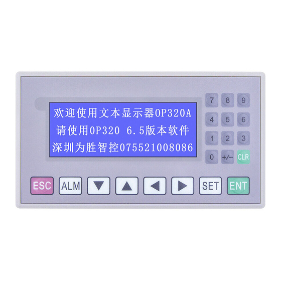
1-4-2 OP320-A/OP320-A-S On the face of OP320-A (OP320-A-S), there is not only LCD display but also 20 buttons for user special function. Refer to OP520 for detail button definition. + / - SET ENT Page 10 of 86 Pages... - Page 11 Table of keys’ basic function: Basic function Escape to the system’s initial screen is appointed by the user when designing the screen It can also be used as a function key. It is used as a function key. It is used as a function key. It is used as a function key.
- Page 12 1-4-2 OP520 On the front of OP520, there are not only LCD display window, but also 42 film buttons. Number display keyboard area + /- Direction Free define multi-function keys which can extract insert card(16 in total) Page 12 of 86 Pages...
- Page 13 Button’s basic function table Button Basic function Escape to the system’s initial screen is appointed by the user when designing the screen It can also be used as a function key. When modifying the register’s data, shift the modified data bit to the left. When modifying the register’s data, shift the modified data bit to the right.
-
Page 14: Interface Definition And Connection Diagram
OP520 with any series of PLC with the communication cable, and you can also download using the same communication between the OP520 or the PLC. 1-5 Interface definition and connection diagram 1-5-1 OP320 Serial pin out for the OP320. Pin ID definition OP-SYS-CAB connecting diagram Page 14 of 86 Pages... -
Page 15: Op320-S
OP side(9PIN plug) OP-SYS-CAB connecting diagram:(V4.0) : OP side(9PIN plug) computer side (9PIN plug) 1-5-2 OP320-S Serial port pin’s definition ID number for the OP320-S. Pin ID Definition Page 15 of 86 Pages... -
Page 16: Op320-A
OP-SYS-CAB connecting diagram: OP side(9PIN plug) computer side(9PIN plug) OP-SYS-CAB connecting diagram:(V4.0) : OP side(9PIN plug) computer side(9PIN plug) 1-5-3 OP320-A Serial port pin’s definition ID number of the OP320-A. Pin ID Definition Page 16 of 86 Pages... -
Page 17: Op320-A-S
OP-SYS-CAB connecting diagram: OP side(9PIN plug) computer(9PIN plug) diagram:(V4.0) : OP-SYS-CAB connecting OP side(9PIN plug) computer(9PIN plug) 1-5-4 OP320-A-S Serial pin’s definition ID number of OP320-A. Pin ID Definition Page 17 of 86 Pages... - Page 18 OP-SYS-CAB connecting diagram: OP side(9PIN plug) computer(9PIN plug) OP-SYS-CAB connecting diagram:(V4.0) : OP side(9PIN plug) computer(9PIN plug) 1-5-5 OP520 Serial port pin’s definition ID number of the OP520. PORT1 (download port): Pin’s ID Definition Page 18 of 86 Pages...
-
Page 19: Sizes And Installing Methods
PORT2 (communication port): Pin’s ID Definition Empty 空 OP-SYS-CAB connecting diagram: DP210(9PIN female) Computer(9PIN female) 1-6 Installing methods OP320 (OP320-S) The product’s actual size is : 155.5×92.7×50.4 (in mm) The cutout size is: 156.5×94 (in mm) Page 19 of 86 Pages... - Page 20 OP320 –A (OP320-A-S) The product’s actual size is: 162.2×84.2×30 (in mm) The cutout size is: 163.2×85.2 (in mm) OP520 The product’s actual size is: 284×194×50 (in mm) The cutout size is: 269.2×156.4 (in mm) Page 20 of 86 Pages...
-
Page 21: Chapter 2 Editor Software Op20
Chapter 2 OP20 Software 2-1 Basic summary of the OP20 OP20 develops software for character display for the OP series application screen. It runs on WINDOWS 98/2000/XP system. 2-1-1 Project screens The project’s basic element is the screens. 2-1-2 Screen content You can place Characters, lamps, switches, data display set windows, and next screen keys and other element in each screen. -
Page 22: The Use Flow Of Op20
2-1-3 The use flow of OP20 The basic use flow for an OP20 program: Set up the software. Run the program. Create or open a project Create or open a screen Edit the screen. Save the project Transfer the screen. Page 22 of 86 Pages... -
Page 23: Edit The User's Screen
2-2 Editing the user’s screen 2-2-1 Create a project After running the OP20 Software, There will be a screen editor in the center of the computer’s display. Screen Display all the screen’s serial number in the project. Description Description of the screen function ... - Page 24 ] button to return back to this screen. Log in the alarm list information, each piece of alarm information corresponds with an internal relay. Via RS232 port of the computer, download the completed project file to OP320 display. Page 24 of 86 Pages...
-
Page 25: Make A Basic Screen
PLC type Select the PLC’s type so when the OP20 is downloaded the screen, will transfer the appoint PLC’s communication protocol along with the screen data to the display. 2-2-2 Make a basic screen The following we will take Mitsubishi FX series PLC as the example to describe: First, enter the edit status of the system’s initial screen (If default it will be the No.1 screen). -
Page 26: The System Parameter Of Op20
Sample analog quantity data OP320 can connect with a 8-channel analog value sample module or an 8-channel temperature sample module via the RS485 communication port. The register’s head address which the analog quantity is auto stored is assigned by this parameter. - Page 27 Indication lamp, displays the on-off status of internal relay. Function key, all the seven keys in the bottom of OP320 can be defined as function keys. Create a real time trend . Bar is used to display analog quantities parameter intuitively, such as...
-
Page 28: Function Key (Screen Jump)
Coordinate The X value statuss this text’s horizontal position The Y value statuss this text’s vertical position The coordinate origin point is in the left top of the screen. Special Double: Display the characters multiply in horizontal and vertical. Inverse: The color of the message and the background displays inversely. - Page 29 In the pull down menu of “key”, select the appropriate key from seven keys. Hand In order that the operator can operate it correctly and quickly, add a hand diagram in front of the button. Encrypt This function key is only valid when the system’s password has been opened. ...
- Page 30 Select a key in the pull-down menu of “key”, there are seven keys Page 30 of 86 Pages...
- Page 31 After setting the function key, place text “set parameter” to the right of the button diagram to prompt the operator. Click “<” key to enter parameter. You can set the NO.20 screen to be the state set screen. Page 31 of 86 Pages...
- Page 32 In the main menu screen, add an alarm screen jump key. You can jump to the alarm list screen, refer to the alarm information. For the alarm information, you can refer to 2-2-14 Page 32 of 86 Pages...
-
Page 33: Data Display Window
2-2-6 Data display window Setting methods of parameter display windows and parameter set windows in detail. Also, how to set the password. E.g. The NO.10 screen can monitor and set three groups of parameters, with the production of Class A, Class B, Class C. The row in the left is the current value, the row in the right is the target value. - Page 34 Set the screen No. to be 10, enter the screen description “set parameter”. Click [OK] button to confirm. After that, there will be the content of screen attribute in the right bottom of the screen. Set the “Previous Screen No.” to be 0, set the “Next screen No.” to be 20.
- Page 35 Click the button, there will be a rectangle dashed frame moves with the mouse, move it to normal position, then click on the left button of mouse to confirm it. Display “12345” these five numbers inside the dashed frame, that means that this element is a register display window or register set window whose length is five bits.
- Page 36 Decimal system Display the data in the register in decimal format Signed Select this normalty only when the display data in decimal format, if the highest bit of the register is 1, then display the data in negative. e.g. FFFEH equals –2. ...
-
Page 37: Data Set Window
2-2-7 Data set window Click button, there will be a rectangle dashed frame which moves with the mouse in the screen..Click on the left key of mouse to confirm. In the register column, select “set”, the monitor function, the element also has a set function. Page 37 of 86 Pages... - Page 38 After the frame “Set” been selected, add another two options : “Encrypt” and “upper/lower limitation”. Encrypt: All parameters can be protected by a password. The methods of setting and modifying the password is as follows: Pick “tool” “set OP20” command, there will be a dialog box: set OP series: Input the password or modify the original password, e.g.
-
Page 39: Status Lamps
Upper/lower limit: can be set. This will limit an input too large or too small. E.g. set the upper limit to be 9000, the lower limit to be 0. Only when 0< the set value<9000 can the set value be written into the PLC. 2-2-8 Indication lamps How to make a mode set screen. - Page 40 Click the [new] button, and pop up a dialog box of “New Screen”. Set the screen’s No. to be 20, and type “set mode” in the description. Click [OK] button to confirm. Then there will be the screen’s normalty display. Page 40 of 86 Pages...
- Page 41 Click button to place the status lamp, there will be a rectangle dashed frame that moves with the mouse. Click the left key of the mouse to confirm. Coil No. The define ID No. of the internal relay of the PLC. ...
- Page 42 Set the coil’s No. to be M10, select the square lamp; positive logic. Then in the window there will be a vacant square status lamp. Click the button to lay the function key, there will be a rectangle dashed frame which moves with the mouse, then move it to the normal position and click on the left key of mouse to confirm it.
- Page 43 In the function column, select the “SET” button to be the auto mode setting button. Set the coil’s definition No. to be M10, and set the action mode to be ON.. Place text “automatic” to the right of the button., it means that this button’s function is select automatic mode.
- Page 44 Set the manual button and the manual status lamp with the same method. The address of the lamp is still M10. Select the display normalty negative logic. The button is “ENT” button, the button’s function is to set M10 relay OFF. Set two circle lamps, positive logic.
-
Page 45: Function Key (Switch Quantity Operation)
2-2-9 Function key (switch quantity operation) Click button to place the function key, select “>” button, the correspond address is M20, its function is momentary set M20 relay to be ON, and keep the hand diagram. It statuss that when you click on the “>” button, M20 of PLC is set to be ON, and the motor begins to run forward. -
Page 46: Trenddiagram
2-2-10 Single line Trend In the process industry, the value of some parameters change slowly. The operator wants to know these parameters’ change process in a certain time. The trend diagram is the best way to display these values. Click the button, there will be a rectangle dashed frame moving with the mouse. -
Page 47: Bar Diagram
2-2-11 Bar graph Click the button, there will be a rectangle dashed frame that moves with the mouse. Move to the normal position and click the left key of the mouse to confirm. Register No. The register’s address corresponds with the bar graph. ... -
Page 48: Diagram Display
This bar monitors the value in D300. When the bar displays in the full scale, it statuss that the value in D100 is 100; when the bar displays in 50% scale, it statuss that the value in D300 is 50. 2-2-12 Diagram display Insert a bitmap file, which can display the machine’s picture and makes it easy for the operator to understand. -
Page 49: Dynamic Messages
Note: it can display a bitmap with 192×64 pixels at most. The extra part will be removed automatically. 2-2-13 Dynamic messages You can display the current machine’s status via words which makes the operators job easier, and will improve the monitoring efficiency. The dynamic message is your best choice. Click the button, there will be a rectangle dashed frame that moves with the mouse. - Page 50 In the screen’s edit area, there are some initial words “dynamic message” and the following normalties in the dialog box. Register No. The register’s No. of the PLC. Decimal Value format. HEX/BCD Display the data in hex system. ...
- Page 51 E.g. Input “No.1 motor runs forward” in the first line, input “No.1 motor runs in reverse” in the second line, input “No.1 motor stops” in the third line. The dynamic message responds to data in D200. If data in D200 hasn’t been set, then the text frame has no display, if data in D200 is 0, then display “No.1 motor clockwise”.
-
Page 52: Alarm List
When any of the internal relay turns to ON from OFF, that means that when there is an alarm, the OP320 will automatically pop up the alarm display screen, then displays the alarm information in the first line. - Page 53 Input other information in the same way. After all the alarm information been input, change the coil’s No. to be M100 (example), i.e. it statuss that M100 to M106 i corresponds with the 7 alarms. ndividually The operator can immediately react to solve the problem. If you want to return back to the monitor screen, just click [ ] button.
-
Page 54: Save A Project
Input the file name, select the right path, then press “save” button to save it. 2-4 Downloading the screen Connect the computer’s 9 pin RS232 port and the 9 pin port of OP320 with the download cable. Make sure that OP320 is powered. Click the button to begin downloading the data. - Page 55 Turn off the display’s power. Pull out the screen’s transfer cable OP-SYS-CAB0, connect the OP320 and PLC with the PLC communication cable.There will be “communicating” in the right bottom of the display, that means OP320 is communicating with PLC. Page 55 of 86 Pages...
-
Page 56: Chapter 3 Operation Methods Of Op320
Chapter 3 OP320 Operation methods 3-1 Online communication Note: No matter if the PLC is running or programming, the OP320 will operate normally. 3-2 Shift the screen OP320 will first display the NO.1 screen. (Because the system’s initial screen is No.1 screen.) -
Page 57: System's Password
3-3 System’s password Before modifying the data, you should first open the system’s password. Press the password select key, and type the password. Click the button to enter the password screen, the screen displays the following: Select 1, execute the operation of opening password; select 2, to close the password. Click on the button, returning back to the monitor status. - Page 58 Select 1, the screen displays: Click the “∧” button or “∨”button to input the password’s value, and click the “ENT” button to confirm. If the password value is correct, the screen displays: If the password value is in error, the screen displays: Select 2 , close the password, the screen displays: Page 58 of 86 Pages...
-
Page 59: Modify The Data
3-4 Modifying the data value If the password has been entered, click the “ENT” button. The production set value of class A will high light, which means you can set class A’s production value. Click the “∧” button and “∨” button to modify the value, click on the “<” and “>” to set the digit’s position, the data range is 0 to 9. -
Page 60: Chapter 4 New Addition Function Of Op520
Chapter 4 New additional functions of the OP520 4-1 Setting general function key When editing the project screen of the OP520, press the key, there will be a dialog box for you to set the general function key. The dialog box displays 20 function keys (K1~K10,F1~F10), If the function key is not set, it means that this key can only be used as the normal function key. - Page 61 ★ Force ON When the key is pressed down, set the coil ON. ★ Force OFF When the key is pressed down, set the coil OFF. ★ Reverse When the key is pressed down, set the coil in reverse. ★ Momentary ON When the key is pressed down, set the coil ON, when the key pops up, the coil will be set OFF.
-
Page 62: Screen Jump Function
4-1-2 Screen jump function In the “Set General Function Key” dialog box, set function key K1 to make it have the function of screen jump. The dialog box will display screen jump select: ★ Screen The screen will jump to one which has the number in the number select frame as the screen No. -
Page 63: Advanced Function
Set the encryption Select the encryption check box, then the key will have the function of the password protection. 4-1-3 Advanced functions In the dialog box “Set Global Function Key”, select the advanced functions for K1.The dialog box will display advanced function option: ★... -
Page 64: Status Status Lamp
4-2 Status lamps There are 16 button status lamps in the left bottom of OP520, they can display the register’s data, it will reflect the machine’s work status. Press the key, open the system setting. Select the display function for the status lamp. The 16 button status lamps are each controlled by Bit0-Bit10 of D0 register. -
Page 65: Application Examples Of Global Function Key And Button Status Lamp
4-3 Application examples of global function keys and button status lamps In the following example, we will start/stop the motor with the global function key. And use the panel status lamp to monitor the ON/OFF status. Create a new project, in the displays selected dialog box, select OP520. Select Mitsubishi in the PLC selection dialog box and press the key. - Page 66 Single click 《Set OP Series》 Select 《Light Panel Status LED》check box, the corresponding word address of the 16 status lamps is D0. Program the Plc with the following action: If M0=1 Then SET Y0 RST Y1 D0=H0080 If M1=1 Then RST Y0 SET Y1 D0=H8000 Page 66 of 86 Pages...
-
Page 67: Inside Clock (Optional)
4-4 internal clock (optional) To set the clock, click the button, or click “Tool” -> “Set OP Series” command, there will be a OP20 system parameter setting dialog box: Select “Use Data/Time Module”, and set the control register’s No. if you use. E.g. D46, then the clock’s data will be placed into three groups of registers which start with D46. -
Page 68: Chapter 5 Application Examples Of Op520
Chapter 5 Application examples of the OP520 5-1 Examples In the following example we will take our company’s EC series PLC to make a project. Page 68 of 86 Pages... - Page 69 Page 69 of 86 Pages...
-
Page 70: Make A Screen
Open the OP20 screen set tool and create a new project, selected dialog box from the program. Select OP520 and click OK. There will pop up a PLC selection dialog box. In the pull down menu, select econ EC series and click OK. Then you can start screen edit. -
Page 71: Chapter 6 Op320-S, Op320-A
OP320-A/OP320-A-S is a cut down version of OP520, you can refer to OP520 for its use, but there is no global set function keys, you can refer to OP320 for its use and refer to OP520 for its number keys’. -
Page 72: Chapter 7 Plc's Connection Method
Chapter 7 PLC’s connection method 7-1 Econ EC series PLC OP series can communicate with econ EC series PLC, the communication port is the PLC’s program port. Item Content OP320 communication port 9 pin communication port PLC communication port Program port... -
Page 73: Mitsubishi Fx Series Plc
OP series can communicate with all FX series of Mitsubishi at present. The communication port is PLC program port or FX2N-422BD module of the FX2N series PLC. Item Content OP320 communication port 9 pin communication port PLC communication port Program port or FX2N-422BD... -
Page 74: Siemens S7-200 Series Plc
9 RD+ 7 TD+ 5 GND 3 GND Note: it is normal for OP320, OP320-A, OP520. 7-3 Siemens S7-200 series PLC OP series can communicate with the program port or extension port of S7-200 series PLC via PPI protocol. Item... - Page 75 The connection diagram of OP-S7-CAB0 OP side PLC side 9 plug (9PIN) Note: it is normal for OP320-S, OP320-A-S, OP520. Page 75 of 86 Pages...
-
Page 76: Omron C Series Plc
7-4 Omron C series PLC CPM1A, CQM1-CPU11 has only one communication port. In order to communicate with the OP320, it needs the communication cable CIF01-CAB produced by our company to transfer the program port’s signal to RS232 signal. Item Content... -
Page 77: Koyo S Series Plc
7-5 Koyo S series PLC When OP series communicates with SZ-4, OP320 can connect with not only Port1 but also Port2. Item Content OP320 communication port 9 pin communication port PLC communication port Program port or extension port default communication... - Page 78 The connection diagram of OP-SU-CAB0 2 RXD 2 TXD OP side 3 TXD 3 RXD PLC side (9PIN 4 RTS (25PIN) plug) 5 CTS 5 GND 7 GND Note: it is normal for all OP series models. Page 78 of 86 Pages...
-
Page 79: Schneider Neza Series Plc
7-6 Schneider NEZA series PLC The OP series can communicate with the NEZA series PLC via MODBUS protocol. Item Content OP320 communication port RS485 communication port PLC communication port Program port default communication 9600 bps, 8 bit, 1 stop, Even... -
Page 80: Delta Dvp Series Plc
The connection diagram of OP-NEZA-CAB0 OP side PLC side (9pin (9PIN) plug) Note: it is normal for OP320-S, OP320-A-S, OP520. 7-7 DELTA DVP series PLC OP series can communicate with DVP series PLC, the communication port is PLC program port. Item Content... -
Page 81: Lg Master-K Series Plc
Note: it is normal for all OP series models. 7-8 LG Master-K series PLC The OP series can communicate with LG Master-K series PLC, the communication port is port 2. Item Content OP320 communication port 9 pin communication port PLC communication port Port2 default communication... -
Page 82: Matsushita Fp Series Plc
5 GND 5 GND Note: it is normal for all OP series product. 7-9 Matsushita FP series PLC The OP320 can communicate with Matsushita FP series PLC, the communication port is PLC program port or extension port. Item Content OP320 communication port... - Page 83 The connection diagram of OP-FP-CAB0 2 RXD 2 TXD OP side 3 TXD 3 RXD PLC side (9PIN) (9PIN) 5 GND 7 GND Note: it is normal for all OP series models Page 83 of 86 Pages...
-
Page 84: Facon Fb Series Plc
7-10 FACON FB series PLC The OP320 can communicate with FACON FB series PLC, the communication port is PLC program port or extension port. Item Content OP320 communication port 9 pin communication port PLC communication port Program port or extension port... - Page 85 The connection diagram of OP-FB-CAB0 1 RXD1 2 RXD 2 TXD1 OP side 3 TXD PLC side (9PIN) (15PIN) 5 GND 6 GND 3 RTS1 4 CTS1 Note: it is normal for all OP series models Page 85 of 86 Pages...
- Page 86 ECON From Control Solutions Group 'Simple solutions to difficult problems' www.controlsolutionsgroup.eu E-mail support@controlsolutionsgroup.eu Please consider the environment before printing this document Page 86 of 86 Pages...
Need help?
Do you have a question about the OP320 and is the answer not in the manual?
Questions and answers