
Summary of Contents for Nidek Medical LEX-DRILL
- Page 1 AUTO DRILLING UNIT Model SERVICE MANUAL December 2007 Pages in total: 94 LHM2A*RDA001A/E...
- Page 2 NIDEK CO., LTD. : 34-14, Maehama, Hiroishi-cho, Gamagori, Aichi 443-0038, Japan (Manufacturer) Telephone: (81-533) 67-6611 Facsimile: (81-533) 67-6610 NIDEK CO., LTD : 3F Sumitomo Fudosan Hongo Bldg., 3-22-5, Hongo, (Tokyo Office) Bunkyo-Ku, Tokyo 113-0033, Japan Telephone: (81-3) 5844-2641 Facsimile: (81-3) 5844-2642 NIDEK INCORPORATED : 47651 Westinghouse Drive, Fremont, California 94539, U.
-
Page 3: Table Of Contents
Table of Contents § 1 INTRODUCTION ................1-1 § 2 SAFETY PRECAUTIONS..............2-1 § 3 PRODUCT OUTLINE ............... 3-1 3.1 Quality Standard...................... 3-1 3.2 Configuration ......................3-2 3.3 Labels ........................3-5 3.4 Assembly Component Layout ................. 3-8 3.5 Electrical Component Layout .................. 3-9 3.6 Replacement Parts .................... - Page 4 6.21 Rocker Switch ..................... 6-12 6.22 Fuse Holder and Connector RS-232C ............... 6-12 6.23 Fan ........................6-12 6.24 H Axis Sensor ...................... 6-13 6.25 S Axis Sensor ...................... 6-13 6.26 V Axis Sensor ...................... 6-14 6.27 θ Axis Sensor ...................... 6-14 6.28 Chuck SW Sensor ....................
- Page 5 8.6 Jigs ........................8-17 8.7 Tools ........................8-18 8.8 Consumables ......................8-18...
- Page 6 [This page is intentionally left blank.]...
-
Page 7: Introduction
LHM2A*RDA001A/E § 1 INTRODUCTION • This service manual is for the NIDEK AUTO DRILLING UNIT, Lex Drill. • For correct service, thorough understanding of the contents of this manual is required prior to the service. • This manual mainly describes simple measures by part replacement. •... - Page 8 LHM2A*RDA001A/E [This page is intentionally left blank.] 1 - 2...
-
Page 9: Safety Precautions
LHM2A*RDA001A/E § 2 SAFETY PRECAUTIONS <General precautions> • Servicing must be performed by NIDEK service persons or other qualified personnel. • Perform all servicing according to the procedures described in this manual. Failure to do so may cause unexpected accident or malfunction. •... - Page 10 LHM2A*RDA001A/E [This page is intentionally left blank.] 2 - 2...
-
Page 11: Product Outline
LHM2A*RDA001A/E § 3 PRODUCT OUTLINE 3.1 Quality Standard Classi- Item Measurement method/tool Acceptance criteria fication Main body 1 unit <Accessories> Drill bit 5 units Cup holder 1 unit (built-in) Lens chuck 1 unit (built-in) Visually check the contents Product unit and numbers. -
Page 12: Configuration
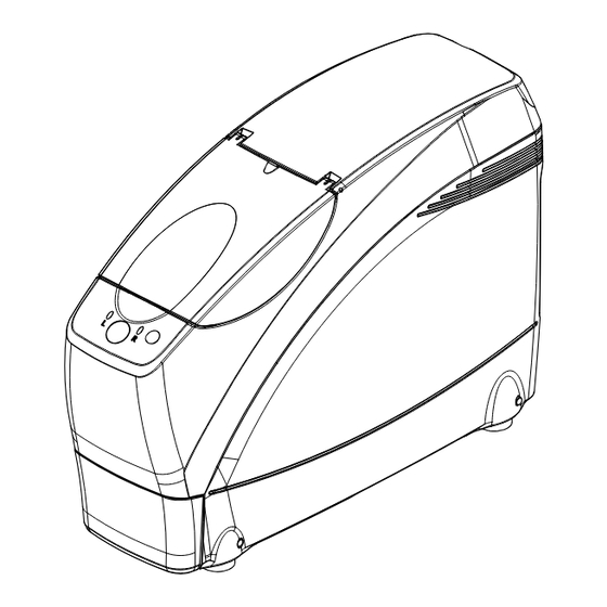
LHM2A*RDA001A/E 3.2 Configuration Rear view Front view 1. Lid LED (left side) Power switch LED (right side) Vent holes 2. Drill release button 5. STOP button 4. START button 6. Inlet 7. Edger port 3. Waste bin 1. Lid The door of the processing chamber It prevents processing waste from flying free. - Page 13 LHM2A*RDA001A/E Processing chamber 8. Lens chuck 9. Cup holder 10. Drill 11. Spindle 8. Lens chuck Presses againat a lens set in the cup holder to secure it. 9. Cup holder This part holds a lens blocked with a pliable cup.
- Page 14 LHM2A*RDA001A/E (Lex 1000 Control panel) 7. Frame button 9. Polish button 10. FC button 6. Lens button 8. Mode button 11. R/L button button 7. Frame button Switches the screen between the layout and Used to select processing mode. menu. Extended pressing of this button switches button, button...
-
Page 15: Labels
LHM2A*RDA001A/E 3.3 Labels Indicates that caution must be taken. Refer to the operator’s manual before use. Indicates that the instrument must be supplied only with alternating current. Fuse. Indicates the date of manufacture. Indicates the manufacturer. Indicates that the state of the power switch. When the symbol side of the switch is pressed down, the power is on. - Page 16 LHM2A*RDA001A/E Front view Rear view 3 - 6...
- Page 17 LHM2A*RDA001A/E Top view Processing chamber l u f h t i t t a e l c s i n 3 - 7...
-
Page 18: Assembly Component Layout
LHM2A*RDA001A/E 3.4 Assembly Component Layout 44101 44101 -2100 -1100 44101 -5200 44101 44101 -5300 -5200 44101 -5300 44101 44101 -3000 -5110 44101 -5100 44101 -5130 44101 44101 -5140 -5120 44101-5000 PART NO. DESCRIPTION 44101-1100 電源部AS POWER SUPPLY ASSY 44101-2100 トップカバーAS TOP COVER ASSY 44101-3000 加工部AS ... -
Page 19: Electrical Component Layout
LHM2A*RDA001A/E 3.5 Electrical Component Layout BA02 CA23 CA10 CA04 BA01 CA07 CA11 SYM. PART NO. DESCRIPTION BA01 44101-BA01 MAIN基板 MAIN BOARD BA02 44101-BA02 キャリッジ中継基板 CARRIGE RELAY BOARD CA04 44101-CA04 コネクター(RS-232C) CONNECTOR(RS-232C) CA07 44101-CA07 H軸センサー H AXIS ORIGIN SENSOR CA10 44101-CA10 V軸センサー... - Page 20 LHM2A*RDA001A/E CA13 CA12 BA03 CA08 41971 -CA07 SYM. PART NO. DESCRIPTION BA03 44101-BA03 SW PANEL 基板 SW PANEL BOARD CA07 41971-CA07 ファン CA08 44101-CA08 S軸センサー S AXIS ORIGIN SENSOR CA12 44101-CA12 チャック SW センサー CHUCK ORIGIN SW SENSOR CA13 44101-CA13 チャックセンサー...
-
Page 21: Replacement Parts
LHM2A*RDA001A/E 3.6 Replacement Parts : Need adjustment after replacement, : Need confirmation after replacement 3 - 11... - Page 22 LHM2A*RDA001A 3 - 12...
-
Page 23: Troubleshooting
LHM2A*RDA001A/E § 4 TROUBLESHOOTING 4 - 1... - Page 24 LHM2A*RDA001A/E 4 - 2...
-
Page 25: Removing Procedures
LHM2A*RDA001A/E § 5 REMOVING PROCEDURES 5.1 Prior to Removal Work Be sure to remove the drill bit (44101-M381) for safety before removing covers and replacing parts. 1. The assembly procedure after replacing parts is generally not described as it is basically the reverse of the disasssembly procedure. -
Page 26: Covers
LHM2A*RDA001A/E 5.3 Covers * Turn off the power switch and disconnect the power cord. 1. Right cover (44101-M202) and left cover (44101-M203) Unscrew SB4 × 6 (n = 2 for each) to remove the right cover (44101-M202) and left cover (44101-M203). -
Page 27: Replacement Procedures
LHM2A*RDA001A/E § 6 REPLACEMENT PROCEDURES Be sure to remove the drill bit (44101-M381) for safety before removing covers and replacing parts. Calibration and processing adjustment 1) When mechanical part position is changed after part replacement or mechanical adjustment, be sure to perform calibration of the shading plate position (see 7.4.1) and processing adjustment (see 7.5). -
Page 28: Processing Unit Assy
LHM2A*RDA001A/E 6.2 Processing Unit ASSY. Replacement part: Processing unit ASSY. (44101-3000) 1. Remove the right cover (44101-M202), left cover (44101-M203), top cover ASSY. (44101- 2100), washer (44101-M206), protect plate (44101-M104), cover (44101-M103), waste bin (44101-M205), and dustproof plate (44101- M102) (see 5.3). 2. -
Page 29: Chuck Arm Assy
LHM2A*RDA001A/E 3. Pull out the drill motor from the motor cover. 4. Loosen HH4 × 6 (n = 2) to remove the drill motor. 5. Reassemble the parts in reverse order. 1) Check rattle adjustment of the S axis (see 7.3.2). 2) Calibration of the shading plate position HH4×6 is necessary (see 7.4.1). -
Page 30: Carriage Assy
LHM2A*RDA001A/E 6.5 Carriage ASSY. Replacement part: Carriage ASSY. (44101-5000) 1. Remove the right cover (44101-M202), left cover (44101-M203), top cover ASSY. (44101- 2100), washer (44101-M206), protect plate (44101-M104), cover (44101-M103), waste bin (44101-M205), and dustproof plate (44101-M102) (see 5.3). 2. Remove the processing unit ASSY. (44101-3000) (see 6.2). 3. -
Page 31: Axis Motor Assy
LHM2A*RDA001A/E 10. Disconnect all cable connectors from the carriage ASSY. (44101-5000). 44101 11. Unscrew SB5 × 20 (n = 2) to remove the shaft -5000 holders [44101-M105 (n = 2)] and carriage ASSY. (44101-5000). 12. Reassemble the parts in reverse order. SB5×20 1) Check rattle adjustment of the S axis (see 7.3.2). -
Page 32: Axis Motor
LHM2A*RDA001A/E 6.7 V Axis Motor Replacement part: V axis motor (44101-E018) 1. Remove the V axis motor ASSY. (44101-5200) (see 6.6). 2. Loosen the coupling screw through the hole M592 hole of the feed nut(44101-M557). Unscrew FC3 × 8 (n = 4) to remove the V axis motor (44101- E018). -
Page 33: Chuck Motor Assy
LHM2A*RDA001A/E 6.9 Chuck Motor ASSY. Replacement part: Chuck motor ASSY. (44101-5110) 1. Remove the V axis carriage ASSY. (44101- 44101 -5110 5100) (see 6.8). 2. Unscrew SB5 × 20 (n = 2) and remove the SB5×20 chuck motor ASSY. (44101-5110) by pulling it 3. -
Page 34: Axis Gear Assy
LHM2A*RDA001A/E 6.11 θ θ θ θ θ Axis Gear ASSY. Replacement part: θ axis gear ASSY. (44101-5130) 1. Remove the V axis carriage ASSY. (44101- 5100) (see 6.8). 2. Unscrew FC4 × 10 (n = 4) to remove the θ 44101 axis gear ASSY. -
Page 35: Main Board
LHM2A*RDA001A/E 6.14 Main Board Replacement part: Main board (44101-BA01) * Back up the parameter settings before replacing parts (see 7.2.2). [Lex 1000] 1. Remove the right cover (44101-M202) and left cover (44101-M203) (see 5.3). 2. Unscrew SB4 × 6 to open the board holder (44101-M182) along with the main board SB4×6 (44101-BA01). -
Page 36: H Axis Motor
LHM2A*RDA001A/E 6.17 H Axis Motor Replacement part: H axis motor (44101-E015) 1. Remove the right cover (44101-M202), left BA01 cover (44101-M203), top cover ASSY. (44101- 2100), and washer (44101-M206) (see 5.3). 2. Unscrew SB4 × 6 to open the board holder (44101-M182) along with the main board SB4×6 (44101-BA01). -
Page 37: Chuck Motor
LHM2A*RDA001A/E 6.19 Chuck Motor Replacement part: Chuck motor (44101-E020) 44001 HH4×6 1. Remove the right cover (44101-M202), left -5310 cover (44101-M203), top cover ASSY. (44101- SB4×10 2100), and washer (44101-M206) (see 5.3). 3PW4 2. Open the board holder (44101-M182) along with the main board (44101-BA01) (see 6.17). -
Page 38: Rocker Switch
LHM2A*RDA001A/E 6.21 Rocker Switch Replacement part: Rocker switch (80460-00130) 1. Remove the right cover (44101-M202), left 80460- cover (44101-M203), top cover ASSY. (44101- 00130 2100), and washer (44101-M206) (see 5.3). 2. Open the board holder (44101-M182) along with the main board (44101-BA01) (see 6.17). 3. -
Page 39: H Axis Sensor
LHM2A*RDA001A/E 6.24 H Axis Sensor Replacement part: H axis sensor (44101-CA07) 1. Remove the right cover (44101-M202) and left cover (44101-M203) (see 5.3). 2. Open the cable holder (44101-M183) and board holder (44101-M182) along with the main board (44101-BA01) (see 6.17). 3. -
Page 40: Axis Sensor
LHM2A*RDA001A/E 6.26 V Axis Sensor Replacement part: V axis sensor (44101-CA10) 1. Remove the right cover (44101-M202), left cover (44101-M203), top cover ASSY. (44101- 2100), and washer (44101-M206) (see 5.3). 2. Disconnect the cable connector (P203) from the V axis sensor (44101-CA10). 3. -
Page 41: Chuck Sensor
LHM2A*RDA001A/E 6.29 Chuck Sensor Replacement part: Chuck Sensor (44101-CA13) 1. Remove the right cover (44101-M202), left cover (44101-M203), top cover ASSY. (44101- 2100), and washer (44101-M206) (see 5.3). 2. Disconnect the cable connector (P208) from the chuck sensor (44101-CA13). 3. Unscrew CK2 × 4 (n = 2) to remove the chuck sensor. - Page 42 LHM2A*RDA001A/E [This page is intentionally left blank.] 6 - 16...
-
Page 43: Adjustment
LHM2A*RDA001A/E § 7 ADJUSTMENT 7.1 Preparation for Setting and Adjustment 1. Prepare necessary adjustment and measurement jigs (see 8.5). 2. Connection with the Lex 1000 1) Connect the provided RS-232C cable (41268-E011) between the Edger port of the Lex Drill and the Drill port of the Lex 1000. 3. - Page 44 LHM2A*RDA001A/E 4) Press to select “Mini Multi”, “Blocker/Lex”, or “Lex” according to a system in which the Lex Drill is configured. 5. Confirmation of the connection in the Lex 1000 1) Turn off the Lex 1000 and Lex Drill once. 2) Turn on the Lex Drill.
-
Page 45: Utility Program
LHM2A*RDA001A/E 7.2 Utility Program 7.2.1 Writing program (upgrade) Purpose: Writing program (upgrade) (approx. 5 seconds) Jig: PC (personal computer) 1. Turn off the Lex Drill. 2. Unscrew SB4 × 6 (n = 2) to remove the right cover (44101-M202) (see 5.3). 3. - Page 46 LHM2A*RDA001A/E 6. Connect the Lex Drill and a PC with the RS- 232C cable. 7. Turn on the Lex Drill. 8. Double-click the icon with “LEX-DRILL-V*.** (the latest version)” on the PC screen. 9. Click “START”. 10. Installation starts. 11. When installation is completed, a dialog box as shown to the bottom right appears.
-
Page 47: Backing Up Parameter Settings
LHM2A*RDA001A/E 7.2.2 Backing up parameter settings Purpose: Backing up parameter settings to the compact flash memory card (40273-E030) (approx. 3 seconds) [Lex 1000] 1. Turn on the Lex 1000. 2. Press while pressing to display the Parameter screen. 3. Press to select “EEPROM”, then press 4. -
Page 48: Restoring Parameter Settings
LHM2A*RDA001A/E 7.2.3 Restoring parameter settings Purpose: Restoring the parameter settings to the main board from the compact flash memory card (40273-E030) (approx. 3 seconds) [Lex 1000] 1. Turn on the Lex 1000. 2. Press while pressing to display the Parameter screen. 3. -
Page 49: Copying Parameter Settings To Usb Flash Drive
LHM2A*RDA001A/E 7.2.4 Copying parameter settings to USB flash drive Purpose: Copying the parameter settings to the USB flash drive (approx. 3 seconds) [Lex 1000] Jig: USB flash drive 1. Turn on the Lex 1000. 2. Press while pressing to display the Parameter screen. -
Page 50: Parameter Settings
LHM2A*RDA001A/E 7.2.5 Parameter settings 7.2.5.1 Displaying parameter setting screen [Lex 1000] 1. Turn on the Lex 1000. 2. Press while pressing to display the Parameter screen. 3. Press to select “Parameter Setting”, then press 4. Press “Prev page” or “Next page” to display the desired screen (1/15 to 15/15). -
Page 51: Parameter List
LHM2A*RDA001A/E 7.2.5.2 Parameter list Grinding Setting Plastic frame preset 0.00 -9.95 9.95 Plastic frame preset (Glass) 0.00 -9.95 9.95 Measurement for flat edging Exec None Exec R/L reverse reference Bifocal offset (V) -5.00 -10.00 10.00 Bifocal offset (H) 5.00 -10.00 10.00 Tilt function None... -
Page 52: Machine Test Program
LHM2A*RDA001A/E 7.2.6 Machine test program Purpose: Specifying the malfunction or maladjustment spot with “Machine Test” when the trouble results from the processing chamber. [Lex 1000] [Lex Drill] 1. Turn on the Lex 1000 and Lex Drill. 2. Press while pressing to display the Parameter screen. - Page 53 LHM2A*RDA001A/E 8. [S Axis] 1) Displays the S axis (axis of tilt in the processing unit) origin sensor between ON and OFF. (ON: blue, OFF: white) 9. [Chuck] 1) Displays the chuck open/close sensor. 2) Pressing “CLOSE” closes the chuck axis. (ON: blue, OFF: white) 3) Pressing “OPEN”...
-
Page 54: Mechanical Parts
LHM2A*RDA001A/E 7.3 Mechanical Parts 7.3.1 Chuck pressure Purpose: Checking and adjusting the Lex Drill chuck pressure in parameter setting using the chuck pressure measurement jig [Lex 1000] [Lex Drill] Jig: Chuck pressure measurement jig LEDJ-11 (40391-0100) Attachment LEDJ-16 (40396-M206) 1. Before measuring the chuck pressure, perform the following for preparation: 1) Remove the drill bit (44101-M381). - Page 55 LHM2A*RDA001A/E 6. Press to display the screen for the Lex Drill. 7. Press to select the desired “Chuck” item. 1) Pressing “Close(CR39)” closes the chuck axis. (ON: blue, OFF: white) 2) Pressing “Open” opens the chuck axis. (ON: blue, OFF: white) * When adjusting the chuck pressure for a Hi-index lens, press “Close (Hi)”.
- Page 56 LHM2A*RDA001A/E 10. When changing the parameter value 1) Press while pressing to display the Parameter screen. 2) Press to select “Parameter Setting”, then press 3) Press “Prev page” or “Next page” to display “Drill Parameter 15/15”. 4) Press to highlight the desired lens type, then press to change the set value.
-
Page 57: Rattle Adjustment Of S Axis
LHM2A*RDA001A/E * When the measured value is 50 kg or more: Raise the shading plate position. 1) Remove the left cover (44101-M203) (see 5.3). 2) Loosen CK2 × 4 (n = 2) to raise the position of the shading plate (44101-M513) and restart from Step 6. -
Page 58: Rattle Adjustment Of H Axis
LHM2A*RDA001A/E 7.3.4 Rattle adjustment of H axis Purpose: Rattle adjustment between the H axis motor (44101-E015) and feed nut (44101- M511) 1. Loosen SB3 × 8 (n = 4 for each) and adjust the positions of the H axis motor (44101-E015) and feed nut (44101-M511) to perform rattle adjustment. - Page 59 LHM2A*RDA001A/E 2. Align the holes of two gears of the scissors gear ASSY. (44101-5120). Insert SB4 × 8 into the holes to fix the gears. 3. Align the notches as shown to the right and tighten HH6 × 6 (n = 2) to fix the scissors gear ASSY.
-
Page 60: Calibration
LHM2A*RDA001A/E 7.4 Calibration 7.4.1 Shading plate position Purpose: Calibrating the shading plate positions of the H, V, and S axes * Whenever part positons are mechanically changed due to mechanical adjustment or part replacement, perform calibration of the shading plate positions. Jig: Axis position adjustment jig set LEDJ-16 (40396-2100) <H axis, V axis, S axis>... - Page 61 LHM2A*RDA001A/E 5. Set the axis position adjustment jig set LEDJ-16(40396-2100) to the Lex Drill. 1) Attach the jig while moving the H and S axes by hand, then fix it with the screws. 2) Be sure to fix the jig when it is fully fit to the axes (as shown below). 40396 -2100 6.
-
Page 62: Processing
LHM2A*RDA001A/E 7.5 Processing 7.5.1 Drill tool angle Purpose: Adjusting drill tool angle in the Lex Dril (Internal data for drill adjustment (drill tool angle) → Parameter → Parameter setting → Drill tool angle) Jig: Plastic/flat lens 1. Drill a lens. 1) Press while pressing Call up the internal data for drill adjustment... - Page 63 LHM2A*RDA001A/E 2. Check the holes 1 to 7 to find one which indicates that the drill bit is inserted at a proper angle. Hole A as shown in the figure below is optimum. If there is no optimum hole due to off-line, increase or decrease the Drill tool angle parameter by 1.2 as follows, and drill a lens again.
-
Page 64: Drill Axis And Drill Position
LHM2A*RDA001A/E 7.5.2 Drill axis and drill position Purpose: Adjusting drill axis and drill position (Internal data for drill adjustment (drill position) → Parameter → Parameter setting → Drill AXIS (R) → Drill position (H)) Jig: Plastic/flat lens, vernier caliper 1.Drill a lens. 1) Press while pressing to call up... - Page 65 LHM2A*RDA001A/E 3. Change the Drill AXIS (R) parameter so that the difference between the measured values of A and B is ±0.1mm. (unit: degree) [Lex 1000] 1) Display the Parameter screen. Select “Parameter Setting” and display “Drill Parameter 13/15” (see 7.5.1). 2) Press to highlight “Drill AXIS (R)”...
-
Page 66: Horizontal Coordinate Offset
LHM2A*RDA001A/E 4. If the measured value of L is not 41.0 ±0.1mm, increase or decrease the Drill position (H) parameter by the value calculated from (41.0 -L)/2. [Lex 1000] 1) Display the Parameter screen. Select “Parameter Setting” and display “Drill Parameter 13/15”... - Page 67 LHM2A*RDA001A/E 4) Press the START button to drill the lens. Internal data for drill adjustment (drill position) * Periphery: * All holes are drilled through. * Horizontal distance 43: when using 0.8 mm drill bit 2. Measure A and B of the processed lens with a vernier caliper.
-
Page 68: Vertical Coordinate Offset And Drill Zero Point
LHM2A*RDA001A/E 7.5.4 Vertical coordinate offset and Drill zero point Purpose: Adjusting the vertical coordinate offset and drill zero point (Internal data for drill adjustment (drill position) → Parameter → Parameter setting → Vertical coordinate offset → Drill zero point (Z)) Jig: Plastic/flat lens, vernier caliper 1. - Page 69 LHM2A*RDA001A/E 2) Press to highlight “Vertical coordinate offset” and change the set value with 4. Calculate (C-D)/2-α using the values measured in Step 2. If the calculation result (β) is not ±0.1mm, increase or decrease the Drill point (Z) parameter by β. For example: When C is 12.7mm and D is 12.5mm, increase the parameter by 0.225.
-
Page 70: Front Surface Offset
LHM2A*RDA001A/E 7.5.5 Front surface offset Purpose: Adjusting the front surface offset (Internal data for drill adjustment (front surface offset) → Parameter → Parameter setting → Front surface offset) Jig: Plastic/flat lens 1. Drill a lens. 1) Press the Lens button while pressing to call up the internal data for drill adjustment (front surface offset). - Page 71 LHM2A*RDA001A/E 2. Check holes 1 to 7 to find one where the 0.0 degree and 30.0 degree holes appear as one viewed from the lens front, as the figure indicated with A below. If the hole as A is found, change the Front surface offset parameter value.
-
Page 72: Hole Depth
LHM2A*RDA001A/E 7.5.6 Hole depth Purpose: Adjusting hole depth (Internal data for drill adjustment (hole depth) → Parameter → Parameter setting → Hole depth (V)) Jig: Plastic/flat lens 1. Drill a lens. 1) Press the Polish button while pressing to call up the internal data for drill adjustment (holde depth). - Page 73 LHM2A*RDA001A/E 3. Adjust the Hole depth parameter according to the number of holes. Perform adjustment so that three holes are drilled and hole 4 is slightly made on the lens front surface. 1) Display the Parameter screen. Select “Parameter Setting” and display “Drill Parameter 13/15”...
-
Page 74: Hole Diameter
LHM2A*RDA001A/E 7.5.7 Hole diameter Purpose: Adjusting hole diameter (Internal data for drill adjustment (hole diameter) → Parameter → Parameter setting → Hole diameter) Jig: Plastic/flat lens * If the hole diameter is changed after drill bit replacement, perform this adjustment as well. 1. -
Page 75: Drill Check
LHM2A*RDA001A/E 2) Press to highlight “Hole diameter” and change the set value with 3) The diameter of hole 1 is φ 2.00. If the pin gauge passes through the hole smoothly, adjustment is proper. 4) When hole 4 is optimum, increase the parameter by 0.06. - Page 76 LHM2A*RDA001A/E 2. Holes 1 to 3: Hole depth (V) Confirm that hole 3 is drilled through and that hole 2 is slightly made on the lens front surface. 3. Holes 4 to 6 and 10 to 12: Drill AXIS (R), Drill position (H), Horizontal coordinate offset 1) Drill AXIS (R): Confirm that the difference between A and B is 0.1 mm or less.
-
Page 77: Supplement
LHM2A*RDA001A/E § 8 SUPPLEMENT 8.1 Wiring Diagram 8 - 1... - Page 78 LHM2A*RDA001A/E [This page is intentionally left blank.] 8 - 2...
-
Page 79: Connector Cable
LHM2A*RDA001A/E 8.2 Connector Cable 8 - 3... - Page 80 LHM2A*RDA001A/E 8 - 4...
- Page 81 LHM2A*RDA001A/E 8 - 5...
- Page 82 LHM2A*RDA001A/E 8 - 6...
- Page 83 LHM2A*RDA001A/E 8 - 7...
-
Page 84: Ba01 Board
LHM2A*RDA001A/E 8.3 BA01 Board 44101-BA01 SW-1 J-20 J-10 SW-2 8 - 8... -
Page 85: Grease
LHM2A*RDA001A/E 8.4 Grease 8 - 9... - Page 86 LHM2A*RDA001A/E 44101-5100 44101 -5110 44101 -5130 8 - 10...
-
Page 87: Grease Msds
LHM2A*RDA001A/E 8.5 Grease MSDS 8.5.1 NIPPECO LLP 8 - 11... - Page 88 LHM2A*RDA001A/E 8 - 12...
- Page 89 LHM2A*RDA001A/E 8.5.2 BE-4 8 - 13...
- Page 90 LHM2A*RDA001A/E 8 - 14...
-
Page 91: Shv-2
LHM2A*RDA001A/E 8.5.3 SHV-2 8 - 15... - Page 92 LHM2A*RDA001A/E 8 - 16...
- Page 93 LHM2A*RDA001A/E 8.6 Jigs Axis position adjustment jig set LEDJ-16 (40396-2100) Axis position adjustment jig Attachment (40396-M206) (40396-M202) Chuck pressure measurement jig (40391-0100) Pin (40396-M203) Knurled knob (40396-M204) Handle (40396-M205) 8 - 17...
- Page 94 LHM2A*RDA001A/E 8.7 Tools Article name Model Manufacturer • Phillips screwdriver D30 0-100 Hozan D30 1-100 Hozan D30 2-100 Hozan • Phillips screwdriver with magnet No. 6300 2×200 Vessel • Stubby Phillips style screwdriver D65P No. 2 2653 Hozan • Precision Phillips screwdriver set DK-20 Futaba kogu •...
Need help?
Do you have a question about the LEX-DRILL and is the answer not in the manual?
Questions and answers