Table of Contents

Summary of Contents for Grid Tie 500W
- Page 1 Smart Grid Tie Microinverter User Manual Thanks for choosing Smart Microinverters. Read the following instruction carefully before installation and operating, install and operate as specified by this user manual strictly to ensure your safe and benefit.
-
Page 2: Table Of Contents
Catalogue Smart Microinverter Introduction…………………………………………………..1 Important Safety Information………………………………………………………2-3 Technical Parameters………………………………………….……………….……..….4 Installation…………………………………………..….…………………..………….….5-6 LED Indicators……………………………………………….…..………………………..7 General Troubleshooting…………………………..…………………………..……...8 Stack Wiring Diagram……………………………………………………………..………9 Warranty……………………………………………………..……………………….……….10 Warranty Card……………………………….…………………………….………….……..11 Explore Applications Diagram……………..……………………….………….……..13 Any relevant alteration is subject to the latest version without any prior notice. -
Page 3: Smart Microinverter Introduction
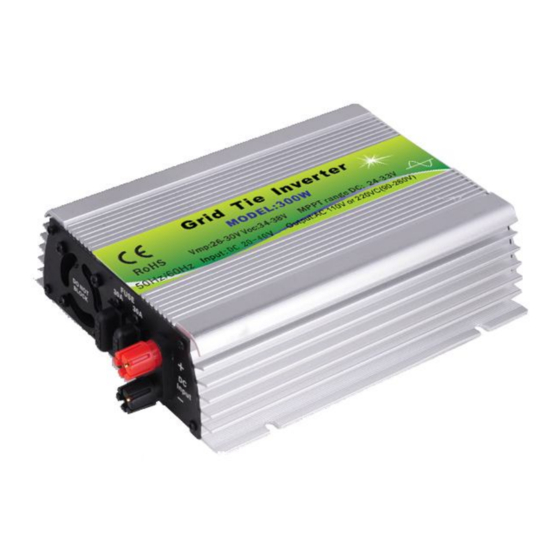
Smart Microinverter Introduction Smart grid tie inverter is a compact unit, which directly converts direct current into alternating current for powering appliances and/or office equipments and connecting to utility grid. The AC output from Smart Microinverter is synchronized and in-phase with the utility grid. It is a key device of power generation systems such as PV power generation system, wind turbine power generation system. -
Page 4: Important Safety Information
Advantages of Smart Microinverter 1. Unique circuit design, choice of import industrial electronic components, higher efficiency, more stable performance. 2. Creative MPPT technology, efficiency more than 99%, faster and more sensitive reaction, more reliable. 3. Parallel type design for DC input and modularization design for inverter, small volume, distributed installation, easy for system configuration, flexible for combination, strong expansibility of system. - Page 5 Safety Instruction Do not use Smart Microinverter in a manner not specified by the manufacturer. Doing so may cause death or injury to persons, or damage to equipment. Perform all electrical installations in accordance with all applicable local electrical codes.
-
Page 6: Technical Parameters
Technical Parameters Suitable for 60 cells solar panel which Vmp is 26-30V and Voc is 34-38V. Rated Power 500W Compatible with Solar 500-600W 60 cells Panels DC Input Range 20-40VDC MPPT Voltage 24-33VDC DC MAX. Current AC Output 120VAC/230VAC(90-260VAC) Frequency... -
Page 7: Installation
Packing Specification Packing Accessory Microinverter, AC Cord, User Manual(Warranty Card) Mechanical Size 21 x 16.5 x 5.3CM Net Weight/PCS 1.3KGS/PCS 31 x 21 x 11.5CM Inner Box (L x W x H) Carton(L x W x H) 42 x 31.5 x 35.5CM 6PCS/CTN, 8/11KGS Installation 1. - Page 8 4. AC power cable connects with Smart Microinverter and residential power grid which refers to low voltage civilian single-phase power grid. 5. Switch on power grid after check for input and output connections are correct and then switch on the Smart Microinverter. The red and green LED lights up at the same time and then red LED lights off follow on and green LED flash fast, it is means that Smart Microinverter is run for MPPT operation.When green LED long light and it is means that...
-
Page 9: Led Indicators
LED Indicators 1. Red LED indicator lights up under any conditions include but not limited: a) Low-voltage protection (DC input voltage lower than Min. input voltage of inverters), b) Over-voltage protection (DC input voltage higher than Max. input voltage of inverters), c) Over-temperature protection (inverters will shut down for power output when temperature of body of inverters higher than 65-70℃, and inverter will be automatically restart up when temperature... -
Page 10: General Troubleshooting
Troubleshooting a non-operating Smart Microinverter 1. System halted and /or without power output a) Check if switch of Smart Microinverter is turn on or not, b) Check if the DC connections to Smart Microinverter are correct or not, c) Check if any reverse DC connections for positive or negative or not, d) Check if DC input voltage is within the range of the Smart Microinverter’s or not, e) Check if the utility grid voltage and frequency are fit in with the... -
Page 11: Stack Wiring Diagram
Smart Microinverter Stack Wiring Diagram Smart Microinverter Three Phase output Wiring Diagram 9/13... -
Page 12: Warranty
Warranty Warranty Conditions Warranty Period: 15-year limited warranty period. Warranty Evidence: The B/L,Tracking no, and a completed warranty card. We grant an implied warranty of 1 year to the inverter from date of purchase for repair or replace the Defective Product free of charge includes freight cost. -
Page 13: Warranty Card
Warranty Card (Invalid Duplicate) Name Country and/or Territory Telephone Email Purchase Channels and/or Sources Models Date of Purchase Date of Installation Time of Using Brief Fault Description Improvement Suggestions Distributor and/or Sales Representative Distributor Name Telephone and/or Email Sales Representative Date of Customer Feedback... - Page 14 Other Supplementary Comments or Descriptions from Customers 12/13...
-
Page 15: Explore Applications Diagram
Explore Applications Diagram Work with 60 cells solar panel(Vmp:26-30V,Voc:34-38V) Work with wind turbine, output DC voltage is fit in with the range as specified and a 24V or 30V charge controller needed to be used if the wind turbine without build-in AC TO DC charge controller. Work with battery, PV module and wind turbine charging the battery and battery discharging to inverter for converting AC power which will feed into power grid.
