Advertisement
Quick Links
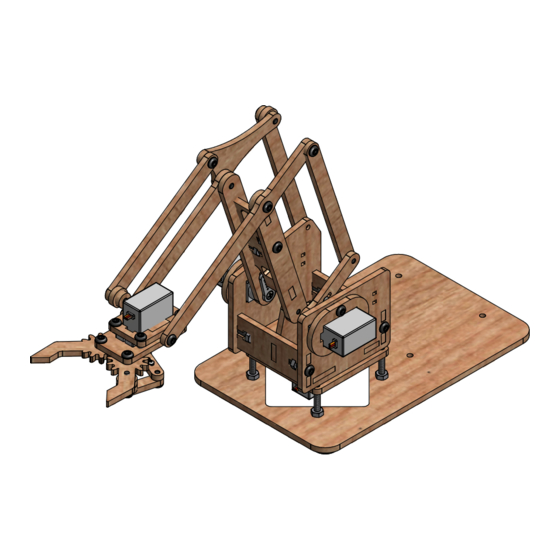
meArm v0.4 Assembly Manual
The meArm is a pocket sized, open source, robotic arm designed by Ben Gran of Nottingham, England.
This assembly manual was created by Scott Pierce (www.spiercetech.com)
Original assembly instructions can be found at: www.instructables.com/id/Pocket-Sized-Robot-Arm-meArm-V04/
Hardware source files can be found at: www.thingiverse.com/thing:360108
Software source code can be found at: www.github.com/phenoptix/MeArm
Alternate source code can be found at: www.instructables.com/id/MeArm-software
1
meArm Assembly Manual v0.4
www.spiercetech.com
Advertisement

Summary of Contents for Robot Arm meArm
- Page 1 Assembly Manual The meArm is a pocket sized, open source, robotic arm designed by Ben Gran of Nottingham, England. This assembly manual was created by Scott Pierce (www.spiercetech.com) Original assembly instructions can be found at: www.instructables.com/id/Pocket-Sized-Robot-Arm-meArm-V04/ Hardware source files can be found at: www.thingiverse.com/thing:360108 Software source code can be found at: www.github.com/phenoptix/MeArm...
- Page 2 Fasteners: Here are a list of fasteners required to build the meArm v0.4. The profiles below are actual size. Note: The Servo Screws and Servo Mount Screws reference in the assembly manual are included with the servos and do not need to be purchased seperately.
- Page 3 Pivot Servo Plate until the end of the screw is flush with the top of the Pivot Servo Plate Step 8: Tighten the M3 Nuts the rest of the way down onto the Base Plate meArm Assembly Manual v0.4 www.spiercetech.com...
- Page 4 Step 17: Insert (1) M3 x 6mm Screw into Parallel Linkage and position it as shown in the picture above. and thread it into the Servo Arm Extension Step 16: Insert Servo Screw that is supplied with the Servo meArm Assembly Manual v0.4 www.spiercetech.com...
- Page 5 Servo and position it as shown in the picture above. Step 26: Insert (1) M3 x 6mm Screw into the Parallel Linkage Step 25: Insert the Servo Arm Screw that is supplied with the Servo and thread it into the Right Arm Servo Plate meArm Assembly Manual v0.4 www.spiercetech.com...
- Page 6 Step 27: Insert (1) M3 x 6mm screw through the Left Arm Mount Tab and thread it into the Left Arm Base Joint Step 28: Attach Servo Arm to the Arm Bottom Plate using (2) Servo Mount Screws supplied with the Servo. meArm Assembly Manual v0.4 www.spiercetech.com...
- Page 7 Left Arm Base Joint to the Step 34: Join the Right Arm Servo Plate assembly to the rest Main Arm Cross Web of the assembly from the previous steps using (1) M3 Nut and (1) M3 x12mm Screw. meArm Assembly Manual v0.4 www.spiercetech.com...
- Page 8 Step 35: Attach the Arm Assembly to the Base assembly and then secure them together using the included Servo Screw. Step 36: Attach the Left Wrist Joint to the Parallel Linkage and the Left Arm Base Joint using (2) M3 x 6mm Screws meArm Assembly Manual v0.4 www.spiercetech.com...
- Page 9 Step 39: Attach the last hole of the Parallel Linkage Connector to the Parallel Linkage on the Right Arm Servo Plate using (1) M3 x 10mm Screw. Make sure to place (1) Spacer between the Parallel Linkage Connector and the Parallel Linkage. meArm Assembly Manual v0.4 www.spiercetech.com...
- Page 10 (1) M3 x 6mm Screw Step 47: Attach the Gripper Arm assembly from the previous step to the Servo assembly using (1) 9 Gram Servo Screw, (1) M3 x 12mm Screw, and (2) Spacers meArm Assembly Manual v0.4 www.spiercetech.com...
- Page 11 Spacer M3 x 10mm Screw Step 48: Attach the right side of the Gripper assembly to the rest of the meArm using (2) M3 x 10mm screws and (1) Spacer Step 49: Attach the left side of the Gripper assembly to the rest of the meArm using (1) M3 x 10mm screw meArm Assembly Manual v0.4...
Need help?
Do you have a question about the meArm and is the answer not in the manual?
Questions and answers