
Subscribe to Our Youtube Channel
Related Manuals for Peavey VSX 26e

Summary of Contents for Peavey VSX 26e
- Page 1 VSX™ 26e and VSX™ 48e Digital Loudspeaker Processors Operating Manual www.peavey.com...
- Page 2 (2) I’utilisateur de I’appareil doit accepter tout brouillage radioélectrique subi, même si le brouillage est susceptible d’en compromettre le fonctionnement. Warning: Changes or modifications to the equipment not approved by Peavey Electronics Corp. can void the user’s authority to use the equipment.
- Page 3 This manual covers both the VSX 26e and VSX 48e DSP processors. The units are essentially identical except for the number of inputs and outputs. Please read this guide carefully to ensure your personal safety as well as the safety of your equipment.
-
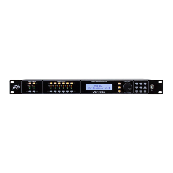
Page 4: Front Panel
Front Panel (1) USB port The USB "B" connector is used to connect a host computer for editing and control using the VSX Editor Program. (2) Process Function Buttons The process-function buttons are used to select a process for editing. Lighted buttons illuminate to indicate they are available selections. - Page 5 (5) LCD Display Used in conjunction with the front panel controls to edit processing parameters. (6) Output Mute Buttons Pressing the mute button alternately mutes and un-mutes the corresponding output. The button lights red when muted. (7) Output Edit Buttons Press this button to begin editing processes for the selected output.
-
Page 6: Operation
11) IEC POWER CORD CONNECTION and Fuse Holder This receptacle is for the IEC line cord (supplied) that provides AC power to the unit. It is very important that you ensure the unit has the proper AC line voltage supplied. Please read this guide carefully to ensure your personal safety as well as the safety of your equipment. - Page 7 Global Functions: Utility, Recall and Save Pressing the utility button opens the screens for system wide settings. Each press of the utility button advances to the next screen in the sequence. You can press the "Exit" button at any time to return to the main screen. Device ID #: (Utility Button) The ID number of the unit can be set in this screen.
- Page 8 Copy Settings: (Utility Button) Settings can easily be copied from one input channel to another input or from one output to another. Rotate the parameter encoder to select the parameter. Delay Units: (Utility Button) The units used to set delays can be selected on this screen. The options are milli-Seconds (mS), meters (m) or feet (ft) Load: (Recall Button) Rotate the Parameter knob to select the desired preset number then press to load.
-
Page 9: Input/Output Parameters
Input/Output Parameters The next section of controls are used to make adjustments to a particular input or output. Begin by pressing the "EDIT" button (7 and 9) for the channel you wish to adjust. The edit function buttons at the right side of the front panel that apply to the channel selection will light. The function selected will blink. Input Edit functions: Gain, PEQ, Link, Delay, X-Over and Polarity. - Page 10 Link Many times, in particular for stereo signals, you may want to make the same adjust to two or more channels at the same time. Using the link function, inputs can be linked to other inputs and outputs can be linked to other outputs.
- Page 11 Matrix The Matrix screen is only available when editing an output. This is where the inputs that drive each output are connected. The above screen shows input "A" as the signal source for output 1. If multiple inputs are selected, their signals are summed.
- Page 12 VSX™ Editor Program The VSX processors can be setup and controlled using the VSX Editor which runs on a Windows computer. To control the VSX, the computer can be connected to the VSX via USB, Ethernet, RS-232 or RS-485. For most applications, USB or Ethernet will be the preferred solutions.
- Page 13 Once connected, the setting from the unit will be loaded and the icon will turn green and indicate online. Use the Tabs at the top of the screen to navigate to the desired screen. Gain Screen The gain screen above gives a good overview of the system. In addition to showing input and output gains, mute and polarity status, Input and output equalization curves can be displayed.
-
Page 14: Compressor Screen
Compressor Screen The Compressor screen displays the settings of all 8 output compressors along with signal level, and limit status. The transfer function of a selected output is also displayed. - Page 15 Delay Screen All of the input and output delays are shown in the above screen. Delays can be adjusted using the sliders at the bottom, by sliding the speakers at the top or by direct typed entry. To directly enter the delay time, double click the delay time and type a new value.
- Page 16 Matrix Screen The input sources for each output are routed on the Matrix screen. Click the input button below the output to select. If more than one source is selected those inputs will sum. A graphical representation of the routing is given at the top.
- Page 17 Input Eqaulization Edit Screen The input equalization can be adjusted using this screen. When you select a PEQ band # at the bottom left of the screen, the parameters for that band can be adjusted using the PEQ Parameter sliders. A PEQ band can also be adjusted by selecting the corresponding band on the graph with the mouse and dragging it to set frequency and amplitude.
- Page 18 Output Equalization Edit Screen The output equalization can be adjusted using this screen. When you select a PEQ band # at the bottom left of the screen, the parameters for that band can be adjusted using the PEQ Parameter sliders. A PEQ band can also be adjusted by selecting the corresponding band on the graph with the mouse and dragging it to set frequency and amplitude.
-
Page 19: File Management
File Management Store (1) The store button at the bottom of the screen duplicates the store button on the front panel of the VSX. The user can select one of 30 user storage locations to save the current settings. Recall (2) The Recall button at the bottom of the screen duplicates the Recall button on the front panel of the VSX. -
Page 20: Specifications
Specifications Input Impedance: 20 k Ohms Output Impedance: 100 Ohms Frequency response Input to Output: +0/ -0.5 dB 10 Hz to 21 kHz +0/ -1.0 dB 10 Hz to 32 kHz Maximum Input level: +20 dBu Maximum Output level: +20 dBu THD + N @ 1 kHz: 0.007% Noise floor 22-22kHz... - Page 21 Sample Rate: 96 kHz Ethernet Interface: 10.0 Mbps Static IPv4 address RS 232 and RS 485: Baud Rate: 115200 Data bits: Parity: None Stop bits: RS 232/485 Pinout: RS 232 RX: Pin 2 RS 232 TX: Pin 3 RS 232 GND: Pin 5 RS 485 +: Pin 7...
Need help?
Do you have a question about the VSX 26e and is the answer not in the manual?
Questions and answers