Advertisement
GE Oil & Gas
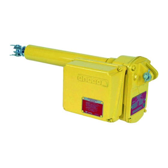
Andco Eagle Actuator
Installation Manual
NOTICE
The information contained in this manual is essential
to safe, successful, long term operation of your Andco
Eagle linear actuator. Read and follow the requirements
concerning storage, installation and adjustments. Failure
to do so could void the warranty covering your actuator.
This manual gives instructions for storing, installing,
operating and servicing the Model 3100 Eagle linear actuator.
Refer all questions not covered in this manual to:
GE Oil & Gas
16240 Port Northwest Drive
Houston, Texas 77041
Tel: 832-590-2306
Fax: 713-849-2879
Be sure to include the model and serial number
located on the nameplate of your Eagle actuator in all
communications and parts orders. The nameplate is
located on the gear housing cover.
Intent of Usage
The Andco Eagle Linear Actuator is a completely self-
contained electro-mechanical device. Its compact design
is equivalent in size to hydraulic or pneumatic cylinders.
Designed and fabricated for easy installation and
dependable long-life operation.
North American Sales Company - Serving Customers in California & Nevada - sales@nasco-corp.com - 310-459-8430
WARNING
PPE
Approved Personnel Protective
Equipment for the site must
be worn.
WARNING
GROUNDING LUG
Unit must be grounded with
minimum size 10 AWG wire.
These actuators feature:
• High-starting torque motor
with thermal overload protection
• Non-rotating extension rod
• Non-back driving acme screw
• All metal gearing
1.0 Storage Requirements
1.
Actuators should always be stored in a clean dry
environment, in a location where mechanical
damage to the actuator can't accidentally occur.
2.
All covers must remain in place and securely
fastened.
3.
All pipe plugs must remain in place and be kept tight.
4.
Actuators equipped with controllers can be
damaged by excessive moisture. Units so equipped
should be stored in a controlled environment
prior to installation. If the units are equipped
with compartment heaters, the heaters must be
continuously energized while in storage.
1.1 Lifting Instructions
1.
Do not lift Eagle actuator by limit switch
compartment.
2.
Follow applicable safety guidelines when lifting or
moving actuator.
2.0 Mounting Arrangements
NOTICE
While it is possible to mount the actuator in any position, it is not
recommended that the control compartment cover be positioned
face down. In order to maximize seal integrity, the unit should be
mounted with the extension rod pointed up (vertical installations) or
with motor on top (horizontal installations).
1.
The body tube adapter (57) is used for face flange or
trunnion-type mounting.
2.
The actuator can be clevis-mounted utilizing the clevis
(29) in the extension rod (6) and the rear clevis bracket,
located on the gear compartment cover (21).
Refer to Figure 1 on page 6.
Advertisement
Table of Contents

Summary of Contents for Andco Eagle
- Page 1 Be sure to include the model and serial number 1.1 Lifting Instructions located on the nameplate of your Eagle actuator in all Do not lift Eagle actuator by limit switch communications and parts orders. The nameplate is compartment.
-
Page 2: Installation Requirements
3.0 Installation Requirements b. Verify that the pins of the trunnion mounting WARNING configuration are parallel with the clevis pin. c. Tighten the nut and bolt arrangement of the body tube adapter to 50-55 ft-lbs. of torque. Approved Personnel Protective Equipment for the site must For Clevis mounting: Verify the pins of the Clevis be worn. - Page 3 5.0 Disassembly to cause excessive dehydration or gradual carbonization WARNING of any organic dust deposits on the actuator enclosure. MOVING PARTS The grounding lug on the actuator enclosure exterior Internal moving parts. Pinch must be wired to a suitable grounding system with a point hazard.
-
Page 4: Lubrication Instructions
Table 2 through the hole in the main housing (26) where the limit switch assembly (36) Every Eagle linear actuator has been lubricated for life at the factory and should not require further lubrication drive engages the helical gear (9). -
Page 5: Troubleshooting Guide
Check for excessive external load being actuated. d. Check for loss of lubricant. e. Check the extension rod for excessive contaminates. If you still have a specific problem with your Andco Eagle Actuator after making all of the above checks, contact GE for further assistance. - Page 6 Figure 1 - Eagle Outline Dimension Drawing...
- Page 7 Figure 2 - Eagle Actuator Parts Drawing...
-
Page 8: Parts List
Parts List 1. Flex nut 45. Motor pinion set screw 24. Pin 2. Wiper seal 46. Motor pipe plug 25. Motor gasket 3. Support washer 47. Position switch plunger 26. Actuator body housing 4. Drive screw 48. Slotted shaft 27. Motor 5. - Page 9 Figure 3 - Typical Wiring Diagram for Single Phase, Please refer to the wiring diagram came with your units before you work on the actuators.
- Page 10 Figure 4 - Typical Wiring Diagram for three Phase, Please refer to the wiring diagram came with your units before you work on the actuators.
- Page 11 Table 5 - Andco Eagle Technical Specifications -40 to 150°F Temperature -40 to 65°C Rating 90% Relative Humidity Canadian Applications US Applications Voltage Current (FL) Frequency Voltage Current (FL) (50 | 60HZ) Frequency 115 V 1Ph 2.6 A 60 HZ 110–120 1Ph...
- Page 12 *Denotes a trademark of the General Electric Company. All other marks are the property of their respective owners. GEA20318A Andco Eagle Actuator Installation Manual Rev. 06/2015 North American Sales Company - Serving Customers in California & Nevada - sales@nasco-corp.com - 310-459-8430...
Need help?
Do you have a question about the Eagle and is the answer not in the manual?
Questions and answers