
Related Manuals for Philips SQ 45


Summary of Contents for Philips SQ 45
- Page 1 User Manual SQ 45 SQ 4 5 High Performance Power Amplifier LBB 1342, 1343, 1344, 1346, 1347, 1348 Philips Communication & Security Systems...
- Page 2 ENGLISH Instructions for use page 1 TABLE OF CONTENTS Introduction page 1 Installation Controls Technical data...
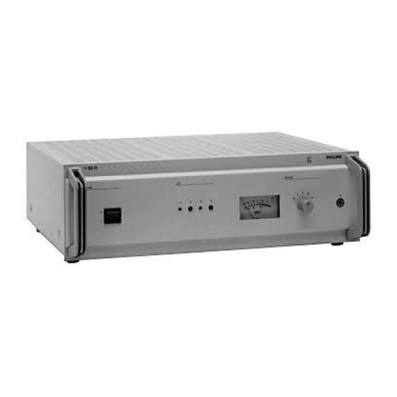
- Page 3 SQ 4 5 Fig. 1 - Front view Fig. 2 - Rear view Fig. 3 - Top view...
- Page 4 BLUE BLUE BLUE BLUE 240V 220V - 230V 127V 110V Fig. 4 - Mains connections 0V + 48 V DC Emergency battery supply Remote switch Open = DC power ON Closed = DC power OFF Fig. 5 - Battery supply CALL TEST INPUT 100V...
- Page 5 ENGLISH 1 INTRODUCTION The SQ 45 range of high performance audio The following list gives the amplifier power amplifiers have been designed for configurations (see fig.8) available in the smooth operation in professional Public Power Amplifiers series 100, 70 and 50 V Address projects.
- Page 6 monitoring of correct amplifier functioning. 2 INSTALLATION Extra equipment must be used to sample the signal; e.g The Amplifier Surveillance Board 2.1 Mains supply voltage (ASB) from the SM 40 range may be used. The unit as supplied is suitable for mains The outputs may be tapped at three different voltages of 220 - 230 V AC.
- Page 7 A replacement plug must be wired as follows: 2.4 Input connections earth - green/yellow neutral - blue Each of the amplifiers in the unit is provided live - brown with three inputs: ‘priority’, ‘music’ and ‘test’. The connections for these inputs, and the WARNING: wiring for the remotely controlled selection This apparatus must be earthed.
- Page 8 Mate-N-Lok sockets are mounted on the rear 2.7 Input sensitivity adjustment panel, (fig. 2). These are provided with The ‘priority’ input sensitivity is optimised corresponding plugs, and serve primarily as for use with the SM 40 or SM 30 system, transformer output connections to a variety and pre-set at 1 V on delivery.
- Page 9 systems, all similar loudspeaker terminals (in 3 CONTROLS (see fig. 1) most cases one terminal is marked with a red dot) must be connected to the same wire on 1 Mains on/off switch. the distribution cable. 2 Sensitivity control pre-set for ch-1, ch-2, ch-3 and ch-4 ‘music’...
- Page 10 T echnical Data SUPPLY Mains supply - voltage : 110 - 127 - 220/230 - 240 Volt at 50/60 Hz - inrush current limiter : 30 A Emergency battery supply - voltage : +48 V (polarity protected with ref. to ground) - inrush current limiter : 1 A Power consumption (max.
- Page 11 OUTPUT Output protection - The circuit is protected against any misloading, short circuit and oscillation on driving with any frequency. - The amplifier can withstand (without any damage) switching-on and switching-off of the power modules while delivering full output power and in case neither an input nor an output has been connected.
- Page 12 TERMINALS TERMINALS SM40 EXTENSION 600 mm 600 mm FRONT VIEW Fig.11 19” Rack mounting...
- Page 13 - Air gap for exit air flow (Min 400 cm 2 ). - Luftspalt fur Abluft (Min 400 cm 2 ). - Spleet voor afvoer luchtstroom (Min 400 cm 2 ). - Rendija de ventilacion para salida de corriente de aire (Min 400 cm 2 ). COOLING FANS - Canal d'evacuation du flux d'air (Min 400 cm 2 ).
- Page 14 Channel 2 Channel 3 Channel 1 Channel 4 100 V 100 V 100 V 100 V 70 V 70 V 70 V 70 V 50 V 50 V 50 V 50 V Fig.7 Loudspeaker connections...
- Page 15 LBB 1343/.. LBB 1342/.. LBB 1344/.. LBB 1348/.. Fig.8 Configuration types LBB 1346/.. LBB 1347/.. Fig.9 DIN-plug 180° Fig.10 Mate-N-Lok connector...
- Page 16 3922 988 33394 94-08 All specifications subject to modification without notice...
Need help?
Do you have a question about the SQ 45 and is the answer not in the manual?
Questions and answers