
Summary of Contents for STM SatLink VSAT
-
Page 1: User Guide
Networks without Barriers SatLink VSAT User Guide User Guide Revision 14.1.1-2 – January 12 2012... - Page 2 Moreover, STM shall not be held liable for errors that may occur herein or for incidental or consequential damage in connection with the furnishing, performance, or use of this material.
-
Page 3: Table Of Contents
INDOWS ONFIGURATION XP TCP/IP C ..................... 19 INDOWS ONFIGURATION USING THE SATLINK VSAT WEB INTERFACE ..................21 SATLINK VSAT CONFIGURATION AND LINE-UP USING THE WEB INTERFACE ...... 22 VSAT W ....................22 N TO THE NTERFACE VSAT P ............ 22... - Page 4 TESTING THE CONNECTION TO THE VSAT ..............131 APPENDIX E. MANAGEMENT VIA SNMP ....................140 APPENDIX F. ODU INSTALLATION ......................148 APPENDIX G. SATLINK 403X: INTERFACING VSAT RX/TX ANTENNAS .......... 154 Publication no. 101557 Page 3 (182) Copyright 2006-2012 – STM Group, Inc. Rev 14.1.1-2...
- Page 5 COMPLIANCE ........................177 APPENDIX M. STANDARDIZATION OF TIMING COMPENSATION ..........179 APPENDIX N. RECEIVER AND TRANSMITTER AUTOSTART ............. 180 APPENDIX O. ACCESSING THE FORWARD LINK SIGNALING ............181 Publication no. 101557 Page 4 (182) Copyright 2006-2012 – STM Group, Inc. Rev 14.1.1-2...
-
Page 6: Introduction
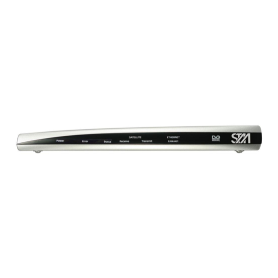
PCs to engage in two-way communication via a SatLink (or any DVB-RCS compliant) satellite network. Figure 1: SatLink 1000, 1910, 2000, and 2900 Indoor Units (IDUs) Figure 2: SatLink Outdoor Unit (ODU) Publication no. 101557 Page 5 (182) Copyright 2006-2012 – STM Group, Inc. Rev 14.1.1-2... -
Page 7: About This User Guide
SNMP The SatLink VSAT web interface is used as the main interface for initial configuration of the VSAT parameters and is presented in section 6. The status monitoring of the VSAT using a web interface is presented in section 7. Configuration via CLI is presented in section 9 and management via SNMP is presented in Appendix E. -
Page 8: Symbols
SatLink VSAT User Guide Symbols NOTE Additional information that the reader should pay special attention to. WARNING System malfunction may occur if the warning information is violated. Publication no. 101557 Page 7 (182) Copyright 2006-2012 – STM Group, Inc. Rev 14.1.1-2... -
Page 9: Unpacking
Stand for vertical placement (SatLink 1000 only) AC adapter (SatLink 1000/2000 only ) Power cord Brackets for 19‖ rack mounting (SatLink 1910 and SatLink 2900 only) Publication no. 101557 Page 8 (182) Copyright 2006-2012 – STM Group, Inc. Rev 14.1.1-2... -
Page 10: Installation
Do not work on the system or connect or disconnect cables during lightning storms. Follow these guidelines when working with electrical equipment: Disconnect all power and external cables before installing or removing a SatLink VSAT IDU. Do not work alone when potentially hazardous conditions exist. - Page 11 Coaxial 75 F-type jack for the cable to the BUC. TX coaxial jack Table 2: SatLink 2000 Rear Panel Description 3.2.2 SatLink 1000 Front and Rear Panel Figure 5: SatLink 1000 Front Panel Publication no. 101557 Page 10 (182) Copyright 2006-2012 – STM Group, Inc. Rev 14.1.1-2...
- Page 12 Coaxial 75 F-type jack for the cable to the BUC. TX coaxial jack Table 4: SatLink 1000 Rear Panel Description 3.2.3 SatLink 1910 Front and Rear Panel Figure 7: SatLink 1910 Front Panel Publication no. 101557 Page 11 (182) Copyright 2006-2012 – STM Group, Inc. Rev 14.1.1-2...
- Page 13 Coaxial 75 F-type jack for the cable to the BUC. TX coaxial jack Table 6: Description of SatLink 1910 Rear Panel 3.2.4 SatLink 2900 Front and Rear Panel Figure 9: SatLink 2900 Front Panel Publication no. 101557 Page 12 (182) Copyright 2006-2012 – STM Group, Inc. Rev 14.1.1-2...
-
Page 14: Idu Installation
Rubber feet on the bottom provide adequate clearance. Ensure that there is at least 10 cm clearance at the back to allow room for cable connections. Publication no. 101557 Page 13 (182) Copyright 2006-2012 – STM Group, Inc. Rev 14.1.1-2... -
Page 15: Odu Installation
Ensure that the airflow around the sides and back of the SatLink VSAT IDU is not restricted. The SatLink 1900/1901/1910/2900 can be mounted in any EIA-standard 19-inch telecommunications rack or cabinet. The STM SatLink 1000 and 2000 need to be placed on a shelf if either is to be placed in a rack. -
Page 16: Interface Connections
Do not connect and disconnect the coaxial cables with power connected to the VSAT IDU. Hint Use different color marking on the TX and RX coaxial cables to eliminate likelihood of interchanging the RX and TX coaxial cables. Publication no. 101557 Page 15 (182) Copyright 2006-2012 – STM Group, Inc. Rev 14.1.1-2... - Page 17 Ethernet hub, switch, or router, according to its manufacturer‘s instructions. The SatLink VSAT will auto-detect if Ethernet HUB or NODE mode is used and will automatically chose the correct mode; hence there is no need to use a cross-over Ethernet cable for direct connections to PCs.
-
Page 18: Connecting A Pc To The Satlink Vsat
Verify that the TCP/IP configuration is correct for PCs connected to the LAN that are to be used for your SatLink VSAT. Click on the Start button in Windows 7, select Control Panel, and then click Network and Sharing Center. Click Change Adapter Settings and right-click on the relevant Local Area Connection and select Properties. - Page 19 4.1.1 Dynamic IP Configuration of PCs Connected to the VSAT LAN By default, the DHCP server in the SatLink VSAT is enabled, and when the VSAT is powered on, all PCs connected to the VSAT LAN can automatically retrieve their IP configuration from the DHCP server. The user should verify that the Windows clients are configured to obtain an IP address and DNS server address automatically.
-
Page 20: Windows Xp Tcp/Ip Configuration
4.1.2 Static IP Configuration of PCs Connected to the VSAT LAN When the DHCP server in the SatLink VSAT is disabled, all PCs attached to the VSAT LAN must be configured with static IP addresses that are within the address range of the VSAT subnet. The IP configuration parameters to use for PCs connected to the VSAT LAN are supplied from the system operator or service provider. - Page 21 Note: The procedure for Dynamic and Static IP configuration of PCs connected to the VSAT LAN using Windows XP are the same as described in section 4.1.1 and section 4.1.2, respectively. Publication no. 101557 Page 20 (182) Copyright 2006-2012 – STM Group, Inc. Rev 14.1.1-2...
-
Page 22: Using The Satlink Vsat Web Interface
CLI via Telnet or the RS-232 port. To manage the SatLink VSAT via the web interface, start the web browser and type in the IP address of the VSAT in the address field as shown in Figure 18. The factory default IP address of the SatLink VSAT is 192.168.0.1. -
Page 23: Satlink Vsat Configuration And Line-Up Using The Web Interface
Configuring VSAT Parameters Required to Log on to the Hub The SatLink VSAT Web interface is used to configure a number of parameters before the VSAT can acquire the Forward Link and communicate with the Hub via the satellite connection. A default configuration specifying most of these parameters is pre-loaded on each VSAT, either in the factory or by the service provider before installation. - Page 24 LNBs that can be used with the VSAT are listed in Table 11 1) Click on the Configuration Satellite option in the SatLink VSAT home page. Figure 20: Configuring Receiver Parameters for Fixed VSAT Publication no. 101557 Page 23 (182) Copyright 2006-2012 –...
- Page 25 DVB-RCS system it belongs to based on the configured population ID. The population ID to be used is assigned by the Hub Operator. Enable Enable the table entry. Publication no. 101557 Page 24 (182) Copyright 2006-2012 – STM Group, Inc. Rev 14.1.1-2...
- Page 26 VSAT to operate together with transmitters other than the SatLink 403x. The valid ODU transmitters (BUC) used with the VSAT are listed in Table 9. 1) Click on the Configuration Satellite option in the SatLink VSAT home page. Figure 21: Configuring Transmitter Parameters Publication no. 101557 Page 25 (182) Copyright 2006-2012 –...
- Page 27 Find the position of the location where installing the VSAT using a standard GPS. The VSAT position is entered in the below format: degrees, minutes, seconds, and direction Publication no. 101557 Page 26 (182) Copyright 2006-2012 – STM Group, Inc. Rev 14.1.1-2...
- Page 28 SatLink VSAT User Guide 1) Click on the Configuration Satellite option in the SatLink VSAT home page. Figure 22: VSAT Positioning 2) Configure the VSAT positioning parameters as shown in the following table. Parameter Description Latitude Enter the latitude (deg, min, sec and direction).
- Page 29 DNS, NAT, and PEP configuration. Click on the Configuration IP option in the SatLink VSAT home page. Figure 23: IP Configuration – LAN, Management, and Virtual Interfaces 2) Enter the valid IP address and Netmask for the LAN, Management, and Virtual (Vir1-eth0) interfaces.
-
Page 30: Nat Configuration Using The Web Interface
Forward Link signal. If the bar is yellow, the signal can be received correctly with low link margin and if the bar is red, the signal Publication no. 101557 Page 29 (182) Copyright 2006-2012 – STM Group, Inc. Rev 14.1.1-2... - Page 31 3. Ensure that the VSAT transmitter is turned off and the TX cable from the VSAT to the ODU is connected. 4. Click the Lineup option in VSAT home page and configure the transmit EIRP level of the VSAT. Publication no. 101557 Page 30 (182) Copyright 2006-2012 – STM Group, Inc. Rev 14.1.1-2...
- Page 32 Beware of the risk of setting the IDU output level too high as a consequence of the antenna pointing not being sufficiently accurate. Publication no. 101557 Page 31 (182) Copyright 2006-2012 – STM Group, Inc. Rev 14.1.1-2...
- Page 33 4. Adjust the IDU output power in small steps (never more than 5 dB) based on feedback from the system operator. Publication no. 101557 Page 32 (182) Copyright 2006-2012 – STM Group, Inc. Rev 14.1.1-2...
-
Page 34: Test Of Connection To Hub
: 00:20:0e:10:35:34 Then do the following: 1) If the receiver is not already on, Click Configuration on the SatLink VSAT home page and start the receiver by clicking on the Start button to acquire the Forward Link. Publication no. 101557 Page 33 (182) Copyright 2006-2012 –... - Page 35 SatLink VSAT User Guide Figure 28: Receiver Configuration Publication no. 101557 Page 34 (182) Copyright 2006-2012 – STM Group, Inc. Rev 14.1.1-2...
- Page 36 5) If the proper connection is established to the Hub, the following status will be displayed on the Satellite Interface Status page: : ―Two-way link established‖ State Transmitter : ―On‖ : ―On‖ Receiver Publication no. 101557 Page 35 (182) Copyright 2006-2012 – STM Group, Inc. Rev 14.1.1-2...
-
Page 37: Prepare The Vsat For Normal Operation
1) Click on the Satellite option under Configuration in the SatLink VSAT home page and Configure the VSAT to automatically start the receiver by setting Auto Start to ―ON‖. The VSAT will automatically acquire the Forward Link. Setting the RX auto start to ―ON‖ will ensure that the receiver is started automatically after power failure, link failure, Hub restart, or a software failure, etc., without needing... - Page 38 SatLink VSAT User Guide Figure 31 : Receiver Auto Start Publication no. 101557 Page 37 (182) Copyright 2006-2012 – STM Group, Inc. Rev 14.1.1-2...
- Page 39 Hub restart, or a software failure, etc., without needing user intervention. Figure 32 : Transmitter Auto Restart 3) Click the Save button to save the configuration. Publication no. 101557 Page 38 (182) Copyright 2006-2012 – STM Group, Inc. Rev 14.1.1-2...
-
Page 40: Status Monitoring Using The Satlink Web Interface
7. Status Monitoring Using the SatLink Web Interface The SatLink web interface is used to display the status of the SatLink VSAT. An operator can view the status information of the satellite interface, packet and burst statistics, device information, the status of the DHCP server, and the status of mesh and terminal burst receiver. - Page 41 The satellite transmitter status option displays the detailed view of the receiver status. The operator can view the transmitter state, IDU output power, ODU output power, EIRP, Frequency offset, Timing offset, Capacity and SNR of the satellite transmitter. Publication no. 101557 Page 40 (182) Copyright 2006-2012 – STM Group, Inc. Rev 14.1.1-2...
-
Page 42: Statistics
LAN (Ethernet) and DVB (Satellite). For each interface, the table contains the number of IP packets and the number of bytes that have been received, transmitted, and discarded at the given interface. Publication no. 101557 Page 41 (182) Copyright 2006-2012 – STM Group, Inc. Rev 14.1.1-2... - Page 43 SatLink VSAT User Guide Figure 35: SatLink VSAT Statistics Multi-Field Classifier Statistics The Multi-Field Classifier table displays information about the configuration of the MFC table. A multi- field classifier is used by the VSAT to determine the QoS group an IP packet to be transmitted on the Return Link belongs to by performing a look-up in a classification table.
-
Page 44: Device Status
Specifies the serial number of the ODU for VSATs configured with a SatLink 403x ODU. Number Specifies the HW revision for VSATs configured with a SatLink 403x ODU. ODU HW Version Publication no. 101557 Page 43 (182) Copyright 2006-2012 – STM Group, Inc. Rev 14.1.1-2... -
Page 45: Dhcp Server Status
IP addresses to the LAN hosts for 15 minutes until it has acquired the network time. The DHCP server will apply the configured lease time when the network time is acquired. Publication no. 101557 Page 44 (182) Copyright 2006-2012 – STM Group, Inc. Rev 14.1.1-2... -
Page 46: Using The Command Line Interface Of The Satlink Vsat
Four levels of CLI user access rights are available for differentiating user privileges: Level 2: installer Level 3-5: end users When shipped from the factory, one user is pre-configured in the SatLink VSAT: User name Factory default password Privilege level install dvbrcs <ENTER>... -
Page 47: Logging Of Events
Logging of Events The SatLink VSAT logs certain events to a log stored in the RAM. See Appendix K.5 for a list of the log show different events and required actions. Use the CLI command to show the log in memory. -
Page 48: Cli Command Summary
<mode> dvb hdrcomp <mode> |-show dvb cr capacity <crClass> <CRA> <RBDCMax> <VBDCMax> dvb cr timeout <RBDCtimeout VBDCtimeout> dvb cr interval [-vbdc <interval>] dvb cr show [-timeout|-interval|-capacity] Publication no. 101557 Page 47 (182) Copyright 2006-2012 – STM Group, Inc. Rev 14.1.1-2... - Page 49 <destaddr> <netmask> <next hop> <ifnum> ip delroute <destaddr> [<netmask> [<next hop> CLI command is only available when corresponding SW license key is set Publication no. 101557 Page 48 (182) Copyright 2006-2012 – STM Group, Inc. Rev 14.1.1-2...
- Page 50 <info |stat {cid} | bklist > ]|[decomp <info | stat {cid} >] ip udpsend <options> ip udprecv <options> log file <enable|disable> [<severity> [<filesize>]] log show [<number> |<-all> |<-conf> | [-file <number>] Publication no. 101557 Page 49 (182) Copyright 2006-2012 – STM Group, Inc. Rev 14.1.1-2...
- Page 51 <value> [<pid>] [<addr>] [<port>] sw upgrade [-default] [<filename> [<tftp-ip-addr>]] sw restore sw show user add <username> <passwd> [<userlevel>] user del < username> user passwd [<oldpasswd> |<username>] <newpasswd> user show Publication no. 101557 Page 50 (182) Copyright 2006-2012 – STM Group, Inc. Rev 14.1.1-2...
-
Page 52: Power On And Log On
SatLink VSAT. Power On and Log On 1) To view the boot processes of the SatLink VSAT, connect a PC to the serial interface and launch a Terminal Emulator as described in Appendix A. Otherwise, go to step 2. - Page 53 3) Wait for the application software to be loaded and activated (typically takes 1-1.5 minutes). The power LED on the front of the SatLink VSAT will blink when the SW is booting and will stay on when the SW has successfully started. If watching the boot process on the RS-232 output, a printout similar to this will be displayed when the SW has booted: Loading application......
-
Page 54: Initial Configuration Of Parameters
If the input from the keyboard is not displayed when typing the username and password, check that the Local Echo is enabled in the Telnet client. 6) The SatLink VSAT should now be ready to be configured as described in the following sub-sections. Initial Configuration of Parameters The VSAT must be configured with a number of parameters before the VSAT can acquire the Forward Link and communicate with the network Hub. - Page 55 Example: # odu txtype 45 odu show This selects the JRC NJT5017F transmitter. Use the command to view the ODU configuration parameters. Publication no. 101557 Page 54 (182) Copyright 2006-2012 – STM Group, Inc. Rev 14.1.1-2...
- Page 56 Example: # odu antenna 13 odu show This selects the Patriot 1.2 m antenna. Use the command to view the ODU configuration parameters. Publication no. 101557 Page 55 (182) Copyright 2006-2012 – STM Group, Inc. Rev 14.1.1-2...
- Page 57 When ODU BUC is chosen to be the SatLink 403x transceiver, the LNB will automatically be set to the SatLink 403x. The SatLink VSAT will detect the SatLink transceiver model being used (i.e., SatLink 4033 or 4035) and display the detected model in the ODU...
- Page 58 To convert between the two formats use the formula 1/100 minutes = (seconds/60) x 100 Entering the direction as a number {0,1} selects format a, while entering the direction as a letter {„n‟,‟s‟,‟e‟,‟w‟} selects format b. Publication no. 101557 Page 57 (182) Copyright 2006-2012 – STM Group, Inc. Rev 14.1.1-2...
- Page 59 – Enter the CLI command dvb pos alt <height> where height = height in meters Example: # dvb pos alt 60 sets the altitude to 60 meters. Publication no. 101557 Page 58 (182) Copyright 2006-2012 – STM Group, Inc. Rev 14.1.1-2...
- Page 60 <idx> <pri> [<symbrate> [<freq> [<mode> [<popid> [<satpos> [<rxpol> [<txpol> [<satpolrot>]]]]]] Table index [0 – 9]. The SatLink VSAT can store up to 10 Forward Link entries and the table index is used to identify a single entry. For configurations with only one Forward Link entry, it is recommended to set this parameter to 0.
- Page 61 The above example shows the VSAT locked to a DVB-S2 Forward Link with: RX symbol rate: 24.500000 Msps RX frequency: 11.250000 GHz Mode: DVB-S2 Publication no. 101557 Page 60 (182) Copyright 2006-2012 – STM Group, Inc. Rev 14.1.1-2...
- Page 62 RX watchdog : 15 minute SymbRate[Msps] Freq[GHz] Mode PopId Enable 24.500000 11.250000 DVB-S2 2 1.200000 30.000000 DVB-S2 2 11.900000 11.000000 DVB-S2 2 Satellite (DVB) Receiver Status -------------------------------- Publication no. 101557 Page 61 (182) Copyright 2006-2012 – STM Group, Inc. Rev 14.1.1-2...
-
Page 63: Line-Up
Connect the RX cable between the ODU and IDU (if not already connected). Verify that the RX power level is between -25 dBm and -65 dBm at the input of the IDU. Publication no. 101557 Page 62 (182) Copyright 2006-2012 – STM Group, Inc. Rev 14.1.1-2... - Page 64 CLI output after successful acquisition of the Forward Link. The reader is referred to Appendix O for a description of the steps performed by the SatLink VSAT when acquiring the Forward Link. If the VSAT reports that RX tuning failed please check the following: ...
- Page 65 See Appendix I for a description of how to perform TX power calibration for other transmitters (BUCs). TX power level calibration and Return Link acquisition shall only be performed if the Forward Link has been acquired and is operating properly. Publication no. 101557 Page 64 (182) Copyright 2006-2012 – STM Group, Inc. Rev 14.1.1-2...
- Page 66 7. Contact the satellite operator / control center to clarify the line-up procedures for transmission power calibration and fine adjustment and verification of polarization of the VSAT. Publication no. 101557 Page 65 (182) Copyright 2006-2012 – STM Group, Inc. Rev 14.1.1-2...
- Page 67 Satellite (DVB) Transmitter Status -------------------------------- State : On (TDMA) IDU Output Power : -23.1 dBm ODU Output Power : 34.9 dBm EIRP : 46.1 dBW Es/No : 9.5 dB Publication no. 101557 Page 66 (182) Copyright 2006-2012 – STM Group, Inc. Rev 14.1.1-2...
-
Page 68: Test Of Connection To The Hub
: not set Model : SatLink 1000 HW ID : 103346 Main board ID : 120012 R1.2 MAC addresses: Ethernet (LAN) : 00:20:0e:10:17:15 Satellite (DVB) : 00:20:0e:10:17:15 Publication no. 101557 Page 67 (182) Copyright 2006-2012 – STM Group, Inc. Rev 14.1.1-2... - Page 69 Replace the IP address 10.10.10.4 with the actual IP address of the Hub router if the default IP configuration of the Hub is not used. Publication no. 101557 Page 68 (182) Copyright 2006-2012 – STM Group, Inc. Rev 14.1.1-2...
-
Page 70: Prepare The Vsat For Normal Operation
Verify that auto start is on for the transmitter by typing the CLI command save config 3. Save the configuration by typing the CLI command Publication no. 101557 Page 69 (182) Copyright 2006-2012 – STM Group, Inc. Rev 14.1.1-2... -
Page 71: Network Address Translation (Nat)
Please note that the CLI command applies both for static NAT and NAPT, even # ip nat show though the status output only mentions NAPT enabled. Publication no. 101557 Page 70 (182) Copyright 2006-2012 – STM Group, Inc. Rev 14.1.1-2... - Page 72 When using static NAPT, both the IP addresses and port numbers of the incoming packets will be substituted with the IP addresses and port numbers that are defined using the CLI command: # ip nat napt add <gladdr> <glport-first>[<port range>]<locaddr> [<locport>][<if>] Publication no. 101557 Page 71 (182) Copyright 2006-2012 – STM Group, Inc. Rev 14.1.1-2...
- Page 73 Entries in the Static NAT MAP Table are deleted using: ip nat static del <globaddr> <locaddr> ip nat show. To view entries in the NAT tables, use Publication no. 101557 Page 72 (182) Copyright 2006-2012 – STM Group, Inc. Rev 14.1.1-2...
- Page 74 Total Sessions 1964 Active Sessions Failed Sessions Packet Translations 169053 Release 14 allows transparent routing for LAN IP address when static NAT is used without dynamic NAPT. Publication no. 101557 Page 73 (182) Copyright 2006-2012 – STM Group, Inc. Rev 14.1.1-2...
-
Page 75: Quality Of Service
Critical Data and Real Time Video Conferencing are only available on the STM SatLink 1000, 1900, 1901, 2000, and 2900 when the software license key for 4 QoS classes has been set (see section 18.3). -
Page 76: Configuring Qos For The Return Link
QoS Group for this entry in the classification table. If a match is not found for an IP packet it will be treated as best effort traffic. Publication no. 101557 Page 75 (182) Copyright 2006-2012 – STM Group, Inc. Rev 14.1.1-2... - Page 77 DSCP value -all All filter masks. Used to delete an entry. ip qos show ip mfc show To view the current QoS configuration, use the CLI command Publication no. 101557 Page 76 (182) Copyright 2006-2012 – STM Group, Inc. Rev 14.1.1-2...
-
Page 78: Configuring The Vsat For Voip
1. All ViC traffic is mapped to QoS group 3. 2. ViC video is mapped to QoS group 3 and ViC audio + signaling is mapped to QoS group 4. Publication no. 101557 Page 77 (182) Copyright 2006-2012 – STM Group, Inc. Rev 14.1.1-2... -
Page 79: Dscp And Diffserv
26 (AF31; 011010) AF Class 3 low drop precedence 28 (AF32, 011100) AF Class 3 medium drop precedence 30 (AF33, 011110) AF Class 3 high drop precedence Publication no. 101557 Page 78 (182) Copyright 2006-2012 – STM Group, Inc. Rev 14.1.1-2... - Page 80 This is an applicable mapping for constant rate real-time applications like VoIP 46 (EF; 101110) This is an applicable mapping for variable rate real-time applications like ViC Publication no. 101557 Page 79 (182) Copyright 2006-2012 – STM Group, Inc. Rev 14.1.1-2...
-
Page 81: Bandwidth On Demand
Capacity for the ViC PHB group, and Rate Based Dynamic Capacity for the Critical Data PHB. In this example the VSAT requested 138 kbps of capacity and was granted by the Hub NCC a total of 156 kbps. Publication no. 101557 Page 80 (182) Copyright 2006-2012 – STM Group, Inc. Rev 14.1.1-2... - Page 82 Hub and is a network/service provider decision. The default value of this parameter is 0. This default value will be overwritten by the operator-defined value at logon time. Publication no. 101557 Page 81 (182) Copyright 2006-2012 – STM Group, Inc. Rev 14.1.1-2...
-
Page 83: Traffic Initiated Logon
13. Traffic Initiated Logon The SatLink VSAT can be configured to log on automatically to the DVB-RCS Hub when it has traffic to send and logoff again when it has had no traffic to send for a configurable timeout period. This mode is useful for VSAT installations where low power consumption is important (e.g., when powered by solar... -
Page 84: Header Compression
In this example, header compression is enabled on both the VSAT and the SatLink Hub. Always save config. remember to save the new configuration with the command Publication no. 101557 Page 83 (182) Copyright 2006-2012 – STM Group, Inc. Rev 14.1.1-2... -
Page 85: Disable Header Compression
: 45.0 dBW IDU Output Power : -15.2 dBm Es/No : 24.0 dB Header Compression : Disabled Timing correction : 153 us (10623 us) Frequency correction: -70 Hz Publication no. 101557 Page 84 (182) Copyright 2006-2012 – STM Group, Inc. Rev 14.1.1-2... -
Page 86: Routing Of Multicast Traffic
The above example will delete the static route of the multicast group with the IP address 224.0.2.2 from the Ethernet LAN to the satellite interface (Hub). save config Enter the CLI command to save the Return Link multicast configuration. Publication no. 101557 Page 85 (182) Copyright 2006-2012 – STM Group, Inc. Rev 14.1.1-2... -
Page 87: Updating The Vsat Sw
Do not use the CLI command to upgrade the software of the VSAT, since failure to delete old backup software version may block future automatic software upgrades. Publication no. 101557 Page 86 (182) Copyright 2006-2012 – STM Group, Inc. Rev 14.1.1-2... -
Page 88: Automatic Software Update
# sw mcast 1 511 224.0.1.59 2001 The above configuration will enable automatic reception of software upgrades on PID 511, IP address 224.0.1.59 and UDP port number 2001. Publication no. 101557 Page 87 (182) Copyright 2006-2012 – STM Group, Inc. Rev 14.1.1-2... -
Page 89: Manual Software Update
How to upgrade the VSAT software manually on the SatLink 2000 and SatLink 2900 The following example displays how to upgrade the VSAT software manually on the SatLink 2000/2900. Publication no. 101557 Page 88 (182) Copyright 2006-2012 – STM Group, Inc. Rev 14.1.1-2... -
Page 90: Restoring The Backup Software
Backup SW restored. Saving configuration and restarting Saving Configuration. This will take ~20 secs Configuration Saved Restarting Terminal. Connection will be closed Reconnect when the terminal has restarted (1-2 minutes) Publication no. 101557 Page 89 (182) Copyright 2006-2012 – STM Group, Inc. Rev 14.1.1-2... -
Page 91: Satlink And Dvb-S2
(indicated by the solid blue lines) that is only 0.7-1.0 dB from the theoretical Shannon limit (indicated by the dotted red lines); see Figure 39 below. This translates to an improvement Publication no. 101557 Page 90 (182) Copyright 2006-2012 – STM Group, Inc. Rev 14.1.1-2... - Page 92 SNR is 0.2 dB lower for normal frame than for short frame. However, the short FEC frame is useful in several circumstances, such as reducing delay when the Forward Link information rate is low. Publication no. 101557 Page 91 (182) Copyright 2006-2012 – STM Group, Inc. Rev 14.1.1-2...
-
Page 93: Dvb-S2 Coding And Modulation Control Modes
VSAT at a given time to select the suitable MODCOD for each. All signaling information is always transmitted at the lowest MODCOD with the best link margin in order to ensure that all VSATs are able to receive it. Publication no. 101557 Page 92 (182) Copyright 2006-2012 – STM Group, Inc. Rev 14.1.1-2... -
Page 94: Dvb-S2 Configuration For 1910 Idus With The Satlink 100 Plug-In Card
SatLink 100 plug-in card that is inserted into the expansion slot of the SatLink 1910. Units can be field-upgraded – there is no need to return units to STM for reconfiguration. The only requirement is that power is turned off when inserting the new extension card... - Page 95 DVB-S2 receive capabilities as default. Both models are configured the same way as the example shows above. If there is any doubt on whether a SatLink VSAT is capable of receiving DVB-S2, issue the CLI device show -dvbs2...
-
Page 96: Software Options
. Please contact the System Operator or ISP if access to a new software option is desired in order to receive a license key. Example: # sw license pep-tcp mykeyforenablingpeptcp Publication no. 101557 Page 95 (182) Copyright 2006-2012 – STM Group, Inc. Rev 14.1.1-2... -
Page 97: Generic Routing Encapsulation (Gre) And Ip Tunneling
GRE tunnel subnet into the GRE tunnel. Traffic arriving through the GRE tunnel is routed to the applicable interface. Publication no. 101557 Page 96 (182) Copyright 2006-2012 – STM Group, Inc. Rev 14.1.1-2... -
Page 98: Tcp Performance Enhancing Proxy (Pep)
TCP protocol over satellite links. The TCP PEP implementation in the SatLink System makes use of a TCP Performance Enhancing Server installed in the SatLink Hub and a PEP software client embedded in the VSAT. Publication no. 101557 Page 97 (182) Copyright 2006-2012 – STM Group, Inc. Rev 14.1.1-2... - Page 99 Indicates whether the VSAT is configured in Redirect or Transparent Mode PEP ServerAddress Shows that IP address of the Hub PEP Server that the VSAT PEP client is configured to interact with. Publication no. 101557 Page 98 (182) Copyright 2006-2012 – STM Group, Inc. Rev 14.1.1-2...
-
Page 100: Http Acceleration (Httpa)
If an object requested by the HTTP client is found in the SatLink VSAT‘s internal web-cache, the object will be delivered immediately. - Page 101 IPC bypass through address resolution via the VSAT DNS. Server addresses that are associated with unsupported mechanisms are automatically added to the dynamic server bypass list, allowing succeeding access to work properly. Publication no. 101557 Page 100 (182) Copyright 2006-2012 – STM Group, Inc. Rev 14.1.1-2...
- Page 102 # ip pep dynbypass –learnillegalreq - controlling bypass decision when server is accessed by an illegal request # ip pep dynbypass –learnall - switches on all learning methods Publication no. 101557 Page 101 (182) Copyright 2006-2012 – STM Group, Inc. Rev 14.1.1-2...
-
Page 103: Return Link Access Control (Rac)
Return Link traffic into different QoS classes. The command has a variable length where one or more tags with different tag parameters can be set. The Publication no. 101557 Page 102 (182) Copyright 2006-2012 – STM Group, Inc. Rev 14.1.1-2... - Page 104 MfC Classification table Module: QoS (0) SubIdx Idx Grp Classification Parms HitCount IPSrc= 10.10.10.10/255.255.255.255 Module: PEP (1) SubIdx Idx Grp Classification Parms HitCount Dst port = 1..65535 Publication no. 101557 Page 103 (182) Copyright 2006-2012 – STM Group, Inc. Rev 14.1.1-2...
-
Page 105: Vlan Extension (802.1Q)
Ethernet MAC bridge and thus the VLAN tag will not be carried through the SatLink network, but must be regenerated locally at the GRE egress point, if required. Let‘s say that operator wants to connect VLAN and VLAN over the same SatLink VSAT, connecting to two routers with addresses 10.20.1.1 and 10.20.1.2. -
Page 106: Ethernet User Priority (802.1P/D)
MFC. As required, the VSAT can be configured to map a specific user priority tag value to a specific QoS group. This effectively bypasses the IP header inspection, classification and Publication no. 101557 Page 105 (182) Copyright 2006-2012 – STM Group, Inc. Rev 14.1.1-2... -
Page 107: Dvb-S2 16-Apsk
QoS Group 18.7 DVB-S2 16-APSK To enable the SatLink VSAT (SatLink 1000 and 1910 Rev 3.x, SatLink 2000, and SatLink 2900) to receive 16-APSK DVB-S2 signals, the license key must be set to configure this. The below example sw show... - Page 108 SatLink VSAT User Guide PEP-TCP DVBS2-16APSK Publication no. 101557 Page 107 (182) Copyright 2006-2012 – STM Group, Inc. Rev 14.1.1-2...
-
Page 109: Extensions For Mobile Vsats
The transmit inhibit switch is connected to the SatLink 100 plug-in card at the two center pins of the RJ11 connector, as shown in Figure 41 below. When short-circuited, transmit inhibit function is activated. Publication no. 101557 Page 108 (182) Copyright 2006-2012 – STM Group, Inc. Rev 14.1.1-2... - Page 110 SatLink 100 for the SatLink 1910. The transmit inhibit switch is connected to the J1connector at pin 1 of the RJ45 connector for the input signal (Tx) as shown in Figure 42 below. Publication no. 101557 Page 109 (182) Copyright 2006-2012 – STM Group, Inc. Rev 14.1.1-2...
-
Page 111: Gps Interface
West, with a fix taken at 22:54:44 UTC. Data status is set to A, or active (can be set to V, or void). Checksum data is indicated by the 31 at the end of the string. The GPGGA GPS string concerns the global positioning system fix data. STM supports the following string: $GPGGA,123519,4807.038,N,01131.000,E,1,08,0.9,545.4,M,46.9,M,,*47... -
Page 112: Rx Lock Signal
TunerRetryTime to recover two-way communication faster after a blocking, but setting this parameter too high will cause longer outages in case of a real outage where Forward Link re-acquisition might be required to recover. Publication no. 101557 Page 111 (182) Copyright 2006-2012 – STM Group, Inc. Rev 14.1.1-2... -
Page 113: Mobile Vsat Lan Interface To Mobile Antenna Controller
VSAT wants to enter a SatLink network.) Note: The SatLink VSAT needs to have mobile license key. 19.5.2 Configure Antenna, BUC and LNB Types Currently the mobile VSAT software supports communication to SeaTel Antenna Controllers models DAC 2202 or DAC 2302. - Page 114 Configure the IP address of the Mobile Antenna Controller (which must be accessible through the IDU LAN interface), using the following CLI command: # odu antctrl ip <ipaddr> Publication no. 101557 Page 113 (182) Copyright 2006-2012 – STM Group, Inc. Rev 14.1.1-2...
- Page 115 : 5 sec Antenna Controller Status -------------------------------- Controller detected : yes SeaTel Comm Interface : Comm IF Ver 1.12 Port TCP-0 Signal Strength (AGC) : 112 Publication no. 101557 Page 114 (182) Copyright 2006-2012 – STM Group, Inc. Rev 14.1.1-2...
- Page 116 Use the CLI command ' ' to configure these parameters: # dvb rx fwdlink <idx> <pri> [<symbrate> [<freq> [<mode> [<popid> [<satpos> [<rxpol> [<txpol> [<satpolrot>]]]]]]] Publication no. 101557 Page 115 (182) Copyright 2006-2012 – STM Group, Inc. Rev 14.1.1-2...
- Page 117 ' to preserve the changes to the parameter configuration. 19.5.5 Configure the Forward Link Re-Acquisition Parameters The Forward Link re-acquisition parameters tune the behavior of the SatLink VSAT during the re- acquisition phase when several Forward Link entries are configured.
- Page 118 ‗attempts‘ number of times. If the SatLink VSAT still has not been able to re-acquire the Forward Link then it will try to search/acquire another Forward Link, the selection of the next Forward Link will be based on the priority parameter configured for the Forward Link entries.
-
Page 119: Mesh Vsats
The main advantage of mesh operation (compared to star) is the low latency for real-time traffic and reduced satellite bandwidth usage. STM‘s mesh-capable VSATs are the SatLink 2900 and SatLink1910. The CLI command device show in the example below shows the correct hardware required for the mesh operation (for the SatLink 1910):... - Page 120 Initialization (burst receiver in initialization state) Wait for CSC (the VSAT is trying to acquire its own transmitted logon burst) Coarse Sync (the burst receiver is synchronized with Publication no. 101557 Page 119 (182) Copyright 2006-2012 – STM Group, Inc. Rev 14.1.1-2...
- Page 121 10.10.50.0 / 255.255.255.0 Hub Address Space -------------------------------- IP Address Subnet Mask 10.10.11.0 / 255.255.255.0 The explanation of the displayed parameters is given in the following table: Publication no. 101557 Page 120 (182) Copyright 2006-2012 – STM Group, Inc. Rev 14.1.1-2...
- Page 122 LSE stands for Link Service Establishment. LSR stands for Link Service Release. The explanation of the displayed values is given in the table below. Publication no. 101557 Page 121 (182) Copyright 2006-2012 – STM Group, Inc. Rev 14.1.1-2...
- Page 123 Number of rejected link service establishments. LSR Ok Number of successful link service releases. LSR Error Number of link service releases that failed. Table 21: dvb mesh show -stat Configuration Parameters Publication no. 101557 Page 122 (182) Copyright 2006-2012 – STM Group, Inc. Rev 14.1.1-2...
-
Page 124: Definitions, Acronyms And Abbreviations
Multi Field Classifier Mcast Multicast Management Information Base Network Address Translation NAPT Network Address Port Translation Network Control Center OutDoor Unit Ortho-Mode Transducer Operating System Program Association Table Publication no. 101557 Page 123 (182) Copyright 2006-2012 – STM Group, Inc. Rev 14.1.1-2... - Page 125 Type Of Service Transport Stream Transmit User Datagram Protocol VBDC Volume-Based Dynamic Capacity VLAN Virtual LAN VoIP Voice Over Internet Protocol VSAT Very Small Aperture Terminal Publication no. 101557 Page 124 (182) Copyright 2006-2012 – STM Group, Inc. Rev 14.1.1-2...
-
Page 126: References
SatLink VSAT User Guide 22. References STM SatLink 4033/4035. 2W/3W Ku-band Transceivers. Installation Instruction, STM document No. 105894. SatLabs Group website at www.satlabs.org Digital Video Broadcasting website at www.dvb.org European Telecommunications Standards Institute website at www.etsi.org Digital Video Broadcasting (DVB); Interaction channel for satellite distribution systems, ETSI EN 301 790, V1.4.1... -
Page 127: Appendix A. Accessing The Command Line Interface Via Serial Console Port
SatLink VSAT directly to a COM port on a PC: Plug the 9-pin connector (DB09) (male) into the rear panel of the SatLink VSAT. Plug the 9-pin connector (DB09) (female) into a COM port on the PC. - Page 128 Select the COM port where the serial cable attached to the VSAT is connected and click OK. The COM port Properties box will appear, as shown in Figure 45. Figure 45: Hyper Terminal COM1 Properties Box Publication no. 101557 Page 127 (182) Copyright 2006-2012 – STM Group, Inc. Rev 14.1.1-2...
- Page 129 When closing the session and exiting HyperTerminal, allow the program to save the session, which will place an icon and session name into the HyperTerminal directory on the Start menu, allowing for future quick connections. Publication no. 101557 Page 128 (182) Copyright 2006-2012 – STM Group, Inc. Rev 14.1.1-2...
-
Page 130: Appendix B. Tftp Server
8 Kbytes in order to obtain satisfactory performance over the satellite link, in terms of acceptable download time. The VSAT can access a TFTP server on both the satellite and the Ethernet interface. Publication no. 101557 Page 129 (182) Copyright 2006-2012 – STM Group, Inc. Rev 14.1.1-2... -
Page 131: Appendix C. Telnet Client
When starting Tera Term, choose the Setup menu then Terminal. Enable Local echo as shown in Figure 46. Next, choose the Setup menu and then Save Setup to save this configuration. Tera Term may also be used as a replacement for HyperTerminal. Publication no. 101557 Page 130 (182) Copyright 2006-2012 – STM Group, Inc. Rev 14.1.1-2... -
Page 132: Appendix D. Testing The Connection To The Vsat
5 packets transmitted, 5 received, 0 percent packet loss rtt min/avg/max = 38/58/94 ms Description for usage 2: -stop stops a continuous ping started using ping <ipaddr> -t Example: Publication no. 101557 Page 131 (182) Copyright 2006-2012 – STM Group, Inc. Rev 14.1.1-2... - Page 133 The operator can use either the user. 3. Type FTP <LAN IP address of the terminal>. 4. Enter the correct user name and password. Publication no. 101557 Page 132 (182) Copyright 2006-2012 – STM Group, Inc. Rev 14.1.1-2...
- Page 134 7. Type [xxx could be any letter] to download from the VSATs LAN interface. 8. The same steps can be followed for downloading from the DVB interface. Publication no. 101557 Page 133 (182) Copyright 2006-2012 – STM Group, Inc. Rev 14.1.1-2...
- Page 135 You can use either root or install user. FTP <DVB IP address of the terminal> 3. Type 4. Enter the correct user name and password. Publication no. 101557 Page 134 (182) Copyright 2006-2012 – STM Group, Inc. Rev 14.1.1-2...
- Page 136 UDPSEND can either continuously pump traffic until explicitly stopped by the user or specified number of packets. The last used configurations will be stored until re-configured explicitly. Publication no. 101557 Page 135 (182) Copyright 2006-2012 – STM Group, Inc. Rev 14.1.1-2...
- Page 137 1. Before configuring the terminal, make sure to start the port listener and assign a port number. Port number of the listener should be same as that of the terminal. 2. Select Options View No packet loss on port listener. Publication no. 101557 Page 136 (182) Copyright 2006-2012 – STM Group, Inc. Rev 14.1.1-2...
- Page 138 UDPSEND will be automatically stopped after counting the number of packets pumped, or else you can stop the packet generator by using the stop command (i.e., you can stop the task using the taskstop command). Publication no. 101557 Page 137 (182) Copyright 2006-2012 – STM Group, Inc. Rev 14.1.1-2...
- Page 139 For UDP sender testing of the satellite link to hub, follow the below procedure. 1. Configure the port sender for IP address, port number, packet size, packets per second, and number of packets to be sent as shown here: Publication no. 101557 Page 138 (182) Copyright 2006-2012 – STM Group, Inc. Rev 14.1.1-2...
- Page 140 To check the statistics and the packet loss between the sender and the receiver, type the CLI ip udprecv show. command Publication no. 101557 Page 139 (182) Copyright 2006-2012 – STM Group, Inc. Rev 14.1.1-2...
-
Page 141: Appendix E. Management Via Snmp
IETF STD58 is supported. SNMP Version Compliance The SatLink VSAT supports SNMP version 2c as defined by IETF in RFC 1901 and RFC 3417. In accordance with SNMPv2c, the access rights associated with the attached community name is checked when an SNMP message arrives. The predefined access rights for the given community name, together with the predefined maximum access rights of the object ID(s) addressed by the SNMP message, determines the effective access rights. - Page 142 (1)...(19) ipAddrTable(20) ipNetToMediaTable(22) ipForward(24) rfc-2096 ipCidrRouteTable(4) icmp(5) udp(7) Figure 47: Supported Parts of MIB-II ipRouteTable and ipRoutingDiscards are not supported, ipForward.ipCidrRouteTable (RFC2096) is supported instead Publication no. 101557 Page 141 (182) Copyright 2006-2012 – STM Group, Inc. Rev 14.1.1-2...
- Page 143 E.3.3 MIB Object Definitions The STM DVB-RCS MIB is distributed separately in the standard ASN.1 syntax text file format used for an IETF STD58 compliant MIB. A set of MIB objects sufficient for the VSAT is available as a separate distribution.
- Page 144 SNMP request‘s IP address and net mask. # device snmp community public rw # device snmp show SNMP management access: ----------------------- Community String Access IpAddress Subnet public Read/Write 0.0.0.0 0.0.0.0 Publication no. 101557 Page 143 (182) Copyright 2006-2012 – STM Group, Inc. Rev 14.1.1-2...
- Page 145 To save a new value so that it will survive a VSAT power off/on, one must explicitly issue a MIB save command by setting the MIB object sysCmdSaveConfig to 1. Saving the configuration can take up to 20 seconds. Publication no. 101557 Page 144 (182) Copyright 2006-2012 – STM Group, Inc. Rev 14.1.1-2...
- Page 146 Then set the value to 5 (CreateAndWait) for the OID 1.3.6.1.4.1.3286.50.2.5.5.1.1.14.N, where N is the index desired for the new entry (index 3 in the example below). Figure 49: Define a New Row as CreateAndWait Publication no. 101557 Page 145 (182) Copyright 2006-2012 – STM Group, Inc. Rev 14.1.1-2...
- Page 147 Grp Cls CrM Pri QLength Drop Timeout Description 400000 120 Best Effort 15000 120 VoIP Audio 4000 120 VoIP Signaling QoS Classification table SubIdx Idx Grp Classification Parms HitCount Publication no. 101557 Page 146 (182) Copyright 2006-2012 – STM Group, Inc. Rev 14.1.1-2...
- Page 148 SatLink VSAT User Guide 3. Then activate the entry: Figure 51: Activating the Entry in the QoS Classification Table Publication no. 101557 Page 147 (182) Copyright 2006-2012 – STM Group, Inc. Rev 14.1.1-2...
-
Page 149: Appendix F. Odu Installation
Please refer to Appendix G for information of how to connect the SatLink 403x to antenna feed horn interfaces with 6 or 8 M4 screws. Publication no. 101557 Page 148 (182) Copyright 2006-2012 – STM Group, Inc. Rev 14.1.1-2... - Page 150 Place the transceiver on to the feed horn and insert one of the UNC screws for alignment. Tighten the screw loosely by hand or with an Allen key. Make sure that the rubber gasket is not removed from the groove when doing this. Publication no. 101557 Page 149 (182) Copyright 2006-2012 – STM Group, Inc. Rev 14.1.1-2...
- Page 151 Insert the remaining screws and tighten firmly with an Allen key. Always use screws from the mounting kit supplied with the SatLink 4033/4035 (part no. 105773). Do not use other screws or apply washers! Figure 56: Tightening with Allen Key Publication no. 101557 Page 150 (182) Copyright 2006-2012 – STM Group, Inc. Rev 14.1.1-2...
- Page 152 (or BUC/LNB/OMT), proceed with fine adjustment of antenna pointing and polarization assisted by the IDU as described in section 9.3. Publication no. 101557 Page 151 (182) Copyright 2006-2012 – STM Group, Inc. Rev 14.1.1-2...
- Page 153 Figure 58: Complete Assembled ODU with Cables Strapped to Antenna Feed Mount Important: Do not use amplifiers or attenuators on the TX-cable. Use type “F” connectors for the cables. Publication no. 101557 Page 152 (182) Copyright 2006-2012 – STM Group, Inc. Rev 14.1.1-2...
- Page 154 The cable pulling from the ODU to the IDU must be performed according to the customer. Sharp bends on the cables must be avoided (see figure below). Figure 59: Avoiding Sharp Bends on Cables Publication no. 101557 Page 153 (182) Copyright 2006-2012 – STM Group, Inc. Rev 14.1.1-2...
-
Page 155: Appendix G. Satlink 403X: Interfacing Vsat Rx/Tx Antennas
6 holes. SatLink 403x fits on this pattern by means of equally at 60 degrees apart. The SatLink 403x fits directly to this adapter SatLink 4901 (STM P/N 107268). pattern using 6 UNC screws for fastening. Publication no. 101557 Page 154 (182) Copyright 2006-2012 –... -
Page 156: Publication No
(option A or B) the antenna is configured with, and whether an adapter is required for mounting the SatLink 403x to the antenna feed horn. The STM SatLink 4901 adapter, having STM P/N 107268, can be ordered from STM. - Page 157 1. Remove the OMT. This part is not used when installing the SatLink 403x transceiver. 2. Use the adaptor SatLink 4901 (STM P/N 107268) to interface the SatLink 403x to a feed horn with interface C120 / 4 screws as shown in Figure 63 and Figure 64.
-
Page 158: Appendix H. Manual Configuration Of Parameters Normally Configured Automatically From The Hub
Configured Automatically from the Hub This Appendix explains how to configure manually using the CLI parameters that for most SatLink systems are configured automatically by the Hub NMS when the SatLink VSAT enters the network for the first time. Do not configure any of these parameters manually unless being instructed to do so by the Hub operator, as wrong configuration may break IP connectivity for the SatLink VSAT. - Page 159 If the prompt sign (#) does not show, press < DNS Configuration The DNS server the SatLink VSAT uses is normally configured automatically by the SatLink Hub. For a system where this is not done, the primary and, optionally, secondary DNS server IP addresses can be...
- Page 160 Note that when the internal SatLink DHCP server is enabled, the SatLink VSAT will configure the hosts on its LAN to use the SatLink VSAT as the primary DNS server, and its own DNS client‘s primary DNS server as the secondary DNS server. This is done in order to let the hosts use the DNS Forwarder of the SatLink VSAT to reduce the time for DNS lookups and especially improve the speed of Web browsing.
- Page 161 H.3.1 Changing the SatLink VSAT LAN Interface IP Address If the IP address of the SatLink VSAT LAN Interface is changed, the IP addresses of all end-user devices that are connected to the SatLink VSAT LAN must be updated correspondingly.
-
Page 162: Appendix I. Idu Power Calibration And P1Db Configuration With Bucs Other Than The Satlink 403X
Ensure that the TX and RX cables from the VSAT to the ODU are connected. restart Restart the SatLink VSAT (issue the CLI command ), wait until the application has loaded and the VSAT has locked to the received carrier. The receiver has successfully acquired the Forward Link... - Page 163 –27 Verify the setting by issuing the following CLI command: dvb tx show Save the setting by issuing the following CLI command: save config Publication no. 101557 Page 162 (182) Copyright 2006-2012 – STM Group, Inc. Rev 14.1.1-2...
- Page 164 -max -1 sets IDU Max Output Power to -1 dBm dvb tx outpow -max -3 sets IDU Max Output Power to -3 dBm Publication no. 101557 Page 163 (182) Copyright 2006-2012 – STM Group, Inc. Rev 14.1.1-2...
-
Page 165: Appendix J. The Boot Sw
In the boot-loader a minimal CLI is available, supporting the file system commands and access to the LAN. Type (question mark) to display the available CLI commands. Publication no. 101557 Page 164 (182) Copyright 2006-2012 – STM Group, Inc. Rev 14.1.1-2... -
Page 166: Appendix K. Troubleshooting
C:\ Telnet Microsoft Telnet> set localecho Local echo on Microsoft Telnet> To connect to the SatLink VSAT, type the command: Microsoft Telnet> open <ip-address> VSAT displays ―Receiver tuning failed for The VSAT is missing all or part of the …‖... - Page 167 The VSAT has been put in hold state by the Hub Operator. Only the Hub Operator can release it again. Contact the Hub Operator for assistance. Publication no. 101557 Page 166 (182) Copyright 2006-2012 – STM Group, Inc. Rev 14.1.1-2...
- Page 168 VSAT (use the CLI command 3. If the ping to the SatLink VSAT is successful, try to ping a known Internet address (e.g. www.google.com). If successful, the connection to the Internet is OK. If not OK check that the PC DNS IP address is correct. Try also to ping a known IP address on the Internet (e.g., ping 195.204.181.169).
- Page 169 ) procedure. Collecting Information if a Problem Occurs If a problem occurs with the SatLink VSAT for which support might be needed, having the information listed below available will be helpful. 1. The VSAT log from the HyperTerminal Window.
- Page 170 ID has been configured. After a timer has expired, the VSAT will retry logging on to the Hub. If the problem persists, please contact the Hub operator. Publication no. 101557 Page 169 (182) Copyright 2006-2012 – STM Group, Inc. Rev 14.1.1-2...
- Page 171 The VSAT was forced to restart due to following possible reasons, included in the log: Forward Link search has timed VSAT is unable to allocate memory Publication no. 101557 Page 170 (182) Copyright 2006-2012 – STM Group, Inc. Rev 14.1.1-2...
- Page 172 Please check that the ODU configuration matches the frequencies in use on the satellite and that the ODU in use is compatible with the IDU IF interface. Publication no. 101557 Page 171 (182) Copyright 2006-2012 – STM Group, Inc. Rev 14.1.1-2...
- Page 173 If again the ODU this happens more than once the ODU must be sent for must be sent for repair. repair. Publication no. 101557 Page 172 (182) Copyright 2006-2012 – STM Group, Inc. Rev 14.1.1-2...
- Page 174 Send the IDU for The IDU cannot access the satellite firmware repair. interface because failing to load the firmware. The IDU must be sent for repair. Publication no. 101557 Page 173 (182) Copyright 2006-2012 – STM Group, Inc. Rev 14.1.1-2...
- Page 175 LAN interface. VSAT. DNS server reply: Critical Change DNS server does not allow reply Recursion Not configuration of recursion. Available Hub DNS server to allow reply recursion. Publication no. 101557 Page 174 (182) Copyright 2006-2012 – STM Group, Inc. Rev 14.1.1-2...
- Page 176 Addr VSAT. BIP List Minor None. The VSAT has added a web site in the HTTPA bypass list. Events for Mesh capable only SatLink VSAT DLCP logon Normal None. The VSAT has successfully logged on to successful the Mesh Controller.
- Page 177 None. The VSAT has closed all dynamic links dynamic routes and and deleted all dynamic routes. This entries happens when the SatLink VSAT logs on / off from the Mesh Network. DLCP clear all session Normal None. The VSAT has closed all dynamic links data and logon and deleted all dynamic routes.
-
Page 178: Appendix L. Compliance
TR 101 790 v1.2.1. Digital Video Broadcasting (DVB); Interaction channel for Satellite Distribution Systems; Guidelines for the use of EN 301790 The SatLink 2000 has been tested compliant for the following VSAT profile: DVB-S2 CCM Profile Publication no. 101557 Page 177 (182) Copyright 2006-2012 – STM Group, Inc. Rev 14.1.1-2... - Page 179 EN 301 790 v1.4.1 2005-04-01 Digital Video Broadcasting (DVB); Interaction channel for satellite distribution systems TR 101 709 v1.2.1 2003-01-01 Digital Video Broadcasting (DVB); Interaction channel for satellite Publication no. 101557 Page 178 (182) Copyright 2006-2012 – STM Group, Inc. Rev 14.1.1-2...
-
Page 180: Appendix M. Standardization Of Timing Compensation
Never change the timing reference configuration without being instructed to do so by the system operator, as an incorrect timing reference configuration will prevent the VSAT from logging on to the Hub. Publication no. 101557 Page 179 (182) Copyright 2006-2012 – STM Group, Inc. Rev 14.1.1-2... -
Page 181: Appendix N. Receiver And Transmitter Autostart
Forward Link or NCR synchronization is lost, the VSAT will attempt to retune/reacquire the Forward Link regardless of rx autostart being enabled or not. Publication no. 101557 Page 180 (182) Copyright 2006-2012 – STM Group, Inc. Rev 14.1.1-2... -
Page 182: Appendix O. Accessing The Forward Link Signaling
The VSAT tunes to the transport stream of the Forward Link that it has pre-configured as the ―start-up‖ Forward Link. There it reads the NIT. The NIT PID value is hard-coded in the SatLink VSAT. In the NIT, the VSAT finds tuning parameters for accessing the satellite and Forward Link transport stream containing the RMT. - Page 183 If the Forward Link acquisition fails or comes to a stop, however, the Receiver State status (obtained by dvb rx show issuing the CLI command) will display the current stage in the acquisition process. Publication no. 101557 Page 182 (182) Copyright 2006-2012 – STM Group, Inc. Rev 14.1.1-2...
Need help?
Do you have a question about the SatLink VSAT and is the answer not in the manual?
Questions and answers