Table of Contents
Advertisement
Advertisement
Table of Contents

Subscribe to Our Youtube Channel
Summary of Contents for MPP Solar PCM60X
- Page 1 MPPT SOLAR CHARGER 3KW PCM60X User Manual Version 1.3...
-
Page 2: Table Of Contents
CONTENTS 1 ABOUT THIS MANUAL ................... 1 1.1 Purpose ...................... 1 1.2 Scope ......................1 1.3 SAFETY INSTRUCTIONS ................1 2 INTRODUCTION ....................2 2.1 Features...................... 2 2.2 Product Overview ..................3 3. INSTALLATION ..................... 4 3.1 Unpacking and Inspection ................4 3.2 Preparation .................... -
Page 3: About This Manual
1 ABOUT THIS MANUAL 1.1 Purpose This manual describes the assembly, installation, operation and troubleshooting of this unit. Please read this manual carefully before installations and operations. Keep this manual for future reference. 1.2 Scope This manual provides safety and installation guidelines as well as information on tools and wiring. -
Page 4: Introduction
2 INTRODUCTION Thank you for selecting this solar charge controller. This solar charge controller is an advanced solar charger with maximum power point tracking. Applying intelligent MPPT algorithm, it allows solar charge controller to extract maximum power from solar arrays by finding the maximum power point of the array. The MPPT battery charging process has been optimized for long battery life and improved system performance. -
Page 5: Product Overview
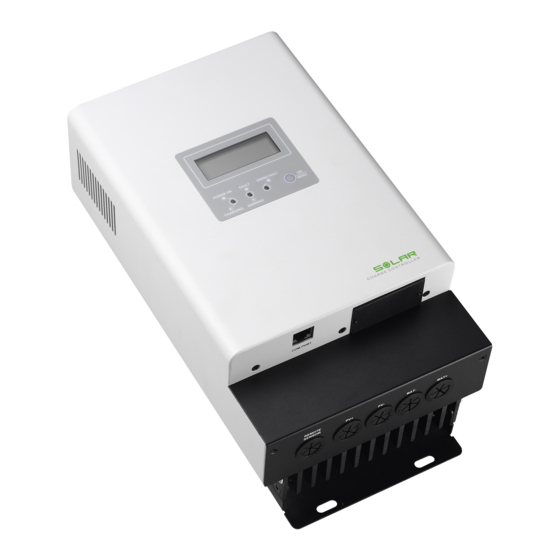
2.2 Product Overview 1. LCD display 2. Power On/Charging indicator 3. Fault and warning indicator 4. Wiring fault indicator 5. Operation button 6. PV connectors 7. Battery connectors 8. Remote temperature sensor terminal 9. Battery voltage sense terminal 10. Wiring box cover 11. -
Page 6: Installation
3. INSTALLATION 3.1 Unpacking and Inspection Before installation, please inspect the unit. Be sure that nothing inside the package is damaged. You should have received the following items inside of package: Solar charge controller x 1 User manual x 1 ... -
Page 7: Power Connection
Install the unit to the wall by screwing four screws. Refer to right chart. 3.4 Power Connection Wire size The four large power terminals are sized for 14 - 2 AWG (2.5 - 35 ) wire. The terminals are rated for copper and aluminum conductors. - Page 8 Connect the Power Wires WARNING: Shock Hazard The solar modules can produce open-circuit voltages in excess of 100 Vdc when in sunlight. Verify if solar input breaker or disconnect has been opened (disconnected) before connecting system wires. Connect terminals by following below steps (Refer to diagram above): 1.
-
Page 9: Grounding And Ground Fault Interruption
to the controller. 4. Connect positive terminal (+) of battery to the battery positive terminal (+) on the controller. 5. Connect negative terminal (-) of battery to one of the Common Negative terminals (-) on the controller. WARNING: Risk of Damage Be sure that solar connection is made with correct polarity. -
Page 10: Battery Voltage Sense
The RTS cable may be pulled through conduit along with the power wires. Tighten the connector screws with 5 in-lb (0.56 Nm) torque. NOTE: The RTS is optional package. Please check local dealer for the details. CAUTION: The controller will not activate temperature compensate charging function if the RTS is not used. -
Page 11: Communication Connections
A battery voltage sense connection is not essential required to operate your controller, but it is recommended for best performance. The battery voltage sense will ensure that the voltage display in LCD is very accurate. The voltage sense wires should be cut to length as required to connect the battery to the voltage sense terminal. - Page 12 Insert bundled software CD into a computer and follow on-screen instruction to install the monitoring software. For the detailed software operation, please check user manual of software inside of CD.
-
Page 13: Operation
4. OPERATION 4.1 Power-Up WARNING: Risk of Damage Connecting the solar module to the battery connector will permanently damage the controller. Confirm that the solar and battery polarities are correctly connected to the controller. A battery must be connected to the controller before operating it. The controller ... -
Page 14: Lcd Display Icons
Button Operation Function Action Description Power on Press the button until LCD backlight is on. Backlight on Press shortly Enter LCD setting mode Press the button for 3 seconds. Select LCD setting programs or modify Press shortly. parameter Confirm selection in setting programs Press the button for 1.5 seconds. -
Page 15: Lcd Setting
Indicate charging current. Indicates battery level by 0-24%, 25-49%, 50-74% and 75-100% in battery mode and charging status in line mode. Battery Charging Status. Status Battery voltage LCD Display <2V/cell 4 bars will flash in turns. Constant The right bar will be on and the 2 ~ 2.083V/cell other three bars will flash in turns. - Page 16 Program Description Options If “Use-Defined” is selected in program 02, this program 14.10V (Default) can be set up. The setting range is from 12.00V to 15.00V. If this program is Absorption voltage Increment of each short selected to modify, press is 0.01. Once the changeable value is achieved 15.00V, the...
- Page 17 Program Description Options The setting range is from 0mV to 60.0mV. Increment of each short press is 0.1 mV. The value will jump back to after 60.0mV 0mV (Default) temperature achieved. compensation ratio For each 12V battery, the derated battery charging voltage is followed the below formula:...
-
Page 18: Reference Code
Program Description Options Disable (Default) If equalization function is enabled in program 08, this program can be set up. If “Enable” is selected in this program, it’s activate battery equalization immediately and LCD main Equalization page will shows “ ”. activated Enable If “Disable”... -
Page 19: Charging Logic
CHARGING LOGIC 5.1 3-stage Charging In general, this solar charge controller is designed with 3-stage battery charging algorithm for fast, efficient, and safe battery charging. The following picture shows the sequence of charging stages. 1) Bulk charge stage In bulk charge stage, charge current begins to flow, typically at the maximum rate of the charge source. - Page 20 If the elapsed time of absorption stage is over setting value for C-V charging time, it will also transfer to Float stage. 3) Float Stage After the battery is fully charged in the Absorption stage, the controller will reduces the battery voltage to the setting point of Float voltage.
-
Page 21: Equalize Stage
Float cancel voltage Once the battery voltage drops to setting point of Float cancel voltage, the controller also returns to Bulk charging stage. Float cancel voltage = Floating charging voltage – (1V x battery numbers in series) 5.2 Equalize Stage Equalization function is added into solar charge controller. - Page 22 How to Apply Equalization Function You must enable battery equalization function in monitoring software first. Then, you may apply this function in device by either one of following methods: 1. Setting equalization interval. 2. Or, press the button for 3 seconds until LCD shows “ ”.
- Page 23 If solar charge controller is working in float stage, but at this time, the setting equalization interval (battery equalization cycle) is arrived, it will transfer to equalize stage. Equalize charging time and timeout In Equalize stage, based on maximum charging current of battery equalization, the controller will supply solar power to charge battery as much as possible until battery voltage raises to battery equalization voltage.
-
Page 24: Setting Parameter And Default Value
5.3 Setting Parameter and Default Value Recommended and default parameter settings are listed below. Battery Absorp. Float Equalize Equlize Absorp. Equalize Equalize Equalize Parameter type Stage Stage Stage Activation Time Time Timeout Interval Unit Volt Volt Volt En/Disable Minutes Minutes Minutes Days Default... -
Page 25: Parallel Charging Function
6. PARALLEL CHARGING FUNCTION This function is only applied to use “MPPTracker” software to control multiple chargers with Modbus or SNMP interface at the same time. Users can assign chargers in different groups. Refer to below chart for software setting screen. Chargers assigned in the same group will be parallel charged to the same batteries. -
Page 26: Trouble Shooting
7. TROUBLE SHOOTING Situation Fault Solution Fault Event Code Restart the charger. Over charge current If the problem remains, please contact your installer. Keep the charger in the cool environment. Over temperature If the problem remains, please contact your installer. Check the battery wire connection. -
Page 27: Specifications
8. SPECIFICATIONS Table 1 Electrical Specifications MODEL MPPT 3KW Nominal System Voltage 12, 24, or 48 VDC (Auto detection) Maximum Battery Current 60 Amps Maximum Solar Input 145V Voltage PV Array MPPT Voltage 60~115VDC Range 12 Volt--800 Watts Maximum Input Power 24 Volt--1600 Watts 48 Volt--3200 Watts PV Array voltage &... - Page 28 Solar high voltage disconnect Solar high voltage reconnect Battery high voltage disconnect Protections Battery high voltage reconnect High temperature disconnect High temperature reconnect Table 2 Battery Charging MODEL MPPT 3K Charging Algorithm 3-Step Charging stages Bulk, Absorption, Float Temperature compensation -5 mV / °C / cell (25 °C ref.) coefficient Temperature...
- Page 29 Charging Curve Table 3 Mechanical and Environment Charger MODEL MPPT 3K Product size (W x H x D, 315 x 165 x 128 Product weight (Kg) Ambient Temperature 0°C to 55°C Range Storage Temperature -40°C to 75°C Humidity 0%-90% RH(No condensing) Enclosure IP31 (indoor &...
Need help?
Do you have a question about the PCM60X and is the answer not in the manual?
Questions and answers