Sign In
Upload
Download
Table of Contents
Contents
Add to my manuals
Delete from my manuals
Share
URL of this page:
HTML Link:
Bookmark this page
Add
Manual will be automatically added to "My Manuals"
Print this page
×
Bookmark added
×
Added to my manuals
Manuals
Brands
AudioControl Manuals
Recording Equipment
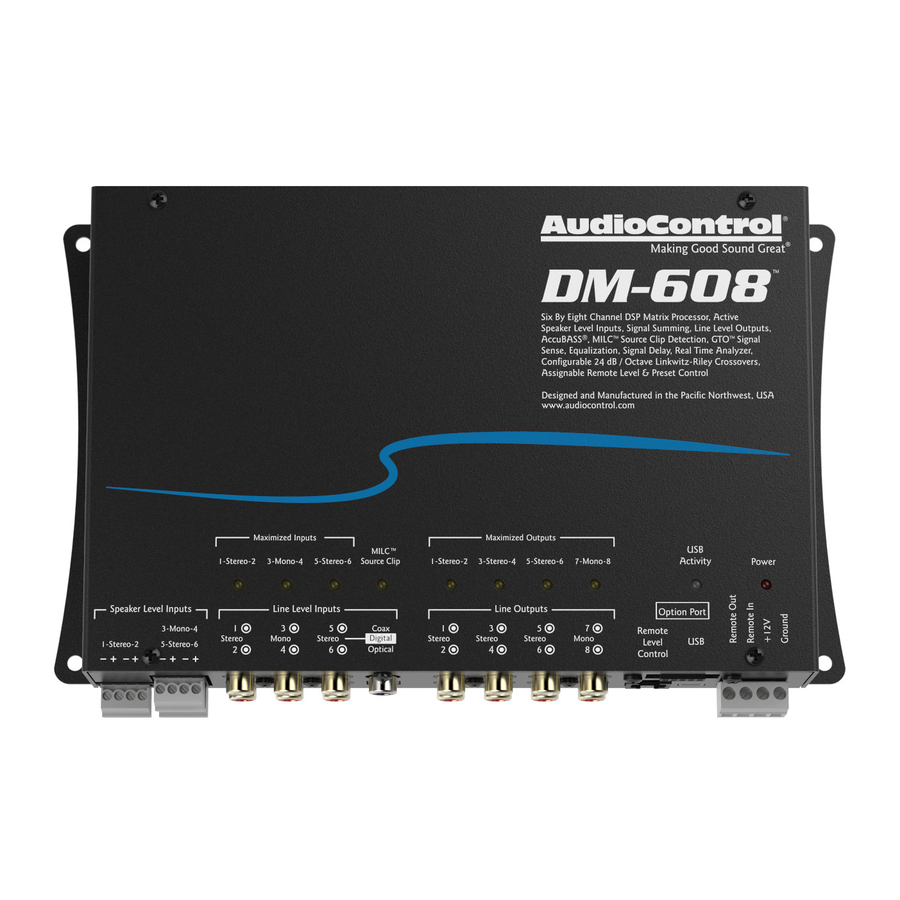
DM-608
Installation manual
AudioControl DM-608 Installation Manual
Dsp matrix processor
Hide thumbs
1
2
Table Of Contents
3
4
5
6
7
8
9
10
11
12
13
14
15
16
17
18
19
20
21
22
23
24
25
26
27
28
29
30
31
32
33
34
35
36
37
38
39
40
41
42
43
44
45
46
47
48
page
of
48
Go
/
48
Contents
Table of Contents
Troubleshooting
Bookmarks
Table of Contents
Important Safety Instructions
Table of Contents
Chapter 1: Introduction
Chapter 2: Quick Start Guide
Quick Start
Chapter 3: Hookup Diagrams
Subwoofer from
Chapter 4: Installation
Chapter 5: Features
Chapter 6: Installing the Application
Chapter 7: Updating the Firmware
Chapter 8: The Display
File Menu
Help Menu
Input Gain
Chapter 9: Troubleshooting
Chapter 10: Specifications
Installation Manual
Chapter 11: Service
Chapter 12: The Warranty
Salsa
Advertisement
Quick Links
1
Chapter 1: Introduction
2
Chapter 2: Quick Start Guide
3
Chapter 3: Hookup Diagrams
4
Chapter 4: Installation
5
Chapter 6: Installing the Application
6
Chapter 7: Updating the Firmware
7
Chapter 9: Troubleshooting
Download this manual
Six by Eight Channel
Eight by Ten Channel
DSP Matrix Processor
DSP Matrix Processor
Installation Manual
Table of
Contents
Previous
Page
Next
Page
1
2
3
4
5
Advertisement
Table of Contents
Need help?
Do you have a question about the DM-608 and is the answer not in the manual?
Ask a question
Questions and answers
Related Manuals for AudioControl DM-608
Recording Equipment AudioControl DM-810 Installation Manual
Dsp matrix processor (48 pages)
This manual is also suitable for:
Dm-810
Table of Contents
Print
Rename the bookmark
Delete bookmark?
Delete from my manuals?
Login
Sign In
OR
Sign in with Facebook
Sign in with Google
Upload manual
Upload from disk
Upload from URL


Need help?
Do you have a question about the DM-608 and is the answer not in the manual?
Questions and answers