
Related Manuals for KNEGT 254G2


Summary of Contents for KNEGT 254G2
- Page 1 Manual KNEGT 254G2 / 304G2 / 404G2 Knegt Quality Tractors Europe Habraken 2323L 5507TK Veldhoven Nederland TEL: +31 (0) 255 84 10 / FAX: +31 (0) 255 84 19 E-mail: info@knegt-international.com...
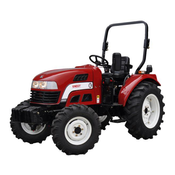
- Page 2 The KNEGT Brand wheeled tractor of Model 254G2/304G2/ 404G2 t is a newly developed product series of KNEGT BV. It is powered with the three-cylinder or four- cylinder diesel engines that have the features of ample output, less vibration and low noise as well.
-
Page 3: Table Of Contents
CONTENTS Safety Precautions…………………………………………………….. Work safely Always and safety Rules……………….……………….. Chapter I Safety Precautions…………………………………………………….. Safety Decals…………………………………………………………… Identifying You Machine……………………………………………….. Component Identification Plates……………………………………… Chapter II Operation……………...……………………………….………………... Seat Controls…………………………………………………………… Seat Belt………………………………………………………………… Clutch Pedal…………………………………………………………….. Forward/Reverse Lever………………………………………………… Range Shift Lever………………………………………………………. PTO Gear Selection Lever…………………………………………….. Front Wheel Drive (4WD) Lever………………………………………. Hand Operated Throttle Lever…………………………………………... - Page 4 Chapter III Routine Maintenance…………………………………………………… Service Schedules……………………………………………………… Fluids, Lubricants and Capacities…………………………………….. Safety Checks…………………………………………………………… Greasing…………………………………………………………………. Chapter IV Technical Specifications of the Tractor……………..………………… Parameters of the tractor………………………………………………. Main technical specifications of the engine………………………….. Drive system…………………………………………………………….. Traveling and Steering System………………………………………... Working devices………………………………………………………… Electric apparatus and instrument…………………………………….. Filling capacity…………………………………………………………...
-
Page 5: Safety Precautions
Safety Precautions ★Recognize Safety Information This is a safety—alert symbol.When you see this symbol on your machine or in this manual,be alert to the Potential for personal injury. Follow recommended precautions and safe operating practices. ★Understand Signal Words A signal word—DANGER,WARNING,or CAUTION—is used with the safety.alert symbol.... - Page 6 ★Use Seat Belt and Foldable ROPS Properly—Open Station When the ROPS is in the“up”or extended position, ALWAYS use your seat belt to minimize chance of injury from an overturn accident DO NOT use seat belt when ROPS is folded down. This tractor is equipped with a foldable Roll-Over Protective Structure (ROPS).The ROPS (A) should be kept in the “up"...
- Page 7 ★Operate Tractor Safely Features designed into your tractor make operation Safer and let it perform a wide variety of jobs.Use your tractor only for specified jobs it was designed to perform:implement carrier,load mover,remote power source,or transport Unit—not a recreational vehicle. Careless use or misuse can result in unnecessary accidents.Be alert to hazards of tractor operation....
- Page 8 With mechanical front wheel drive engaged,the Tractor can climb steeper slopes but it does not become More stable.When this option is used,extra caution is needed on slopes.Compared to a 2-wheeI drive, a front. Wheel drive tractor maintains traction on steeper slopes,increasing the possibility of a tip over....
- Page 9 ★Freeing a Mired Machine Attempting to free a mired machine can involve safety hazards such as the mired tractor tipping rearward,the towing tractor overturning,and the tow chain or tow bar (Actable is not recommended) failing and recoiling from its stretched condition. Back your tractor out if it gets mired down in mud....
- Page 10 ★Park Tractor Safely To park tractor safely: ·Disengage PTO. ·Lower equipment to the ground. ·Put gear shift lever in NEUTRAL. ·Apply hand brake. ·STOP the engine. ·Remove key. Before you leave the operator's seat,wait for engine and attachment parts to stop moving. ★Handle Fuel Safely-Avoid Fires Handle fuel with care;it is highly flammable.Do not Refuel the machine while smoking or when near open...
- Page 11 ★Wear Protective Clothing Wear close fitting clothing and safety equipment appropriate to the job. Prolonged exposure to loud noise can cause Impairment or loss of hearing. Wear a suitable hearing protective device such as earmuffs or earplugs to protect against objectionable or uncomfortable Loud noises....
- Page 12 ★Use Safety Lights and Devices Prevent collisions between other road users,slow moving tractors with attachments or towed equipment,and self-propelled machines on public roads.Frequently check for traffic from the rear,especially in turns, and use turn signal lights. Use headlights,flashing warning lights,and turn Signals day and night.Follow local regulations for Equipment lighting and marking.Keep lighting and marking visible,clean,and in good working order....
- Page 13 Tow Loads Safely ★ Stopping distance increases with speed and weight of towed loads,and on slopes.Towed loads with or without brakes that are too heavy for the tractor or are towed too fast can cause loss of control.Consider the total weight of the equipment and its load. Observe these recommended maximum road speeds,or local speed limits which may be lower:...
- Page 14 Securely support any machine elements that must be raised for service work. Keep all parts in good condition and properly installed.Fix damage immediately.Replace worn or broken parts. Remove any buildup of grease,oil,or debris. On self-propelled equipment,disconnect battery ground Cable (一) before making adjustments on electrical systems or welding on machine....
- Page 15 ★Support Machine Properly Always lower the attachment or implement to the ground before you work on the machine.If you must work on a lifted machine or attachment,securely support the machine or attachment.If left in a raised position, hydraulically supported devices can settle or leak down. Do not support the machine on cinder blocks,hollow tiles,...
- Page 16 ★Store Attachments Safely Stored attachments such as dual wheels, cage wheels and loaders can fall and cause serious injury or death. Securely store attachments and implements to prevent falling. Keep playing children and bystanders away from storage area. ★Prevent Acid Burns Sulfuric acid in battery electrolyte is poisonous.It is strong enough to burn skin,eat holes in clothing,and cause blindness if splashed into eyes....
- Page 17 ★Dispose of Waste Properly Improperly disposing of waste can threaten the environment and ecology.Potentially harmful waste used with equipment include such items as oil,fuel, coolant,brake fluid,filters,and batteries. Use leak proof containers when draining fluids.Do not use food or beverage containers that may mislead someone into drinking from them....
-
Page 18: Chapter I
Chapter Ⅰ Work Safely Always and Safety Rules Safety First This warning sign alerts you about important messages involving your safety. Read these safety rules attentively and strictly follow suggested 0precautions to avoid any potential danger and safeguard your health and personal safety. Important Notices This tractor has been designed and manufactured specifically and solely for agricultural use. -
Page 19: Safety Precautions
If you are unsure about anything, ask your East Wind dealer or employer. Do not guess, you or others could be killed or seriously injured. Maintenance Use genuine KNEGT parts only. Failure to do this will: —Cost you more —Not result in complete satisfaction. - Page 20 It is extremely dangerous to operate machinery when under the influence of alcohol or drugs. Do not consume alcoholic drinks or take drugs before or while operating the machine or attachments. Be aware of medicines which can cause drowsiness You can be injured if you do not wear the proper clothing.
- Page 21 Airborne particles of light combustible material such as straw, grass, wood shavings, etc. must not be allowed to accumulate within the engine compartment or in the propshaft guards (when fitted). Inspect these areas frequently and clean at the beginning of each work shift or more often if required.
- Page 22 Oil is toxic. If you swallow any oil, do not induce vomiting, seek medical advice. Used engine oil contains harmful contaminants which can cause skin cancer. Do not handle used engine oil more than necessary. Always use barrier cream or wear gloves to prevent skin contact. Wash skin contaminated with oil thoroughly in warm soapy water.
-
Page 23: Safety Decals
Safety Decals WARNING Decals on the machine warn you of particular hazards. You can be injured if you do not obey the decal safety instructions. Each decal is attached close to a part of the machine where there is a possible hazard. - Page 24 Keep ROPS Installed Properly Freeing a Mired Machine. Do not maintenance and filling when the tractor is working. Do not trample. Operators handbook. Filling the tank. Checking and adjusting the fluid level. Use the seat belt.
- Page 25 Shifting handle of high-low speed range. A2 B2 A1 B1 output input output input Define of Remote hydraulic control valve. neutral A2 B2 A1 B1 input output input output Define of Remote hydraulic valve. Engine speed control, Key Switch. Engine speed control, hand operated throttle lever.
-
Page 26: Identifying You Machine
Identifying your machine Machine Identification Plate Your machine has an identification plate mounted on the front right hand side of the machine. Information contained on this plate includes Model, Type, Engine, Vehicle Identification Number, Manufacturer and Address. The machine and engine serial numbers can help identify exactly the type of equipment you have. -
Page 27: Component Identification Plates
Component Identification Plates Engine Identification Plate Location The engine identification plate C is attached to the left hand side of the engine block. The information contained on this plate includes the engine model and serial number. ROPS Certification Plate Your machine is built to the ROPS standard and has an identification identification label is shown below . -
Page 28: Operation
Use your handbook to identify each control lever, switch, gauge, button and pedal. Do not guess. If there is anything you do not understand, ask your KNEGT distributor. When you have familiarized yourself with the operating controls, gauges and switches, practice using them. -
Page 29: Seat Controls
c .Clean all safety decals. Replace any that are missing or cannot be read. . Check for damage. a. Inspect the machine generally for damaged and missing parts. b. Make sure that all pivot pins are secured correctly in place. c. -
Page 30: Seat Belt
Seat Belt Fasten the Seat Belt 1. Sit correctly in the seat. 2. Push the male fitting A into the buckle B until it latches into position. Make sure the seat belt is not twisted and that it is over your hips not your stomach. WARNING If you do not wear your seat belt you could be thrown out of the machine and crushed. -
Page 31: Range Shift Lever
Forward/Reverse Lever Stop the machine before moving this lever. To select forward F, or reverse R, move the lever to the required position. When used in combination with the main gear lever and the range shift lever eight forward and eight reverse speeds can be achieved. -
Page 32: Front Wheel Drive (4Wd) Lever
The PTO gear selection lever A enables two gears to be selected to drive the two speed PTO, giving speeds suitable for a range of applications and conditions. This lever is located to the left of the operator’s seat. With first gear selected, a PTO shaft speed of 540 rpm is achieved, and with second gear selected, 1000 rpm. -
Page 33: Left And Right Turn Brake Pedals
Left and Right Turn Brake Pedals The left and right turn brake pedals A assist when making tight turns in a field. Use these pedals in conjunction with the steering wheel. For normal braking, connect the left and right turn brake pedals together with the latch B. Always use the latch B when travelling on the road or at high speed. -
Page 34: Lowering Speed Control
pull the lever backwards. To lower the implement, push the lever forwards. To achieve a consistent working depth, adjustable stops B can be set to ensure the implement returns to the same depth each time. Lowering Speed Control The lowering speed control A is situated in the centre of the seat bulkhead. -
Page 35: Switches And Instruments
Switches and Instruments A Tachometer This gauge shows the revolutions of the engine and the hours the machine has been used. The hour meter consists of five digits, with the last digit indicating 1/10th of an hour. B Temperature Gauge and Fuel Gauge On the coolant temperature gauge, B indicates temperature .When engine works normally, the water temperature should be within 80 —... -
Page 36: Key Switch
Key Switch The Key switch is operated by the starter key. It has four positions. The key can only be inserted or removed when in the OFF position A Turn the key to this position to stop the engine. B Turning the key to this position connects the battery to the electrical circuits The key will. -
Page 37: Before Starting The Engine
Remove oil, grease and mud from the pedals, control levers and the steering wheel. d. Make sure that your hands and shoes are clean and dry. e. Inspect the ROPS structure for damage. Get your KNEGT Distributor repair any damage. Make sure all its securing bolts are fitted and correctly tightened. -
Page 38: Starting The Engine
Starting the Engine Exhaust Gases WARNING Breathing the machine exhaust gases can harm and possibly kill you. Do not operate the machine in closed spaces without making sure there is good ventilation. If possible, fit an exhaust extension. If you begin to feel drowsy, stop the machine at once and get into fresh air. -
Page 39: Operating Environment
In very low temperatures, say-18°C and below, additional starting aids may be needed. Examples are fuel, oil and coolant heaters and extra batteries. Ask your KNEGT Dealer for advice. Note: Do not connect two batteries in series to give 24 volts for starting. This could burn out starter motor. -
Page 40: Working With Your Machine
Working With Your Machine Operating Practices and Site Safety This section explains some techniques for efficient and safe use of the machine and its attachments/implements. Read and understand this section before you start working with the machine. Practice using the attachments/ implements until you are completely familiar with the controls and what they do. - Page 41 When moving the machine, keep it under control at all times. Stay alert for obstructions and possible hazards. Moving Off Check your seat 1. Make sure that the seat is secure and correctly adjusted. Make sure your seat belt is fastened and the steering wheel is correctly adjusted.
- Page 42 Engaging the Differential Lock When wheel slippage is encountered, press down on the differential lock pedal to engage the differential lock. Disengaging the Differential Lock To disengage the differential lock, remove your foot from the differential lock pedal. Note: If the differential lock does not disengage when you remove your foot from the differential lock pedal, use both the left and right turn brake pedals until the differential lock disengages.
- Page 43 Working on Slopes WARNING Failure to observe these precautions may cause the machine to become unstable and in extreme circumstances will overturn with potential serious injury to the operator. Uneven Terrain Pre-plan your movement over uneven terrain. Avoid wheel slippage and spinning. Pass diagonally through sharp dips.
-
Page 44: Attaching Implements
Adjusting the Lower Link Adjustment of the lower link A is achieved with the adjusting handle B on the yoke rod. To shorten or lengthen the yoke rod, turn the adjusting handle in the required direction. When the correct adjustment is achieved, secure the turn buckle with the stopper provided. - Page 45 Raising and Lowering Implements Implements can be raised and lowered with the hydraulic position control lever. To ensure consistent working depth: 1. Move the hydraulic position control lever until the implement is at the required depth. 2. Release the adjustable stop and move it until it touches the hydraulic position control lever.
-
Page 46: Transporting The Machine
Disconnection 1. Lower the implement to the ground. 2. Relieve the hydraulic pressure in the hoses by operating the relevant auxiliary valve lever with the engine stopped. 3. Clean around the connections. 4. Disconnect the implement at the connections on the remote hydraulic control valve. - Page 47 WARNING Before moving the machine onto the trailer, make sure that the trailer and ramp are free from oil, grease and ice. Remove oil, grease and ice from the machine tyres. Make sure the machine will not foul on the ramp angle.
-
Page 48: Routine Maintenance
It can be seen from the Service Schedules on the following pages that many essential service checks should only be carried out by a KNEGT trained specialist. Only KNEGT Distributor Service Engineers have been trained by KNEGT to carry out such specialist... -
Page 49: Service Schedules
4. Nature of the problem. Remember, only your KNEGT Distributor has access to the vast resources available at KNEGT to help support you. In addition, your Distributor is able to offer a variety of programs covering Warranty, Fixed Price Servicing, Safety Inspections, including weight tests, covering both legal and insurance requirements. - Page 50 How to Use the Service Schedules In the example shown, A shows all service requirements to be carried out every 10 hours and B shows the requirements to be carried out every 500 hours.
- Page 51 Pre Start Cold Checks, Service Points and Fluid Levels Operation Daily 50 100 150 200 250 300 350 400 450 500 550 600 ENGINE Engine oil level - Check Engine oil - Change Engine oil filter - Change Engine coolant level - Check Engine coolant - Change...
- Page 52 Operation Daily 50 100 150 200 250 300 350 400 450 500 550 600 Steering Toe-in - Check Operation of levers - Check Transmission oil - Check Transmission oil - Change Strainer - Clean Front axle oil - Change Front axle oil - Check –...
-
Page 53: Fluids, Lubricants And Capacities
Functional Test and Final Inspection Note: Original copy to customer, Photocopy to distributor. Operation Daily 50 100 150 200 250 300 ENGINE Fuel System - Leaks and Contamination - Check HYDRAULICS Operation All Services - Check Hoses and Pipework - Damage/Leaks - Check ELECTRICS All Electrical Equipment Operation... -
Page 54: Safety Checks
Capacities Tractor Model 254G2 /304G2 404G2 Fuel tank 28 L (diesel) 28 L (diesel) Cooling system Engine sump Gearbox and rear axle 20 L 25 L Steering gear Initial Hydraulic Oil and Filter Change ┈┈┈50 hours Hydraulic Oil and Filter Change, Thereafter ..┈┈350 hours Initial Engine Oil and Filter Change┈┈┈┈┈50 hours... -
Page 55: Greasing
Modifications and repairs that are not approved by the manufacturer may be dangerous and will invalidate the ROPS/FOPS certification. For assistance, contact your KNEGT distributor. Failure to take these precautions could result in death or injury to the operator. - Page 56 2 on left & right jaws of steering tie rod 2 on left & right steering arms 2 on front & rear pedestal 1 on clutch operating shaft 1 on brake operating shaft...
-
Page 57: Technical Specifications Of The Tractor
Chapter Ⅳ Technical Specifications of the Tractor Parameters of the tractor Tractor Model 254G2 304G2 404G2 Length 3380 3380 3514 Overall Width 1550 1550 1630 dimensions To steering 1511 1511 1600 (mm) wheel Height To the top 2300 2300 2400... -
Page 58: Main Technical Specifications Of The Engine
2 Main technical specifications of the engine Tractor Model 254G2/304G2 404G2 Engine Model Vertical, Water cooling, Vertical, Water cooling, Type Four-stroke Four-stroke Number of cylinders Cylinder bore(mm) Piston stroke (mm) Piston displacement (L) 1.813 2.543 Compression ratio Cylinder sleeve type Rated power (kW ) 18.4... -
Page 59: Traveling And Steering System
Traveling and Steering System Tractor Model 254G2/304G2 404G2 Bevel gear drive axle Front wheel drive axle Front wheel 5~10 toe-in (mm) Outward 3.5° camber Front axle aligning King pin 0° caster King pin 7.5° inclination Steering gear Full hydraulic steering gear... -
Page 60: Working Devices
Working devices 354G2-6E 254G2-6E Tractor Model 304G2-6E 404G2-6E CBN-E310B Pump type HLCB-D04/04F1BR Predetermined and simple adjusting Plowing-depth control Hydraulic system 10ml/r Theoretic flow 4ml/r hydraulic steering Response pressure of the safety valve 14 MPa 16 MPa Rear mounted ball socket typeⅠ... -
Page 61: Filling Capacity
Front combination light Position light White color The switch controls headlamps, rear working lights, marker lamps and flashers. Filling capacity Tractor Model 254G2/304G2 404G2 Fuel tank 28 L (diesel) 28 L (diesel) Cooling system Engine sump Gearbox and rear axle... -
Page 62: Troubles And Trouble-Shooting
Chapter Ⅴ Troubles and Trouble-Shooting 5.1 Engine Diesel engine fails to start 5.1.1 a. Breakdowns of fuel system Possible causes Fixing methods No fuel in fuel tank Add fuel Air in fuel system Bleed air, find out the reason and fix it up ... - Page 63 Spring of the pressure regulator Replace it valve of oil filter is out of shape or broken Wear and tear of oil pump Replace it or reduce its paper gasket Too much the clearance of ...
- Page 64 c. Blue smoke Possible causes Fixing methods The 3 Refit it, with the ring face marked “上(up)” ring is fitted upside down upward Wearing of piston rings and valve Replace them with new ones guides Too much high the lube oil level ...
- Page 65 Connecting rod bearing or Check and replace the failure parts the small end bush is too loose Too much clearance between Replace with a new piston or a cylinder liner piston and cylinder liner 5.1.6 Serious vibration Normally, it is caused by uneven working of cylinders, or by incorrect assembling.
- Page 66 5.1.9 Rising of lube oil level Possible causes Fixing methods Water leakage from cylinder head gasket Check and replace it Water leakage from cylinder head or Repair with epoxy resin or replace bowl-shaped plug hole in engine block with a new plug 5.1.10 Engine running-away Possible causes...
-
Page 67: Chassis
5.2 Chassis 5.2.1 Clutch Trouble & possible causes Fixing methods 1. Clutch slip Friction disc stained with oil Wash friction disc with gasoline and remove oil leakage Pressing spring weakened or Replace with a new one broken ... - Page 68 5.2.2 Brake Troubles & possible causes Fixing methods 1. Ineffective brake Brake lining stained with lube oil 1. Wash brake lining with gasoline and remove oil leakage 2. Replace the worn out parts with new Brake lining or brake drum worn ones 3.
- Page 69 Insufficient or excessive Add or drain off lubricating oil to the lubrication oil specified level Lubricating oil deteriorated Renew lubricating oil 5.2.4 Traveling and steering system Troubles & possible causes Fixing methods 1. Front-wheel wobble Excessive clearance of front ...
- Page 70 5.2.5 Full hydraulic steering gears Troubles & possible causes Fixing methods 1. Steering operation is heavy Insufficient oil delivery of Check the hydraulic pump and fix up the hydraulic pump troubles if any Air bulbs in the hydraulic ...
-
Page 71: Electrical System
Leakage at distributor seal Replace seal rings rings 2. Implement not lowering Main control valve seized or Please fix up the problem by referring to the lock valve closed “Point 1-e”, or screw up the locking valve to the highest position 5.3 Electrical system 5.3.1 Battery... - Page 72 3. Generator output current unsteady Generator belt loosened Adjust belt tension or replace the belt with a new one Rotor and stator windings Repair or replace rotor or stator windings being nearly short circuited with new ones or broken ...
- Page 73 Solenoid switch contacts Repair solenoid switch contacts ablated Battery insufficiently Charge battery again charged 3. Starter running continuously after engine being started Solenoid switch contacts Repair solenoid switch contacts ablated Incorrect adjustment of the ...
Need help?
Do you have a question about the 254G2 and is the answer not in the manual?
Questions and answers