
Summary of Contents for Spirent SmartBits System
- Page 1 SmartBits Performance Analysis System SmartBits System Reference February 2001 P/N 340-1087-001 REV A...
- Page 2 SmartLib , SmartMetrics , SmartMulticastIP , SmartSignaling , SmartTCP , SmartVoIPQoS , SmartWindow , SmartxDSL , TeraMetrics , and VAST are trademarks or registered trademarks of Spirent Communications of Calabasas, Inc.
-
Page 3: Table Of Contents
Technology Papers, Articles, and Application Notes ......11 Spirent Communications US Government Solutions ......11 Websites of Industry Lab Partners. -
Page 4: Contents
SmartTCP ..............68 SmartBits System Reference... - Page 5 Packet over SONET (POS) Applications ......... . 136 SmartBits System Reference...
- Page 6 Fibre Channel LEDs ............193 SmartBits System Reference...
- Page 7 Features and Terminology ............254 Index SmartBits System Reference...
- Page 8 SmartBits System Reference...
-
Page 9: About This Guide
About This Guide In this section . . . This portion of the user guide contains the following topics: • Purpose..2 • Audience..2 • Manual Content..2 • Conventions..4 • Related Manuals..5 • Online Help..5 • How to Contact Us..6 SmartBits System Reference... -
Page 10: Purpose
About This Guide Purpose Purpose The SmartBits System Reference manual provides system architecture information, basic product information, and specifications, with an emphasis on hardware usage. Audience This manual is designed for engineers and technicians who are familiar with PCs and have a working knowledge of telecommunications devices and networks. - Page 11 Describes the cable and connections features available Cables and Connectors” for the SMB-200/2000 Appendix G, “Serial Port Overview of the serial port command set. Commands” “Glossary of Terms” Describes common features and terms used with SmartBits chassis. SmartBits System Reference...
-
Page 12: Conventions
Notes, cautions, and other important user information are shown as follows: Note: Includes related information and tips. Caution: Includes related precautions. Important: Includes related important details. Warning: Includes related warnings to prevent damage to equipment and or injury. SmartBits System Reference... -
Page 13: Related Manuals
In each Product Name GUI application, you can access online Help in two ways: • Press the F1 key in the window about which you wish information. • From the menu bar, select Help > Contents to view the entire contents of the Help file. SmartBits System Reference... -
Page 14: How To Contact Us
In addition, the latest versions of application Help files, application notes, and software and firmware updates are available on our website at: http://www.spirentcom.com Company Address Spirent Communications of Calabasas 26750 Agoura Road Calabasas, CA 91302 +1 818.676.2300 SmartBits System Reference... -
Page 15: Chapter 1 Documentation And Website Overview
Documentation and Website Overview In this chapter . . . • SmartBits Documentation..8 • Spirent Communications Website Resources..9 SmartBits System Reference... -
Page 16: Smartbits Documentation
SmartBits Documentation The user documentation for SmartBits Performance Analyzers is organized into manuals included in multiple binders, on CD, and/or the Spirent Communications website at: www. spirentcom.com To keep pace in a fast-moving industry, the latest documentation for our new and... -
Page 17: Spirent Communications Website Resources
The following website resources are only examples of the material at your fingertips. Data Sheets and Brochures A variety of data sheets and brochures are available on Spirent Communications chassis, applications, and cards. Technical Support Software, Firmware, and Documentation Updates... -
Page 18: Seminars
Chapter 1: Documentation and Website Overview Spirent Communications Website Resources Services include but are not limited to: • Spirent Communications Training Facilities • On-site Training • Portable Mini-Lab • Program Customization • Full Testing and Certification • Train-the-Trainer Program •... -
Page 19: Technology Papers, Articles, And Application Notes
GSA contract # GS-35S-4550G held by Management Systems Designers, Inc., our partner holding GSA Schedules. Once you have selected the Spirent Communications products you want, order them from MSD. Websites of Industry Lab Partners To see outstanding examples of Spirent Communications products creating benchmark test data, explore the following websites as well: •... - Page 20 Chapter 1: Documentation and Website Overview Spirent Communications Website Resources • Network Computing Magazine (www.nwc.com) • NSTL (www.nstl.com) • Network Test (www.networktest.com) • Government Computing News (www.gcn.com) SmartBits System Reference...
-
Page 21: System Architecture
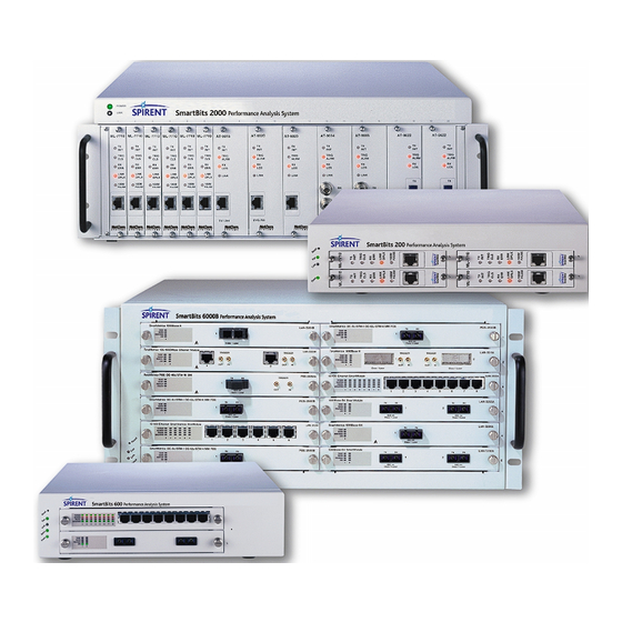
System Architecture In this chapter . . . • SmartBits Chassis Models and Cards..14 • SmartBits-200..15 • SmartBits-2000..15 • SmartBits-600..16 • SmartBits-6000B..16 • Summary of SmartBits Software..17 • Card Architecture..18 • Traffic Generation and Performance Analysis..19 SmartBits System Reference... -
Page 22: Smartbits Chassis Models And Cards
3 All technologies except POS (Ethernet, ATM, Frame Relay, Token Ring). 4 Eth + POS = Fast and Gigabit Ethernet and Packet over SONET (POS). 5 The SMB-10 “slave” chassis is controlled and dependent on an SMB-2000 chassis. SmartBits System Reference... -
Page 23: Smartbits-200
SMB-200 has front panel Fan, Link, and Power LEDs, and a reset switch. The SMB- 2000 has only Power and Link LEDs and no reset switch. • SMB-200 SmartBits System is the portable version of the SMB-2000 chassis. • SMB-200 has a 4-slot chassis vs. SMB-2000 which has a 20-slot chassis. -
Page 24: Smartbits-10
Each chassis holds up to 12 modules that can support up to 24 Gigabit Ethernet ports, 96 10/100 Mbps Ethernet ports, 12 POS (Packet over SONET) ports, 12 SmartMetrics Gigabit Ethernet ports, or a mixture of these port types. Figure 2-4. SmartBits-6000B Chassis SmartBits System Reference... -
Page 25: Summary Of Smartbits Software
AST II VAST SmartCableModem Test ScriptCenter SmartTCP 1 Appropriate cards for an application vary according to application. Refer to Chapter 5, “Core Software Applications,” , and Chapter 6, “Optional Applications,” for program descriptions. 2 ML05710 USB mode available. SmartBits System Reference... -
Page 26: Card Architecture
TCP/IP Layers 2 through 5, with an emphasis on high speed technologies and advanced testing methodologies implemented via a onboard Pentium/Linux processor Figure 2-5. Where Card Architecture Types Function For a list of cards supporting each application, refer to the chapter on each card type. SmartBits System Reference... -
Page 27: Traffic Generation And Performance Analysis
SmartFlow described below. • SmartFlow. A Spirent Communications term that is a superset of the above definition of “flow.” A SmartFlow may include a single flow of traffic from point A to point B, and may transmit many-to-one, one-to-many, or a set of different flows from either receiving or transmitting ports for statistical analysis. -
Page 28: Traditional Cards And Traffic
Alternate Streams. In Traditional mode, there is an additional, simple Alternate stream that can be defined, that is inserted in the traffic pattern at specified intervals and can be used to simulate management frames. Gigabit Ethernet Cards have two Alternate streams. SmartBits System Reference... - Page 29 ATM type. Similar to the Traditional cards, ATM cards have additional capabilities, ranging from one tracked trigger per port to over 2,000 triggers per port, depending on the card. For more information, refer to Chapter 11, “ATM Cards,”. SmartBits System Reference...
- Page 30 PVCs/SVCs No signature field. ATM-2 Up to 2048 Cards PVCs/SVCs 1 In SmartWindow, SmartLib, and SmartApplications. In SmartSignaling, up to 8.38 million VCCs can be generated for tests. See other applications for maximum PVCs/SVCs supported. SmartBits System Reference...
-
Page 31: Smartmetrics Cards And Traffic
• Frame sequence number. • Transmit timestamp. Important: If enabled, the Signature field overwrites the last 18 bytes of data at the end of payload of each frame, therefore, do not insert significant data into that area. SmartBits System Reference... - Page 32 For basic rate calculation, refer to the SmartLib User Guide. For a quick, easy GUI representation, you can also use the SmartWindow Rate/Load calculator, available in the Transmit Setup for the POS-6500 and LAN-6201 cards. SmartBits System Reference...
- Page 33 Channelized E1 2,048 and PPP WN-3445A WAN FR Flows Scheduler Channelized DS3 2,048 and PPP 1 The maximum number of streams distributed across up to 1022 PVCs (Frame Relay) or across the number of available channels (PPP). SmartBits System Reference...
-
Page 34: Terametrics Cards And Traffic
Measures per-port performance, IP flow performance, and QoS. • Supports full wire rate data plane testing, control plane testing, and application layer testing. • On-board Linux/Pentium-based processing power, allowing top-to-bottom testing of the most sophisticated network systems. SmartBits System Reference... -
Page 35: Chapter 3 Multiple Users Accessing A Chassis
Multiple Users Accessing a Chassis In this chapter . . . • Requirements for Multi-User Operation..28 • Preparing for Multi-User Operation..29 • How Does the Multi-User Feature Work?..29 SmartBits System Reference... -
Page 36: Requirements For Multi-User Operation
Help > About command. If you have an older chassis, you can retrofit your SmartBits chassis by purchasing the hardware upgrade and sending the chassis to Spirent Communications to install the SMB-2000 multi-user compliant backplane and controller firmware. –... -
Page 37: Preparing For Multi-User Operation
While connected to a multi-user chassis, users can reserve available ports and: • run multiple applications • run multiple instances of a program that supports multi-users • run any other Spirent Communications application SmartBits System Reference... - Page 38 All connected SmartBits chassis must be multi-user ready in order to perform the multi-user function. • If you are working in a multi-user SmartBits chassis environment, you cannot test or configure a port if you do not have ownership of that port. SmartBits System Reference...
-
Page 39: In Smartwindow, With Smb-600 And Smb-6000B Multi-Users
Therefore, even if no cards are reserved by you and all cards have been released or reserved by other users, the chassis link will remain until disconnected. SmartBits System Reference... - Page 40 You will see this dialog box. Select the Refresh, Release or Reserve command as needed. Note: When connected to the SMB-600 chassis, the SmartWindow interface adjusts to display the more compact hardware platform. Each slot represents a module. SmartBits System Reference...
-
Page 41: In Smartwindow, With Smb-2000
Click SMB Group Start Figure 3-3. Multi-user Compliant SMB-2000 Main Menu ß Follow these steps to access SmartWindow using a SMB-2000: To refresh, release, or reserve a single SmartCard, right-click on it. You will see this dialog box. SmartBits System Reference... -
Page 42: In Smartflow
Ports in chassis that are not multi-user enable Available for you or someone else to reserve Someone else reserved this port since you connected You reserved this port. It is not available to anyone else until you release it SmartBits System Reference... - Page 43 You can either select another port, omit that port from the test, or wait until the port is again available. Release a Port for Another User to Reserve Select the Card Setup tab. Click the box in the Multiuser field for the port. That will clear the check mark. SmartBits System Reference...
-
Page 44: In Smartcablemodem Test
SmartBits or since the last Refresh. It is possible for a port to be reserved by another user in the time between the last refresh and your attempt to configure or use the port. To see the latest, most current ownership status of all ports, select the Actions > Refresh command. SmartBits System Reference... -
Page 45: In Smartxdsl
Setup menu Preferences window or already reserved by another user. While the chassis is reserved, it is not available to another user or to any other Spirent Communications application. When you connect to a multi-user chassis, only cards available (not in use by another user) AND appropriate to the specific set of tests, will be displayed in Available Trunk and Access ports columns. - Page 46 While it is reserved, it is not available to anyone else either using another copy of SmartxDSL or any other Spirent Communications application. If any user fails to release ports presented to him, any subsequent users will access the SmartBits chassis and see no ports as available.
-
Page 47: Chapter 4 Maintenance And Upgrade Procedures
Maintenance and Upgrade Procedures In this chapter . . . • Downloading New Firmware..40 • Adding Cards to a SmartBits Chassis..40 • Changing Chassis Timeout..41 • Changing Chassis Fuses..41 SmartBits System Reference... -
Page 48: Downloading New Firmware
You can download firmware for chassis and for individual cards from our website at http://www.netcomsystems.com/support/softwareupdates.asp or from a Spirent Communications CD. If you download from the website, be sure to obtain a password from Spirent Communications Technical Support to open the files. There are two firmware download programs available for SmartBits chassis: •... -
Page 49: Changing Chassis Timeout
It houses the power switch, fuse holder and a universal 3-wire instrument power cord jack. Replacement fuses are metric. Chassis Fuse Amperage SmartBits 200 F2.0 Amp, 250V, fast action SmartBits 20003.15 3.15 Amp, 250V, fast action SmartBits System Reference... - Page 50 Note: The SMB-200 employs a compact AC/DC power supply that provides a minimum of 100-watt DC output at +5 volt. An additional DC/DC switching module is installed on the backplane to provide a +12 volt DC output, that is used both by cooling fans and the plug-in SmartCards. SmartBits System Reference...
-
Page 51: Chapter 5 Core Software Applications
Core Software Applications In This Chapter . . . • Overview of Core Applications..44 • SmartWindow..45 • SmartLib..47 • SmartApplications..48 SmartBits System Reference... -
Page 52: Overview Of Core Applications
Hardware and PC requirements for the applications listed above can be found in the individual manual for each application. To run SmartLib or script-based programs on a SparcStation or other UNIX platform, please consult the SmartLib User Guide or the appropriate script user document for the latest requirements. SmartBits System Reference... -
Page 53: Smartwindow
• RFC 2544, Benchmarking Methodology for Network Interconnect Devices. • To use a suite of custom tests to verify your design, improve product quality, perform Test Objectives: low-volume production and repair testing, and perform competitive marketing analysis. SmartBits System Reference... - Page 54 • ATM VCC T. Note: Refer to the SmartWindow User Guide for an explanation of these tests. • Sequence Tracking. SmartMetrics- Based Results: • Latency over Time. • Latency per Stream. • Latency Distribution. • Raw Tags. SmartBits System Reference...
-
Page 55: Smartlib
WAN E1 and T1 (Frame Relay V.35 and RS-45). – IP, TCP, PPP, UDP, and IPX. – Token Ring 4 MB and 16 MB systems. – VG/AnyLan in Ethernet models. • Operating Systems Supported: – Microsoft Windows 98, 20. – UNIX (Linux and Solaris). SmartBits System Reference... -
Page 56: Smartapplications
Test ATM with LANE SVC, Classical IP (per RFC-1577) PVC/SVC, or SNAP (per RFC-1483) PVC/SVC traffic. • Test at layer 2, or specify network addresses and test at layer 3. • Run tests individually, or use automatic mode to run tests automatically. • Test full or half duplex. SmartBits System Reference... - Page 57 Proper cabling. • An IBM or compatible Pentium PC running Windows 98 or NT. • An RS-232 modem cable or an RJ-45 straight-through cable (Ethernet) and a 10 Mbps half duplex Ethernet controller card (in the PC). SmartBits System Reference...
- Page 58 SmartBits System Reference...
-
Page 59: Chapter 6 Optional Applications
Note: The applications described in this chapter may be purchased in addition to the core software. Each of these applications requires a separate licensing text file known as a key file. This file is provided on a 3.5” diskette with the program, or is available through Spirent Communications Technical Support. SmartBits System Reference... -
Page 60: Special Feature Support
SmartBits chassis for the following required version levels: • Multi-chassis feature support. Chassis firmware version 6.08 and higher • Multi-user feature support. Chassis firmware version 6.50 and higher • SMB-200 support. Chassis firmware version 6.12 and higher SmartBits System Reference... -
Page 61: Local Multiple Chassis Applications
SmartTCP 1.10 and higher SCMT 1.10 and higher VAST 2.10 and higher ScriptCenter 1.00 and higher Chapter 5, “Core Software 1 This applications information can be found in Applications” , and is not included in this chapter. SmartBits System Reference... -
Page 62: Remote Multiple Chassis With Gps
GPS. Refer to Table 6-2 on page 54 for a list of applications, and consult your Spirent Communications sales representative for additional applications information. Table 6-2. Applicable Chassis and Applications for Synchronized Chassis via GPS... -
Page 63: Smartsignaling
This test measures the maximum number of call setups and teardowns a device under test can process per second without failure. Call Capacity This tests the number of concurrent virtual circuit connections that can be established and maintained by the device under test. SmartBits System Reference... -
Page 64: Smartmulticastip
IGMP join request is sent to the DUT. • SmartCard ports to receive the last multicast frame once an IGMP join request is sent to the DUT. Mixed Class Throughput Determines the DUTs throughput when transmitting both multicast and unicast traffic. SmartBits System Reference... -
Page 65: Smartxdsl
ML-7710, 10/100 Base-TX, SmartMetrics. • ML-5710A, 10 Base Ethernet, USB, SmartMetrics. Refer to the SmartxDSL API Manual located at http://www.netcomsystems.com/support/ documentation.asp for a complete description of the tests available. Table 6-5 gives a brief description of these tests. SmartBits System Reference... - Page 66 This test measures loss of ATM cells. In this test each frame equals one cell in size.The test measures the difference between frames transmitted and frames received. This test is applicable only to ATM end-to- end operation, and operates in upstream, downstream, and bi-directional test modes. SmartBits System Reference...
-
Page 67: Smartflow
LAN-3301A/3311A, 10/100/1G Copper, GBIC, Terametrics. – POS-3500B, OC12/OC3, SmartMetrics. – POS-3500Bs, OC12/OC3, Single Mode, SmartMetrics. – POS-3502A, OC-3, SmartMetrics. – POS-3502As, OC-3, Single Mode, SmartMetrics. – POS-3504As, OC-48c, Single Mode, SmartMetrics. – POS-3505As, OC-48c, Single Mode, TeraMetrics. SmartBits System Reference... - Page 68 DUT’s load tolerance limits. Latency Snap Shot Measures the latency of each received frame, for a specified number of frames in flows and groups of flows sent through a device. SmartBits System Reference...
-
Page 69: Smartvoipqos
Compared to the Latency test, this test can provide a finer view of latency behavior at the DUTs load tolerance limits. SmartBits System Reference... -
Page 70: Advanced Switch Tests For Ethernet (Ast Ii)
LAN-3201As, 1000 Base Ethernet, Single Mode, SmartMetrics – LAN-3201B, GBIC, SmartMetrics – LAN-3710A, 10 Gigabit Ethernet, RMII/SMII Refer to the SmartAPI for Advanced Switch Tests II located at http://www.netcomsystems.com/support/documentation.asp for a complete description of the tests available. SmartBits System Reference... - Page 71 Determines the overall forwarding performance of the DUT/SUT including frame loss rate, throughput, and forwarding rate using different traffic distributions. Forward Pressure Determines how the DUT/SUT handles forward pressure on a port-by-port basis. The test utilizes burst-time mode. SmartBits System Reference...
-
Page 72: Virtual Lan Advanced Switch Tests (Vast)
ARP requests sent. VLAN by MAC Address VLAN by Port Determines throughput, accuracy, packet loss, and VLAN by Protocol flooding when sending multiple streams of traffic to a VLAN. VLAN by Subnet Address VLAN by Tag SmartBits System Reference... -
Page 73: Smartcablemodem Test
Received data is monitored and a record is kept of the following: • Transmitting port number. • Transmitting stream number. • Total number of frames received. • Number of frames received in sequence. • Lagging (extremely late) frames received. • Frames expected, but not received. SmartBits System Reference... - Page 74 This test records the unfiltered tags. Results of the test are presented for viewing in a table format that can be saved to a file in tab delimited format. SmartBits System Reference...
-
Page 75: Scriptcenter
LAN-3201As, 1000-Base Ethernet, SmartMetrics, Multi Mode. – LAN-3201B, SmartMetrics, GBIC. – LAN-3710A, 10 Gigabit Ethernet, RMII/SMII. – POS-3500B, POS OC-12/OC-3. – POS-3500Bs, POS OC-12/OC-3, Single Mode. – POS-3502A, POS OC-3. – POS 3502As, POS OC-3, Single Mode. SmartBits System Reference... -
Page 76: Smarttcp
DUT can support. Session Rate Measures the rate of TCP session setup and teardown through the DUT. Connection Teardown Rate Measures the rate at which the DUT closes the TCP connections. SmartBits System Reference... -
Page 77: Chapter 7 Sample Test Topologies
Sample Test Topologies In this chapter . . . • Sample Devices and Networks to Test..70 SmartBits System Reference... -
Page 78: Sample Devices And Networks To Test
Permanent (PVC). The PVC is a point-to-point connection that is similar to a leased data line. It is dedicated and used over long periods of time. • Multicast (MVC). The MVC is a connection between groups of users, who can use both SVCs and PVCs. SmartBits System Reference... -
Page 79: Testing Packet Over Sonet Routers
Testing real POS Router performance with SmartMetrics: Per-flow Frame loss, Latency, Latency and Sequence, and Latency Distribution tracking. • Testing core and edge router capabilities through a fully integrated array of Spirent SmartMetrics cards. Refer to the SmartWindow User Guide located at http://www.netcomsystems.com/... -
Page 80: Testing Gigabit Routers
– Latency and Sequence. – Latency Distribution tracking. • Testing core and edge router capabilities through a fully integrated array of Spirent SmartMetrics cards. Refer to the SmartWindow User Guide located at http://www.netcomsystems.com/ support/documentation.asp for detailed information regarding applicable tests and features. -
Page 81: Testing Atm
Virtual Path Indicator (VPI) and the Virtual Channel Indicator (VCI) fields in a Cell Header that accompanies every cell. http://www.netcomsystems.com/ Refer to the SmartWindow User Guide located at support/documentation.asp for detailed information regarding applicable tests and features. SmartBits System Reference... - Page 82 SmartBits System Reference...
-
Page 83: Chapter 8 Chassis Specifications
Chassis Specifications In This Chapter . . . • SMB-200/2000 Specifications..76 • SMB-6000/6000B Specifications..78 SmartBits System Reference... -
Page 84: Smb-200/2000 Specifications
Max number of ports: SMB-200 – 4. SMB-2000 – 20. Front Panel LEDs: SMB-200 – Power, Link, and Fan. SMB-2000 – Power and Link. Back Panel LEDs: SMB-200 – Link and Activity. SMB-2000 – Link and Activity. SmartBits System Reference... -
Page 85: Smb-10
SMB-10 The SMB-10 is a 20-slot chassis which connects to and expands the capacity of a SMB- 2000. This chassis is totally dependent on the controller of the connecting SMB-2000, and is referred to as a “slave.” SmartBits System Reference... -
Page 86: Smb-6000/6000B Specifications
SMB-600 – 2 • SMB-6000B – 12 • Max number of ports SMB-600 – 16 • SMB-6000B – 96 Front Panel LEDs Power, Fan, Link, and Status. Back Panel LEDs Activity/Collision, Link/Error, Full/Half Duplex, and 10/100 Ethernet. SmartBits System Reference... - Page 87 For detailed cable, connector, and accessory information, please refer to Appendix E, “SMB-600/6000B Cables and Connectors” Appendix F, “SMB- 200/2000 Cables and Connectors” • Other helpful topics located in include “Downloading New Firmware” on page 40, and “Changing Chassis Timeout” on page 41 SmartBits System Reference...
- Page 88 SmartBits System Reference...
-
Page 89: Chapter 9 Ethernet Cards
SmartCards and Modules..94 • GX Series SmartCards..96 • LAN Series Modules..98 • ML Series SmartCards..110 • ST Series SmartCards..112 • SX Series SmartCards..113 • Standard Ethernet Features..114 • Gigabit Frame Rate Calculation..130 • Gigabit Ethernet Testing, Clock Tolerance..132 SmartBits System Reference... -
Page 90: Ethernet Applications
SX-7405 VLAN and Capture SX-7410 10/100 Base-TX (MII) SX-7410B 10/100 Base-TX (RJ-45) SX-7411 100 Base-FX Fiber VLAN/Data Capture Ethernet Cards Used in SMB-600/6000B Chassis LAN-3100A 10/100 Mbps Full/Half Duplex LAN-3101A 10/100 Mbps 12-port LAN-3111A 100 Base-FX Fiber SmartBits System Reference... - Page 91 1 Supports 10 Mbps Ethernet mode only. 2 A firmware upgrade is required to support this application version. 3 When ordering, specify the wavelength required measured in nanometers; i.e., 1310 nm for LAN-3710AL or 1550 nm for LAN-3710AE. SmartBits System Reference...
-
Page 92: Minimum/Maximum Frame Lengths For Each Card
8191 8191 Capture Ethernet Cards Used in SMB-600/6000B Chassis LAN-3100A 10/100 Mbps Full/Half Duplex 16,384 LAN-3101A 10/100 Mbps Copper RJ-45 1600 LAN-3150A 10/100 Mbps Full/Half Duplex 16,384 (RMII/SMII) LAN-3200A 1000 Mbps Full Duplex Fiber 2048 Multi Mode SmartBits System Reference... - Page 93 1000 Mbps Single Mode 2048 LAN-3201B 1000 Mbps GBIC 2048 LAN-3300A 10/100/1000 Mbps GBIC LAN-3301A 10/100/1000 Mbps Copper 16,384 16,384 LAN-3310A 1000 Mbps Single/Multi Mode GBIC LAN-3311A 10/100/1000 Mbps Single/Multi 16,384 16,384 Mode Fiber LAN-3710A 10G Base (LR/ER) Ethernet SmartBits System Reference...
-
Page 94: Feature Summary Of 10/100 Mbps Cards
Collisions Detected Flow Control Traffic Rates > wire speed > wire speed > wire speed # Ports per Card 1 Allows SmartMetrics tracking and histograms. 2 Only works in half duplex mode; not applicable to full duplex. SmartBits System Reference... - Page 95 > wire speed > wire speed # Ports per Card 1 USB/Ethernet 16 (6100) 12 (6101) 8 (3100) 6 (3101) 2 (3150) 1 Allows SmartMetrics tracking and histograms. 2 Only works in half duplex; not applicable to full duplex SmartBits System Reference...
- Page 96 FST_CAPTURE_INFO (applies to both the ML-7710 and the LAN-3101A). (None of the other "FST_CAPTURE_n" commands can be used with either the ML- 7710 or the LAN-3101A.) • The following command is used to show data integrity errors: ETH_EXTENDED_COUNTER_INFO and a parameter u64RxDataIntegrityErrors (applies to LAN-3101A). SmartBits System Reference...
- Page 97 2.68 sec Increments 400 ns 40 ns 400 ns 40 ns Duplex Mode Full/Half Full/Half SmartMetrics Latency resolution + 100 ns + 100 ns Max # streams per port 1000 1000 Alternate Streams Max # Flows per stream SmartBits System Reference...
- Page 98 Trigger 1,Trigger 2; Trigger 1 or Trigger 2; Trigger 1 and Trigger 2. Collisions Detected (Half duplex only) Flow Control Traffic Rates > wire speed > wire speed 1 Allows SmartMetrics tracking and histograms. SmartBits System Reference...
-
Page 99: Feature Summary Of Gigabit Cards
Jumbo Carry Chaining, Added Rx Card Insertion Gen./Valid. Gen./Valid. Distribution Frames and Bit Masking Triggers GX-1405B GX-1405Bs GX-1420B GX-1421A LAN-3201B LAN-3300A LAN-3301A LAN-3310A LAN-3311A LAN-3710A 1 With management frames and cut-through channel only (not in SmartMetrics streams). SmartBits System Reference... - Page 100 32 ns VLAN Tagging Collisions Detected Flow Control Traffic Rates > wire speed > wire speed # Ports per Card 1 Allows SmartMetrics tests and histograms. 2 Only works in half duplex mode; not applicable to full duplex. SmartBits System Reference...
- Page 101 8 ns 8 ns VLAN Tagging Collisions Detected Flow Control Traffic Rates > wire speed > wire speed > wire speed > wire speed > wire speed # Ports per Card 1 Allows SmartMetrics tests and histograms. SmartBits System Reference...
-
Page 102: Smartcards And Modules
Flashes Red once for each bad CRC detected in receive frames. Not receiving. LINK/ Green Full duplex with valid link. DPLX Yellow Half duplex with valid link (SX-7410). No link detected. Half duplex, with valid link (ST-6410). SmartBits System Reference... - Page 103 Displays amber for autonegotiated 100 Mbps. TRIG (GX-1405 and GX-1420B) PAUSE Green Receiving trigger frames. Yellow Receiving PAUSE frames. No trigger or pause events. 100M (SX-7410 and ML-7710) PAUSE Green 100 Base-TX operation. Yellow Receiving PAUSE frames. 10 Base-T operation. SmartBits System Reference...
-
Page 104: Gx Series Smartcards
Generates good and errored traffic. Millions of IP Flows generated in Generates oversized and undersized hardware. frames (0–2,048 bytes). Generates oversized and undersized frames (20–2,048 bytes). ARP reply analysis. Ping generation. VLAN Tag generation. SmartBits System Reference... - Page 105 One GX-1405B or AT-9xxx SmartCard, or • Two SX-/ML-xxxx, WN-xxxx, or TR-8405 SmartCards. Warning: Failure to follow these rules may result in blown fuses within the SMB-2000 chassis. To replace a blown fuse, refer to Chapter 4, “Maintenance and Upgrade Procedures.” SmartBits System Reference...
-
Page 106: Lan Series Modules
A packet-based traffic generator to test performance, conformance, and interoperability of Test Objective: devices based on industry standard RFCs testing. Upstream traffic and throughput testing can be performed by using a LAN-3200A module Interoperability: in combination with the LAN-3100A module. SmartBits System Reference... - Page 107 Table 9-1, “Ethernet Cards Used in Applications,” on page • Table 9-2, “Min/Max Frame Lengths in Bytes for Ethernet Cards,” on page • Table 9-4, “10/100 Mbps Ethernet Cards – Feature Set for SmartMetrics Cards,” on page SmartBits System Reference...
-
Page 108: Lan-3101A Modules
Table 9-2, “Min/Max Frame Lengths in Bytes for Ethernet Cards,” on page • Table 9-4, “10/100 Mbps Ethernet Cards – Feature Set for SmartMetrics Cards,” on page • Table 9-5, “Comparison of ML-7710 and LAN-3101A Cards,” on page SmartBits System Reference... -
Page 109: Lan-3111A Module
Raw Tags. • Frame Variation. • Interface: Specifications: – IEEE 802.3 serie3s 100 Base-FX specifications. – 1300nm multi-mode fiber. • Connector type: LC-Fiber. • Line Rate: 100 Mbps, full-duplex only. • Port Density: 6 ports per LAN-3111A module. SmartBits System Reference... - Page 110 Full line rate (100 Mbps) capture and analysis. – Frame length: 18–2,006 bytes. – Frame selection: entire frame only. – 6500 frame capture buffer for frames. – Pre-capture filtering on: CRC errors, undersize, oversize, data integrity errors, alignment errors, received triggers, or all. SmartBits System Reference...
- Page 111 – Pings (requests Rx and Tx; replies Rx and Tx. – ARPs (requests Rx and Tx; replies Rx and Tx. • One slot in an SMB-600 or SMB-6000B chassis. Requirements: • A Pentium PC running Windows 98/2000/NT. SmartBits System Reference...
-
Page 112: Lan-3201X Series Modules
• Generates and responds to 802.3x flow control commands. • Data Integrity Check optionally detects Bit Errors in Layer 3 forwarding devices. • 1MB capture buffer enables logging and exporting of filtered events to protocol analysis equipment. SmartBits System Reference... - Page 113 Table 9-1, “Ethernet Cards Used in Applications, ” on page • Table 9-2, “Min/Max Frame Lengths in Bytes for Ethernet Cards,” on page • Table 9-6, “Advanced Gigabit Features,” on page • Table 9-8, “SMB-600/6000B Gigabit Ethernet Cards — Feature Set Summary,” on page SmartBits System Reference...
-
Page 114: Lan-3300 Series Modules
Qualify 10/100/1000 Mbps networking devices during development, quality assurance, and final regression testing. • Perform stress and negative testing by injecting errored traffic. • Perform comparative analysis of 10/100/1000 Mbps networking devices and re- qualify after firmware upgrades. SmartBits System Reference... - Page 115 Table 9-1, “Ethernet Cards Used in Applications,” on page • Table 9-2, “Min/Max Frame Lengths in Bytes for Ethernet Cards,” on page • Table 9-6, “Advanced Gigabit Features,” on page • Table 9-8, “SMB-600/6000B Gigabit Ethernet Cards — Feature Set Summary,” on page SmartBits System Reference...
-
Page 116: Lan-3710A Module
• Data Integrity Check detects bit errors in Layer 3 forwarding devices. • 4 Mbps capture buffer enables the logging and exporting of filtered events to protocol analysis equipment. • IP index increments with each frame transmitted. SmartBits System Reference... - Page 117 10 Gigabit Ethernet IEEE 802.3ae standard. Specification LAN-3710AL LAN-3710AE Number of ports per module Reach Single mode – Single mode – from 2-10 kilometers from 2-40 kilometers Wavelength 1310 nm 1550 nm SmartBits System Reference...
-
Page 118: Ml Series Smartcards
Table 9-1, “Ethernet Cards Used in Applications,” on page • Table 9-2, “Min/Max Frame Lengths in Bytes for Ethernet Cards,” on page • Table 9-4, “10/100 Mbps Ethernet Cards – Feature Set for SmartMetrics Cards,” on page SmartBits System Reference... -
Page 119: Ml-7710/7711 Smartcards
Table 9-2, “Min/Max Frame Lengths in Bytes for Ethernet Cards,” on page • Table 9-4, “10/100 Mbps Ethernet Cards – Feature Set for SmartMetrics Cards,” on page • Table 9-5, “Comparison of ML-7710 and LAN-3101A Cards,” on page SmartBits System Reference... -
Page 120: St Series Smartcards
Additional features can be found in the following tables: Additional Features: • Table 9-2, “Min/Max Frame Lengths in Bytes for Ethernet Cards,” on page • Table 9-3, “10/100 Mbps Ethernet Cards – Feature Set for ST and SX Cards,” on page SmartBits System Reference... -
Page 121: Sx Series Smartcards
Table 9-1, “Ethernet Cards Used in Applications,” on page • Table 9-2, “Min/Max Frame Lengths in Bytes for Ethernet Cards,” on page • Table 9-3, “10/100 Mbps Ethernet Cards – Feature Set for ST and SX Cards,” on page SmartBits System Reference... -
Page 122: Standard Ethernet Features
......VFD 3 Size ....... . . SmartBits System Reference... - Page 123 Background because it may be over written by VFD (Variable Field Data) resources on the SmartCard/module. The default pattern is all zeros. The patterns 8-Fs, 8-0s and 8-0s, 8-Fs refer to bytes of 0x00 or 0xFF. The resulting pattern for 8-Fs, 8-0s is: 0xFF,FF,FF,FF,FF,FF,FF,FF,00,00,00,00,00,00,00,00… SmartBits System Reference...
- Page 124 The signature field and CRC are 22 bytes (continues the pattern from the payload data). After the IP header, signature field, and CRC are written into the frame, the payload data maintains the offset of the pattern based on the initial background fill pattern. SmartBits System Reference...
- Page 125 Frame capture, namely the recording of frame contents by the receiving SmartBits card, is stopped upon user request or when the capture buffer has been depleted. The maximum number of frames that can be captured depends on frame size and the available buffer size. SmartBits System Reference...
- Page 126 VLAN Tag Pause IP Frame IP Checksum IP Checksum Interframe Interframe Interframe Interframe Interframe Interframe Subminimum Subminimum Subminimum Subminimum Subminimum Subminimum Data Integrity Error Note: Management frames such ARP/ICMP/IGMP frames are not given a special status code. SmartBits System Reference...
- Page 127 Packet contains a SmartMetrics signature field (Layer 3). Packet met trigger criteria. Captures frames with receive triggers defined in the Trigger Setup window. Undersize packet or (runt) frame, less than 64 bytes. Packet contains a VLAN tag (for ML-7710 only). SmartBits System Reference...
- Page 128 All SmartBits Ethernet cards can generate CRC-errored frames. Data Integrity Check The receiving card checks the frame contents for data integrity errors (CRC-16 errors) and counts the frames with them. Duplex Mode Available modes: full (unidirectional) and/or half (bidirectional). SmartBits System Reference...
-
Page 129: Flow Control
Frame Size = 8 × N bits (N = number of bytes) Speed = 10,000,000 (Ethernet), 100,000,000 (Fast Ethernet), 1,000,000,000 (Gigabit Ethernet) in bits per second (bps) • Formula: Maximum Frame Rate = Speed ÷ (Gap + Preamble + Frame Size) SmartBits System Reference... - Page 130 Each transmit mode essentially sets the inter-frame gap (IFG) timer value between frames. When bursty-oriented transmission styles are in use, the gap timer is loaded with an alternate value, called the inter-burst gap (IBG), between bursts. SmartBits System Reference...
-
Page 131: Rate Calculation
Megabit card, there are 100 million bit times per second. Interframe Gap Based on Load% Frame Rate = [100%load/(frame size + min frame gap)] * desired load then InterFrame Gap = [100% load – (frame size * frame rate)]/frame rate SmartBits System Reference... - Page 132 A jumbo frame is an Ethernet frame with a length between 1519 and 9018 bytes with valid CRC, or a length between 1523 and 9022 bytes with valid CRC and VLAN tag. If jumbo frame reception is not enabled, jumbo frames are counted as oversize frames. SmartBits System Reference...
- Page 133 The probability density function distribution may have up to 10 peaks. Each peak has a gaussian distribution, with independently controllable width (standard deviation), mean value (the length where the maximum probability occurs) and height relative to other peaks. SmartBits System Reference...
-
Page 134: Measurements
• Sequence Tracking. • Latency over Time. • Latency per Stream. • Latency Distribution. • ARP Exchange Time. • Raw Packet Tags. • Frame Variation. Note: Additional display types are also offered for advanced applications. SmartBits System Reference... -
Page 135: Raw Packet Tags Measurement
No filtering is performed on stream tags received. Up to 130,000 packets are stored and sent to the application. The user can take the data in the delta column, paste it into a spreadsheet, and determine standard deviation and latency variation. SmartBits System Reference... -
Page 136: Speed
129, this is labeled Mode N (errored trigger frames NOT counted) cards: – ML-5710. – ML-7710. – ML-7711. – LAN-3101A. Figure 9-4 on page 129 describes how triggers and errored traffic are displayed in counters available in SmartBits applications. SmartBits System Reference... - Page 137 9. CRC, Alignment error + Dribble bit error => CRC counters 10. CRC, Alignment error, Dribble bit error, and Symbol errors => CRC counters Note: The Symbol error trigger is available only in SmartLib. Figure 9-4. Legend for Error Frames and Counters SmartBits System Reference...
-
Page 138: Gigabit Frame Rate Calculation
Conversely, you can calculate the frame rate from the Payload Capacity Utilization as follows: (Max. frame rate) = Max. Payload Capacity Utilization (Bps) / (frame size + 12 (inter-frame gap) + 8 (minimum preamble) + 4 (CRC) SmartBits System Reference... - Page 139 The frame rates for the LAN-320x modules fall into four categories, each with an independent clock source: • Frame Rate • Clock Rate • InterFrameTime • Calculated Rate Refer to the SmartWindow User Guide, located at http://www.netcomsystems.com/ support/documentation.asp for detailed information regarding applicable tests and features. SmartBits System Reference...
-
Page 140: Gigabit Ethernet Testing, Clock Tolerance
MAC layer before buffering or adding management information, such as time stamps, we assume that it is buffering 64 bytes for each 64 byte packet. That would be 19,047 bytes per second for this port pair. To keep this simple, we assume unidirectional traffic and all SmartBits System Reference... - Page 141 (output faster by 9.976ppm) In test 4, reversed the direction of unidirectional The test failed in 10.5 seconds when: traffic without changing the cable connections. input = plus 10.16ppm output = plus 2.64ppm (output slower by 7.52ppm) SmartBits System Reference...
- Page 142 If the total buffer space is statically assigned per port, tests similar to the Back-to-Back test would fail the device faster if there are large clock tolerances differences from port to port. SmartBits System Reference...
-
Page 143: Packet Over Sonet Modules
Packet over SONET Modules In this chapter . . . • Packet over SONET (POS) Applications..136 • Packet over SONET (POS) Module Types..137 • Packet over SONET (POS) LEDs..138 • POS-3500/3502 Series Modules..139 • POS-3504As Module..141 SmartBits System Reference... -
Page 144: Packet Over Sonet (Pos) Applications
Description POS Modules Used in SMB-600/6000B Chassis POS-3500B 10/100 Mbps Full/Half Duplex POS-3500Bs 10/100 Mbps 12-port POS-3502A 1000 Base Full Duplex, Multi-mode POS-3502As 10/100 Mbps Full/Half Duplex POS-3504As 10/100 Mbps 12-port POS-3505As 1000 Base Full Duplex, Multi-mode SmartBits System Reference... -
Page 145: Packet Over Sonet (Pos) Module Types
This module includes the SmartMetrics functionality plus dedicated hardware that supports a Pentium/Linux based open-architecture platform. This supported platform allows the integration of Spirent Communications software with other powerful third party programs, to provide optimum testing systems. In addition, the on-board processing power of the TeraMetrics module enables total traffic generation and measurement in excess of 1 terabit per second. -
Page 146: Packet Over Sonet (Pos) Leds
Loss of Frame condition exists. Green (flashing) "Management" frame is received. Yellow Loss of signal (optical signal) condition exists. TRIG/LOS (POS-3505As) Green When a triggered frame is received. Yellow A loss of signal (optical signal) condition exists. SmartBits System Reference... -
Page 147: Pos-3500/3502 Series Modules
Packet over SONET/SDH routers. Tests high-speed inter-networking between POS and either Gigabit-Ethernet, Fast- Ethernet, ATM, or Frame Relay devices via Spirent Communications unique SmartMetrics Layer 2, 3, and higher tests. Simulates the millions of client and server sessions required to fully test POS systems. - Page 148 Mbps, user- controlled controlled Multi-mode – Single-mode – Multi-mode – Single-mode – Reach up to 500m up to 15km up to 500m up to 15km SONET or SDH SONET or SDH SONET or SDH SONET or SDH Framing SmartBits System Reference...
-
Page 149: Pos-3504As Module
• User-selectable Frame Check Sequence (FCS) of 16- or 32-bit. • IP traffic encapsulated over PPP (as per RFC 1662) or over Cisco’s HDLC with Ethertype. • MPLS with static labels enables functional testing of routing hardware. SmartBits System Reference... - Page 150 Additional analysis capabilities include data integrity checking of payload and IP header checksum verification. One port per POS-3504As module. Specifications: Line Rate: 2.4 Gbps. Wavelength: 1300 nm. Reach: Single mode – up to 15km. Framing: SONET or SDH. SmartBits System Reference...
-
Page 151: Chapter 11 Atm Cards
ATM ARP Parameters..159 • ATM Line Parameters..160 Using ATM SmartCards, frame-level functional testing is supported for Ethernet LAN-to- ATM, ATM-to-Ethernet LAN, and ATM-to-ATM. Note: In all latency measurements, only the first frame in the stream is measured. SmartBits System Reference... -
Page 152: Atm Applications
Multi Mode Fiber OC-3c/STM-1 AT-9155C (155 Mbps) (4 MB RAM) Single Mode Fiber OC-3c/STM-1 AT-9155Cs (155 Mbps) 1300 nm Multi Mode Fiber OC-12c/STM-4 AT-9622 (622 Mbps) 1300 nm Single Mode Fiber OC-12c/STM-4 AT-9622s (622 Mbps) 1300 nm SmartBits System Reference... -
Page 153: Atm Introduction
Standard traffic contract parameters are user-definable per VCC based on: – Constant Bit Rate (CBR): PCR, CDVT. – Unspecified Bit Rate (UBR): PCR • Supports frame latency measuerments with 100 ns timestamp resolution. Fully compatible with legacy LAN SmartCards. SmartBits System Reference... -
Page 154: Atm Leds
Alarm Event. Flickers for line- or section-level SONET alarms. TRIG (AT-9155C and AT-9622) ALARM Green Trigger Event indication. Flickers for each trigger. Alarm Event. Flickers for any SONET alarm. RX LOS Yellow Loss of signal (optical signal) condition exists. SmartBits System Reference... - Page 155 = –19.5 dBm Mbps fiber 1300nm typical = –17 dBm max = –14 dBm AT-9622s OC-12c/STM-4 622 2,048 8,388,606 SC multimode min = –15 dBm Mbps fiber 1300nm typical = –11 dBm max = –8 dBm SmartBits System Reference...
-
Page 156: Atm Smartcards
Supports LANE testing with up to 8 LECs. • Supports up to 800 calls per second per port in SmartSignaling (AT-9045B). • Supports up to 8,388,606 simultaneous virtual circuit connections per port utilizing a 40-port ATM test suite. SmartBits System Reference... - Page 157 Supports SmartxDSL version 1.01 and higher. Special Features • 2K streams (compared to 256). • Per VC triggers plus multi-burst transmit mode capabilities. • AAL5 CRC-32 error generation. • PPP support. Table 11-3 on page 147. Specifications: SmartBits System Reference...
-
Page 158: Atm Cell Header
SmartWindow calculates the HEC byte for the specified header internally. For the AT-9622/9622s OC-12c SmartCard, enter only idle cells with the VPI/VCI fields set to zeroes. SmartBits System Reference... -
Page 159: Atm Alarms
LOP. Loss of Pointer is set whenever an invalid SONET pointer value is read from the H1 and H2 bytes for eight consecutive frames. The Loss of Pointer is cleared when any valid pointer value, including AIS, is received for 3 consecutive frames. SmartBits System Reference... - Page 160 0.25% zero content) is detected. • Idle. For AT-9045B only: Idle code signal detected by the DS3 framer. A DS3 idle cell is a 1100… payload with valid framing and parity, equal X-bits, and all C-bits set to 0. SmartBits System Reference...
- Page 161 B8ZS. For AT-9015 DS1 only. The absence of B8ZS encoding is detected in the frame signal. • EZA. Excess zeros alarm. Use only the B8ZS coding mode for DS1, per the ATM Forum: This bit is set when a string of eight or more consecutive zeros are received. SmartBits System Reference...
- Page 162 204 valid symbols and the counter increases to 7 (maxi- mum value). – When the alarm is in a cleared state (a signal is present), the alarm is asserted again once the counter decreases to 0 (minimum value). The initial counter value is 0. SmartBits System Reference...
-
Page 163: Atm Line Event Statistics
PLCP Bit Interleaved Parity errors. • PLCP FEBE Error. For DS1 PLCP and the E1 PLCP mapping modes only. This counter is active in the DS1 PLCP and the E1 PLCP mapping modes only. SmartBits System Reference... - Page 164 G1 octet of a PLCP frame. Note: The following counters are paused on the AT-9045B SmartCard: • Frame Error. • Parity Error. • C Parity Error. • FEBEs. SmartBits System Reference...
-
Page 165: Atm Ilmi Parameters
Prefix. The 13-byte ATM network prefix. • Set. Selector byte-User defined 1-byte of portion of the 20-byte ATM address used by the end station. • Status. The Status pane with the following fields is display-only, but may be copied: SmartBits System Reference... -
Page 166: Atm Lane Parameters
ELAN Name. The name of an ELAN that you want to join. The name must exactly match (case sensitive) one of the ELAN names specified on the device under test. • MAC Address. The 6-byte MAC address of the LAN Emulation Client on the ATM SmartCard. SmartBits System Reference... -
Page 167: Atm Arp Parameters
ATM ARP Server, you must ensure that: • LMI is up or has already obtained the ATM address of the SmartCard. • SCOP/UNI must be running (i.e. SSCOP in "Data Transfer Ready State", and SAAL in "Connected" state). SmartBits System Reference... -
Page 168: Atm Line Parameters
Disabled – No loopback is used. This is the normal operating mode of the device. – Local – Loops the SmartCard's output back to the SmartCard's input. – Remote – Loops the SmartCard's input back to the SmartCard's output. SmartBits System Reference... - Page 169 Line Framing. This field applies only to the AT-9015 SmartCard. Select the framing mode for the physical layer. Possible values: – D4 – Uses D4 line framing (not supported by the ATM Forum). – ESF – Uses Extended Super Frame line framing. SmartBits System Reference...
- Page 170 (the first four bytes of the header) that is transmitted when no data cells are being transmitted. SmartWindow calculates the HEC byte for the specified header internally. For the AT-9622 OC-12c SmartCard, enter only idle cells with the VPI/VCI fields set to zeroes. SmartBits System Reference...
-
Page 171: Wan Cards
WAN Cards In this chapter . . . • WAN Applications..164 • WAN LEDs..166 • WN-3405, WN-3415, WN-3420A SmartCards..168 • WN-3441A, WN-3442A, WN-3445A SmartCards..169 SmartBits System Reference... -
Page 172: Wan Applications
Note: Throughout this manual, the term “card” may be used interchangeably to represent either SmartCards (SMB-200/2000), or modules (SMB-600/6000B). Table 12-1. WAN Cards Used in Applications Card/ Module Description WAN Cards Used in SMB-200/2000 Chassis WN-3405 6 Mbps V.35 WN-3415 WN-3420A T1 FR/PPP WN-3441A WN-3442A E1 FR/PPP SmartBits System Reference... -
Page 173: Feature Summary Of Wan Cards
Over FR (RFC Over FR (RFC 1490) or PPP (RFC 1490) or PPP (RFC 1490) or PPP (RFC 1490) or PPP (RFC 1490) or PPP (RFC 1662) 1662) 1662) 1662) 1662) 1 Requires external Balun for impedance matching. SmartBits System Reference... -
Page 174: Wan Leds
The LINK LED indicates the status of all four ports. If all ports are linked correctly, this LED is off. If any of the four ports is not linked correctly, the LED displays Red. To determine port-specific status and events, check the individual port LEDs (see Table 12-3 on page 167). SmartBits System Reference... - Page 175 Flashes if one or more ports are receiving frames with errors. Yellow Flashes if one or more ports are receiving data while one or more ports are receiving frames with errors, or the card is initializing. No data is being received. SmartBits System Reference...
-
Page 176: Wn-3405, Wn-3415, Wn-3420A Smartcards
Re-qualify WAN switches and access devices after firmware upgrades. • These tests provides 2-byte time resolution with granularity of 100-nanosecond Features: resolution. • SmartMetrics tests. Sequence Tracking plus Latency, Latency Over Time, and Raw Packet Tag Information. SmartBits System Reference... -
Page 177: Wn-3441A, Wn-3442A, Wn-3445A Smartcards
Port link is down. Port link is up but not transmitting data. RX/ERR Green Flashes once for each frame received on this port. Flashes once for each frame received with an error on this port. No data is being received. SmartBits System Reference... - Page 178 Chapter 12: WAN Cards WN-3441A, WN-3442A, WN-3445A SmartCards TX/LNK Port LEDs RX/ERR Port LEDs Figure 12-1. Location of Port LEDs on a WN-3442A SmartCard SmartBits System Reference...
-
Page 179: Token Ring Cards
Token Ring Cards In this chapter . . . • Token Ring Applications..172 • Token Ring LEDs..173 • Token Ring Counters..174 • TR-8405 Token Ring 4/16Mbps SmartCard..175 • Token Ring Operational Detail..176 • Ring Protocols Used by the TR-8405..185 SmartBits System Reference... -
Page 180: Token Ring Applications
Note: Throughout this manual, the term “card” may be used interchangeably to represent either SmartCards (SMB-200/2000), or modules (SMB-600/6000B). Table 13-1. Token Ring Card Used in Applications Card/ Module Description Token Ring Cards Used in SMB-200/2000 Chassis TR-8405 4/16 Mbps Token Ring SmartBits System Reference... -
Page 181: Token Ring Leds
CRC. 16M 4M Green 16 Mbps (steady on LED operation) 4 Mbps (steady on LED operation) Yellow ST PORT Green Station Emulation (steady on LED operation) MAU (Port) Emulation (steady on LED Yellow operation) SmartBits System Reference... -
Page 182: Token Ring Counters
Lost Frame Receiver Congestion. • Frame Copied, Frequency Errors. • Token Errors. • Purge Events. • Beacons. • Claim Events. • Insertions. All undisplayed counters are continuously active and can be chosen at any time without affecting their contents. SmartBits System Reference... -
Page 183: Tr-8405 Token Ring 4/16Mbps Smartcard
Packet Length. From 1 to 18006 bytes fixed, or random varying from 18 to 18191 bytes (4096 bytes for 4 Mbps). The random packet length function allows the user to control the range. The upper limit of the range is twice the length entered in the Fixed Length field. SmartBits System Reference... -
Page 184: Token Ring Operational Detail
• VFD3. An arbitrary sequence of bytes that can be placed anywhere in the frame. This sequence can be specified for a set of one or more frames, the only limitation being SmartBits System Reference... - Page 185 Frame Control (FC) byte. The Frame Control byte is set from either an applications control or by overwriting it with the first byte of a VFD3 pattern. This byte is preset to 0x40 when the optional LLC field is enabled. SmartBits System Reference...
- Page 186 Gap figures are expressed internally in bit clock time and are computed from the supplied value in nanoseconds by the card firmware. The interframe gap has a minimum value of one bit clock time. SmartBits System Reference...
- Page 187 60-byte frames the accuracy level is one bad frame in a group of about 300. The Single Step frame always has the specified error in it. It will even have the error when the Percentage figure is zero. SmartBits System Reference...
- Page 188 All counts are automatically computed as a rate because counts are accumulated on a second by second basis before being added to the count totals. Not all of these rate counts are meaningful to the user so only a subset of the rates are displayed. SmartBits System Reference...
- Page 189 Purge Events Number of times Ring Purge MAC frames detected. Claim Events Number of times Claim MAC frames detected. Beacon Events Number of times Beacon MAC frames detected. Insertions Number of Request Initialization MAC frames. SmartBits System Reference...
- Page 190 Although this process is sufficient for most applications envisaged for the card, users may need finer control for their tests. The TR card has provision to control the operation of the card through the TRA serial command and its corresponding TRAdvancedControl function in the programming library. SmartBits System Reference...
- Page 191 Bits 2 and 1 control Fiber Key generation (see section below for a description of this facility). When set to 0 - default - the key is generated as needed, when set to 1 the key is not generated, when set to 2 the key is generated only once. SmartBits System Reference...
- Page 192 If the heartbeat fails, then the TR-8405 will time out the connection and restart the join process. The concentrator can force the TR-8405 back to normal Token Ring operation at any time by issuing a Claim MAC frame. SmartBits System Reference...
-
Page 193: Ring Protocols Used By The Tr-8405
Receiving a favorable reply the unit will start transmitting Hearbeat frames at regular intervals. The TR-8405 only implements a subset of the protocols and FSMs, enough to get and maintain a connection to a typical unit. Errors or denial responses are dealt with by timeouts. SmartBits System Reference... - Page 194 The program will display the download progress as a percentage of the file transferred. The user can stop the download at any time by issuing a Control/Break; however, the Smartbits will probably need to be power cycled to get it communicating to the application or utility. SmartBits System Reference...
- Page 195 The card parameters are set to a default state after completing a firmware load. This state has the cards set as 16MBits/sec stations, half duplex, connecting to the ring at startup with the operating parameters set to continuous transmit, 64 byte frames, one frame per token with the headers set on. SmartBits System Reference...
- Page 196 SmartBits System Reference...
-
Page 197: Chapter 14 Fibre Channel Cards
Fibre Channel Cards In this chapter... • Fibre Channel Modules..190 • FBC-3601A, FBC-3602A Modules..191 • Fibre Channel LEDs..193 SmartBits System Reference... -
Page 198: Fibre Channel Modules
Quality of Service (QoS) metrics are analyzed on streams to determine the actual performance of Fibre Channel switches, hubs, and fabrics. All test functionality is also available via the SmartLib API, allowing for test case automation using a variety of programming languages, including C, C++, or Tcl. SmartBits System Reference... -
Page 199: Fbc-3601A, Fbc-3602A Modules
Arbitrary stream sequencing enables the mixing of various frame rates. • Per-port statistics provide counters for transmitted frames, received frames, received bytes, and received CRC errors. • 16MB capture buffer enables the logging and exporting of filtered events to external protocol analysis equipment. SmartBits System Reference... - Page 200 • Two independent ports per card. Specifications: • Full line-rate traffic generation and analysis at 1 Gbps (FBC-3601A) and 1 and 2 Gbps (FBC-3602A). • Industry standard GBIC interface allows users to change the physical interface connection. SmartBits System Reference...
-
Page 201: Fibre Channel Leds
Receiving CRC errors. Not receiving. TRIG/OSERR Green Receiving trigger. Receiving encoding errors. Yellow No OS error or trigger. LINK/Speed Green Link up @ 2 Gbps. No GBIC link – loss of signal. Link up @ 1 Gbps. SmartBits System Reference... - Page 202 SmartBits System Reference...
-
Page 203: Rfcs Supported With Smartbits Applications
TCP/UDP port numbers) • SmartMulticastIP RFC 2432, Terminology for IP Multicast Benchmarking • RFC 2236, Internet Group Management Protocol, Version 2 • RFC 2113, IP Router Alert Option • RFC 1112, Host Extensions for IP Multicasting SmartBits System Reference... - Page 204 ITU-T Recommendation Q.2110 SmartxDSL PPP over ATM support with RFC 2364 PPP over AAL5 RFC 1661 The Point-to-Point Protocol (PPP). Updated by RFC 2153. RFC 1662 PPP in HDLC-like Framing RFC 1332 The PPP Internet Protocol Control Protocol (IPCP) SmartBits System Reference...
- Page 205 Note: This discussion is not applicable to WAN, POS, or ATM that use traffic descriptors and other techniques to adjust the transmission between devices. In this appendix . . . • Gigabit Fiber Auto Negotiation..198 • 10/100/1000Mbps Copper Ethernet Auto Negotiation..199 • Summary of MII Registers and Bit Definitions..204 SmartBits System Reference...
-
Page 206: Gigabit Fiber Auto Negotiation
IEEE standard document 802.3z. The PCS (Physical Coding Sublayer) contains the 8b/10b encoder/decoder, device synchronization process and the auto negotiation process. Spirent Communications has implemented the PCS sub-layer in its FPGA logic, as well as through the on-board microprocessor. -
Page 207: 10/100/1000Mbps Copper Ethernet Auto Negotiation
(normally performed when the link initializes), or to force speed and duplex settings to desired values for the interface. • Status Register (Register 1). This read-only register defines the capabilities of the PHY as currently set, as well as some latched conditions. SmartBits System Reference... - Page 208 Note: The same MII register (Register 4) that advertises speed and duplex for auto negotiation advertises a port's flow-control capability. Thus, the bit for flow control is set at the same time as the bits for the speed/duplex options. SmartBits System Reference...
-
Page 209: Auto Negotiation Priorities
Auto negotiation is best viewed as one phase of the link initialization and verification process. The following sections focus on the effects of having AN enabled or disabled, as well as on how AN is handled in Spirent Communications applications. SmartBits System Reference... - Page 210 However, different capabilities can be advertised and negotiated by modifying the MII registers, then restarting the test. Spirent Communications test applications such as SmartApplications, AST II, SmartFlow, and SmartMulticastIP also offer the following three configuration options for auto negotiation: •...
-
Page 211: Operation After The Auto Negotiation Protocol Completes
After the flow-control, speed, and duplex settings have been set (and/or negotiated), but before the test is started, SmartBits verifies that a communication link has been established. Once this is done, the application begins the selected test. SmartBits System Reference... -
Page 212: Summary Of Mii Registers And Bit Definitions
Auto Negotiation Advertisement Auto Negotiation Link Partner Base Page Ability Auto Negotiation Expansion Auto Negotiation Next Page Transmit Auto Negotiation Link Partner Received Next Page 1000BASE-T2 Control Register 1000BASE-T2 Status Register 11-14 Reserved Extended Status Vendor Specific 17-31 Reserved SmartBits System Reference... - Page 213 1 = Full duplex 0 = Half duplex Collision Test 1 = Enable COL signal test 0 = Disable COL signal test Speed selection Bit 6 Bit 13 Meaning Reserved 1000Mbps 100Mbps 10Mbps Reserved Write as 0, ignore on Read SmartBits System Reference...
- Page 214 0 = PHY is not able to perform AN Link Status 2 = Will latch until register is read; records down condition even if link comes back up until read. 1 = Link is up 0 = Link is down SmartBits System Reference...
- Page 215 Used by AN to indicate that the device has received its Link Partner’s Link Code Word. Remote Fault Remote fault information. Technology Ability Reserved Reserved 1 = Flow control bit supported 0 = Not supported 100BASE-T4 100BASE-TX Full Duplex 100BASE-TX 10BASE-T Full Duplex 10BASE-T Half Duplex SmartBits System Reference...
- Page 216 1 = Configure PHY as Master during AN (only when Configuration Value Bit 12 = 1) 0 = Configure PHY as Slave during AN (only when Bit 12 = 1) T2_Repeater/DTE Bit 1 = Repeater device port 0 = DTE device Reserved Ignored when read. SmartBits System Reference...
- Page 217 Local Receiver Status 1 = Local receiver OK 0 = Local receiver not OK Remote Receiver 1 = Remote receiver OK Status 0 = Remote receiver not OK 11-8 Reserved Ignored when read. Idle Error Count Idle Error Count SmartBits System Reference...
- Page 218 SmartBits System Reference...
-
Page 219: Certifications
Certifications and EMI Compliance In this appendix... This appendix contains the following topics: • Certifications..212 • SmartBits Compliance with CE Requirements..213 This appendix list SmartBits certifications and provides technical information on SmartBits systems with respect to Electro-Magnetic Interference (EMI). SmartBits System Reference... -
Page 220: Certifications
Re-orient or re-locate the receiving antenna. • Increase the separation between the equipment and receiver. • Connect the equipment into an outlet on a different circuit that the receiver is connected. • Consult the dealer or an experienced radio/TV technician for help. SmartBits System Reference... -
Page 221: Smartbits Compliance With Ce Requirements
CE directives in order to quantify performance measurements, with the ultimate goal of designing the best possible products in every respect. To obtain the CE Mark declaration of conformity, each Spirent Communications product must pass the following standard tests: •... - Page 222 SmartBits to the LAN or to the PC. Use common sense. For example, a test or control cable laid over the AC power sup- ply of an open DUT will most likely produce faulty measurement results. SmartBits System Reference...
- Page 223 ToS Parameters The following table provides common Type of Service values for reference only. For detailed information refer to RFC 1700 for assigned numbers, and to RFCs 791 and 1349 for ToS and standard IP definition. SmartBits System Reference...
- Page 224 Normal Normal Delay Throughput Reliability Immediate Normal Normal Delay Throughput Reliability Flash Normal Normal Delay Throughput Reliability Flash Override Normal Normal Delay Throughput Reliability CRITIC/ECP Normal Normal Delay Throughput Reliability Internetwork Normal Normal Control Delay Throughput Reliability SmartBits System Reference...
- Page 225 Routine High Normal Delay Throughput Reliability Priority High Normal Delay Throughput Reliability Immediate High Normal Delay Throughput Reliability Flash High Normal Delay Throughput Reliability Flash Override High Normal Delay Throughput Reliability CRITIC/ECP High Normal Delay Throughput Reliability SmartBits System Reference...
- Page 226 Normal High Control Delay Throughput Reliability Routine Normal High Delay Throughput Reliability Priority Normal High Delay Throughput Reliability Immediate Normal High Delay Throughput Reliability Flash Normal High Delay Throughput Reliability Flash Override Normal High Delay Throughput Reliability SmartBits System Reference...
- Page 227 High Control Delay Throughput Reliability Network Normal High High Control Delay Throughput Reliability Routine High High Delay Throughput Reliability Priority High High Delay Throughput Reliability Immediate High High Delay Throughput Reliability Flash High High Delay Throughput Reliability SmartBits System Reference...
- Page 228 Bit 3 Bit 4 Bit 5 Value Precedence Delay Throughput Reliability Flash Override High High Delay Throughput Reliability CRITIC/ECP High High Delay Throughput Reliability Internetwork High High Control Delay Throughput Reliability High High Network Control Delay Throughput Reliability SmartBits System Reference...
-
Page 229: Smb-600/6000 Cables
SMB-600/6000B Cables and Connectors In this appendix . . . • Ethernet Cables..222 • Ethernet Connectors..223 • POS Connectors..226 • Fiber Optic Cable Signals..227 • SmartBits-to-GPS Receiver Interface..229 SmartBits System Reference... -
Page 230: Ethernet Cables
BLUE-WHITE ORANGE ORANGE GREEN GREEN GREEN-WHITE GREEN-WHITE ORANGE-WHITE ORANGE-WHITE BROWN BROWN BROWN-WHITE BROWN-WHITE _____________________________________________________________ Crossover Cable for 10/100/1000 Base Color Color BLUE ORANGE BLUE-WHITE ORANGE-WHITE ORANGE BLUE GREEN BROWN GREEN-WHITE BROWN-WHITE ORANGE-WHITE BLUE-WHITE BROWN GREEN BROWN-WHITE GREEN-WHITE SmartBits System Reference... -
Page 231: Ethernet Connectors
I and O respectively. The J1 and J2 pin structures are exactly the same except for the port numbers (0, 1, 2, 3 for J1; and 4, 5, 6, 7 for J2). SmartBits System Reference... - Page 232 6 MDIO This signal is bidirectional. MDC This is an output signal. For a single eight-port DUT, the above MII management signals from the J2 connector should be used; the corresponding signal at the J1 connector should be ignored. SmartBits System Reference...
- Page 233 Connector type: GBIC. Function Rx Gnd RD+ (Rx Data Out +) RD- (Rx Data Out - ) SD (Rx Signal Detect) TD - (Tx Data In - ) TD + (Tx Data In + ) Tx Gnd ____________________________________________________________ SmartBits System Reference...
-
Page 234: Pos Connectors
TRD 3+ TRD 3 - ____________________________________________________________ POS Connectors POS-3500B, POS-3502A Connector Connector Type: Fiber, SC duplex to SC duplex, multi mode. ____________________________________________________________ POS-3500Bs, POS-3502As, POS-3504As, POS-3505As Connector Connector Type: Fiber, SC duplex to SC duplex, single mode. ____________________________________________________________ SmartBits System Reference... -
Page 235: Fiber Optic Cable Signals
Multi-mode fiber: 62.5/125 microns (um), 0.275 NA graded-index POS-3500B multimode fiber POS-3502A Transmitter Performance Min. Typical. Max. Optical Outputt Power, dBm- -20.00 -18.00 -14.00 Receive Performance Receiver Sensitivity, P -26.00 -28.00 Max. Input Optical Power, Pmax -14.00 -12.00 SmartBits System Reference... -
Page 236: Single-Mode Sc Duplex To Sc Duplex
1293 1310 1334 for ∆λ ≤ 4.0 nm Receiver Performance: Min. Typical. Max. Receiver Sensitivity, P -19.00 -22.00 – dBm Max. Input Optical Power, Pmax -3.00 -1.0 – dBm Wavelength of operation λ 1100 – 1600 nm SmartBits System Reference... -
Page 237: Smartbits-To-Gps Receiver Interface
The serial (AUX) port on the rear panel of the SmartBits chassis connects to the GPS Receiver’s I/O RS-232C serial interface port via the following modem cable supplied in the GPS kit. SmartBits P/N 240-0006-001(CC-906) Cable SmartBits GPS Receiver RS-232 RS-232 (9-pin) (25-pin) DB-25 DB-9 Male/Female Male/Female (DTE) (DCE) SmartBits System Reference... - Page 238 SmartBits System Reference...
-
Page 239: Smb-200/2000 Cables/Connectors
In this appendix . . . • Ethernet Cables..232 • Ethernet Connectors..233 • Token Ring Cable and Connector..238 • WAN Cables and Connectors..239 • ATM Cables and Connectors..241 • Fiber Optic Cable Signals..244 • SmartBits-to-GPS Receiver Interface..246 SmartBits System Reference... -
Page 240: Ethernet Cables
ORANGE-WHITE ORANGE-WHITE BROWN BROWN BROWN-WHITE BROWN-WHITE _____________________________________________________________ Crossover Cable for 10/100/1000 Base Used with: ML-7710, SX-7410, ST-6410, and GX-1420B Color Color BLUE ORANGE BLUE-WHITE ORANGE-WHITE ORANGE BLUE GREEN BROWN GREEN-WHITE BROWN-WHITE ORANGE-WHITE BLUE-WHITE BROWN GREEN BROWN-WHITE GREEN-WHITE SmartBits System Reference... -
Page 241: Ethernet Connectors
The GX-1421A has one female 80-pin connector. The DUT should have the corresponding 80-pin female connector, and is connected to the GX-1421A by using the 12-inch cables that is supplied and recommended by Spirent Communications. Table 1 on page 234 shows the 80-pin connector pin assignment for SMII and RMII. - Page 242 R_CLK+/– and R_SYNC+/–. These two LVDS input pairs should be the output of 65LVDS31 drivers on the DUT. These signals must be supplied to LAN-3150A via J2. 4 RESET This low active output can be used as PHY hardware reset signal. 5 DNC Do not connect. 6 MDIO This signal is bidirectional. MDC This is an output signal. SmartBits System Reference...
- Page 243 TRD 1- TRD 3+ TRD 3 - _____________________________________________________________ ST-6410, ML-5710, ML-7710, SX-7410 Connector Connector type: RJ-45 female Signal Transmit+ Transmit - Receive + Not Connected Not Connected Receive - Not Connected Not Connected (or Shield for STP) _____________________________________________________________ SmartBits System Reference...
- Page 244 Green Ground Black _____________________________________________________________ SE-6205 Connector Connector type: DB-15-S female Signal Signal Collision Shield Collision - Collision + Transmit - Transmit+ Transmit Shield Receive Shield Receive - Receive + Power Power Return Power Shield Reserved Reserved Reserved SmartBits System Reference...
- Page 245 0 to +5 volts. Use this pinout to determine how to wire the connector on the ribbon cable to an external piece of test equipment: Signal Transmit Trigger Receive Trigger Collision TX en CRC Error Rx Dv Alignment Error Spare SmartBits System Reference...
-
Page 246: Token Ring Cable And Connector
BROWN-WHITE ORANGE GREEN GREEN ORANGE GREEN-WHITE ORANGE-WHITE ORANGE-WHITE GREEN-WHITE BROWN BLUE BROWN-WHITE BLUE-WHITE _____________________________________________________________ TR-8405 Connector Connector type: RJ-45 female Signal No Connection No Connection Transmit + Receive + Receive - Transmit - No Connection No Connection SmartBits System Reference... -
Page 247: Wan Cables And Connectors
Twisted Pair #2 Signal J1-4 J2-1 TX TIP Twisted Pair #2 RTN J1-5 J2-2 TX RING _____________________________________________________________ WN-3415, WN-3420 Connector Connector Type: RJ48C or RJ45C Signal RX_RING RX_TIP Not Connected TX_RING TX_TIP Not Connected Not Connected Not Connected SmartBits System Reference... - Page 248 113 (B) SCTE (B) 114 (A) SCT (A) 114 (B) SCT (B) 115 (A) SCR (A) 115 (B) SCR (B) _____________________________________________________________ WN-3445 Cable/Connector Connector Type: BNC (B3ZS Decoding) Cable: SmartBits P/N 620-0217-001, BNC Male to BNC Male SmartBits System Reference...
-
Page 249: Atm Cables And Connectors
Connector Type: RJ-48C for 120-Ohm external unbalanced (require Balun for impedance) _____________________________________________________________ ATM Cables and Connectors AT-9015 Cable T1 straight-through cable _____________________________________________________________ AT-9020 Connector Connector type: RJ-48C female Signal Rx Ring Rx Tip Not Connected Tx Ring Tx Tip Not connected Not connected Not connected _____________________________________________________________ SmartBits System Reference... - Page 250 Not connected Receive + Receive - _____________________________________________________________ AT-9025 Cable Crossover Cable (RJ-45 at each end) Color Color BLUE BLUE BLUE-WHITE BLUE-WHITE ORANGE Not connected GREEN Not connected GREEN-WHITE Not connected ORANGE-WHITE Not connected BROWN BROWN BROWN-WHITE BROWN-WHITE _____________________________________________________________ SmartBits System Reference...
- Page 251 Connector Type: BNC (DS3 Mode, B3ZS Decoding), with 75-Ohm Impedance Cable: SmartBits P/N 620-0217-001, BNC Male to BNC Male _____________________________________________________________ AT-9155C, AT-9622 Connector Connector Type: Fiber, SC Duplex to SC Duplex, Multi-Mode For details on fiber optic signals, please refer to page 244. SmartBits System Reference...
-
Page 252: Fiber Optic Cable Signals
Sensitivity (OCP dtr-1250-SM-L2 850nm) GX-1405 Min. Avg. Max. Transmit = -9.5 Receive Sensitivity (HP part# HFBR 5205 1300nm) AT-9155C Min. Avg. Max. Transmit Receive Sensitivity (HP part# HFBR 5208 1300nm) AT-9622 Min. Avg. Max. Transmit Receive Sensitivity SmartBits System Reference... -
Page 253: Single-Mode Sc Duplex To Sc Duplex
Single-mode fiber signal values (HP HFCT 53D5 1300nm) GX-1405Bs Min. Avg. Max. Transmit -9.5 Receive Sensitivity (HP part# HFCT 5205B 1300nm) AT-9155s Min. Avg. Max. Transmit Receive Sensitivity (HP part# HFCT 5208B 1300nm) AT-9622s Min. Avg. Max. Transmit Receive Sensitivity SmartBits System Reference... -
Page 254: Smartbits-To-Gps Receiver Interface
The serial (AUX) port on the rear panel of the SmartBits chassis connects to the GPS Receiver’s I/O RS-232C serial interface port via the following modem cable supplied in the GPS kit. SmartBits P/N 240-0006-001(CC-906) cable SmartBits GPS Receiver RS-232 RS-232 (9-pin) (25-pin) DB-25 DB-9 Male/Female Male/Female (DTE) (DCE) SmartBits System Reference... - Page 255 This appendix contains the serial port commands that you can send from your PC directly over the serial port connection to a SmartBits chassis via HyperTerminal or an equivalent terminal emulation program: • Overview of the Serial Command Set..248 • Serial Port Command Set..249 SmartBits System Reference...
-
Page 256: Overview Of The Serial Command Set
The SmartBits 200/2000 chassis do not have super user commands or passwords. The SmartBits 600/6000B chassis offer a superuser mode with additional password protection and commands; some of these commands will only be available with SmartAccess, a new SmartBits utility. SmartBits System Reference... -
Page 257: Serial Port Command Set
The following commands apply to all chassis unless otherwise specified. Note: For additional information on how to use SmartAccess, the new security program, please refer to Applications Note #29, SmartAccess, under the Support page at the Spirent Communications website www.spirentcom.com. - Page 258 The User Number is the parameter used to close a user’s connection. Example report: Show Users detects 2 logged in users to report: USER_NUM: IPADDR (TCP) PORT_NUM: CARDS_OWNED: 192.168.103.50 1073 192.168.103.50 1074 SmartBits System Reference...
-
Page 259: Security Commands
(SMB-600/6000B only) . To exit SuperUser mode and exit access to the SuperUser command set. SECURITY <ENABLE | (SMB-600/6000B only). To enable a second level DISABLE > security mechanism and password for use with the new SmartAccess utility. SmartBits System Reference... - Page 260 SECURITY PW (SMB-600/6000B only). To set the security password for use with the SmartAccess utility. This command prompts you for a password SECURITY SAVE (SMB-600/6000B only). To save the security password for use with the SmartAccess utility. SmartBits System Reference...
-
Page 261: Glossary Of Terms
SmartLib; many of these features and terms are used throughout other SmartBits applications as well. For variations on a given feature, please consult the online help at http://www.netcomsystems.com/ or user guide of each application. In this section. . . • Features and Terminology..254 SmartBits System Reference... -
Page 262: Features And Terminology
Class of Service Used to designate a forwarding device as capable of prioritizing data traffic. SmartBits System Reference... - Page 263 LANE 802.3 (LAN Emulation) The ATM Forum LAN Emulation specification provides an environment where the ATM network is enhanced by LAN Emulation Server(s) to behave as a bridged LAN. Stations obtain configuration information from, and register with, a LAN Emulation SmartBits System Reference...
- Page 264 User indication) field is used to transparently transfer CPCS user to user information. (RFC2364). Available only when SmartWindow is connected to a chassis with cards supporting PPP over ATM (AT-9155C and AT-9622, firmware version 3.00 and higher). SmartBits System Reference...
-
Page 265: Reserved For Smartbits
Ownership is indicated visually by color-coded triangular LEDs next to the port ID number, or by color-coded button LEDs next to the port IDs in a reservations listing: Blue triangle LED – card is reserved to you. Green triangle LED – card is available. SmartBits System Reference... - Page 266 (frame-based) and Layer 3 (stream-based) devices as well as higher layer operations. Each multilayer SmartCard can generate multilayer, mixed protocol traffic equivalent to one fully loaded LAN with up to 1000 end-user devices. The single RJ-45 interface can SmartBits System Reference...
-
Page 267: Port Counters For All Smartcards
Events – The number of occurrences of an action (such as transmitting or receiving a frame, collisions, Rx triggers, and CRC errors) since the last time that counter was reset or cleared. • Rates – The number of events per second that the events happen. SmartBits System Reference... - Page 268 In SmartLib or SmartWindow, you can track one or two triggers per receiving SmartCard in any combination (singly and/or together). In SmartWindow, the pattern is defined in the following: • Transmitting SmartCard • Trigger Setup of the receiving SmartCard SmartBits System Reference...
- Page 269 Static. No change frame-to-frame. • Incrementing. Adding one to the value each frame. • Decrementing. Subtracting one from the value each frame. • Random. A random value each frame. The content is defined by the State pull down menu. SmartBits System Reference...
- Page 270 If Random VFDs 1 and 2 are selected on a non-byte boundary, behavior will be normal. Default is Unselected. SmartBits System Reference...
- Page 271 2048 byte VFD3 buffer length. Once the number of packets and the VFD length are chosen, the data contents of the VFD can be modified by pressing the Edit button. A dialog showing the edit buffer is then presented: SmartBits System Reference...
- Page 272 VTEs A term used in SmartWindow and SmartLib applications, VTE (Virtual Transmit Engine) is a SmartBits engine that is fully customizable and generates its own "stream" of data. VTE is synonymous with “stream.” SmartBits System Reference...
-
Page 273: Index
AT-9020 card 155 background alarms 153 ID 257 line event statistics 155 pattern 115 AT-9034 card 156 backoff truncation exponent 254 alarms 152 baud command 250 line event statistics 156 brochures 9 AT-9034B card 148 AT-9045 card 156 SmartBits System Reference... - Page 274 70 core manuals 8 frame sizes, legal Ethernet 122 counters frame transmit modes 122 alignment 115 frames, jumbo 124 CRC errors 120 fuse holder 41 custom editor 257 Cut Through and Store & Forward devices 255 SmartBits System Reference...
- Page 275 (MMFL) 125 lab partners 11 frame length distribution 91 LAN-3100 multi-mode SC duplex fiber cable 227 feature summary 87 multiple chassis LAN-3100A/3200A series modules 98 applications supporting 53 LAN-3101 multi-user feature summary 87 capabilities 29 LAN-3150 LEDs 30 SmartBits System Reference...
- Page 276 128 safety certification 212 ST-6410 Ethernet card 112 sample tests 70 standards supported by SmartBits applications 195 scheduling board 29 stream defined 19 SCMT 65 streams ScriptCenter 67 alternate 115 description 67 standard & alternate 20 SmartBits System Reference...
- Page 277 UNIX programming 259 requirements 44 updates for manuals, software, firmware 9 User Guide related manuals 5 users command 250 VAST program 64 ver command 249 VFD1 262, 263 VFD1 and VFD2 bit level control 262 VFD2 263 SmartBits System Reference...
Need help?
Do you have a question about the SmartBits System and is the answer not in the manual?
Questions and answers