Table of Contents
Advertisement
Quick Links
Advertisement
Table of Contents

Summary of Contents for Carinci Group Magnum 20 Slim
- Page 2 h e a t i n g s y s t e m i n n o v a t i o n s...
-
Page 3: Table Of Contents
TABLE OF CONTENTS Foreword ............................... Page 5 Preliminary warnings ..........................Page 5 Technical specifications and size of the MAGNUM 25 CARINCI Boiler Page 6 Technical specifications and size of the MAGNUM 35 CARINCI Boiler Page 7 Combustion chamber ..........................Page 8 Description of the automatic pellet kit ...................Page 9 Fuel loading tank ............................ - Page 4 Menu ..............................Page 32 Menu Functions ............................Page 32 Change Extractor Power .......................... Page 32 Change Auger Power ..........................Page 32 10.0 Instructions for first Ignition ....................Page 33 10.1 Quality of recommended fuel (pellets) ......................Page 33 10.2 Other recommended fuels .......................... Page 34 10.3 Circulator regulation ..........................
-
Page 5: Foreword
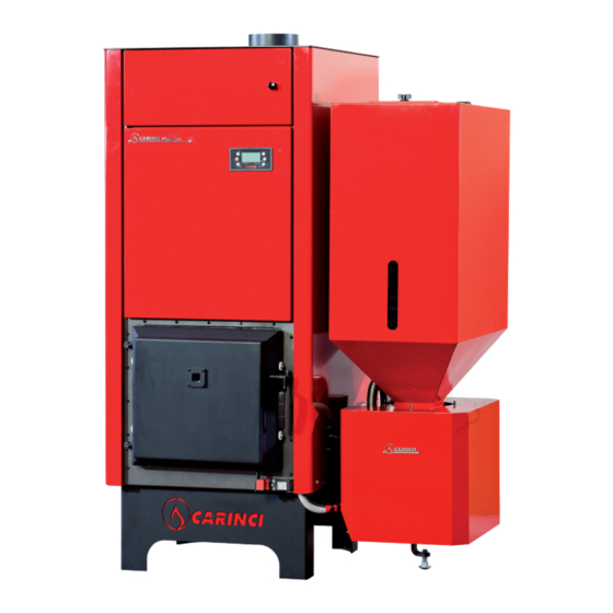
FOREWORD Dear Client, Carinci Group SpA thanks you for choosing the CARINCI MAGNUM BOILER, state-of-the-art technology in biomass heating. - Page 6 TECHNICAL SPECIFICATIONS AND SIZE OF THE MAGNUM 20 slim CARNICI BOILER 1241 1241 1231 All measurements are expressed in millimetres Access door to the combustion chamber Access door to pellet kit Fuel loading Electronic control unit Model SY 250 Access door for heat exchanger cleaning Flue outlet Ø...
- Page 7 TECHNICAL SPECIFICATIONS AND SIZE OF THE MAGNUM 25/35 CARNICI BOILER Magnum 25 - All measurements are expressed in millimetres 1093.5 1090.2 757.5 118.3 327.0 118.3 1093.5 650.0 377.7 118.3 327.0 700.0 893.5 451.0 1094.0 Ø 150 1420.0 1360.0 832.5 757.5 700.0 1399.6 325.0...
-
Page 8: Combustion Chamber
CLEANING THE COMBUSTION CHAMBER The base of the CARINCI MAGNUM Boiler's combustion chamber is made entirely out of blast furnace fire bricks with a high-performance refractoriness of 1620 °C. They are positioned vertically forming a uniform base and walls that are 60 mm thick. -
Page 9: Description Of The Automatic Pellet Kit
DESCRIPTION OF THE AUTOMATIC PELLET KIT The Automatic Kit is made up of a fuel tank, feed motor, conveyor auger, burner and control unit. PELLET LOADING TANK The tank can contain up to maximum 130 Kg of fuel; load using the designated hermetically-sealed door located on the top part of the tank. -
Page 10: Gearmotor With Integrated Frequency Inverter
GEARMOTOR WITH INTEGRATED FREQUENCY INVERTER The Automatic Pellet Kit is made up of a reliable gearmotor unit and a delta-connected, 0.25 kW, 230 V three-phase electric power induction mo- tor, cooled by an internal fan. The group is made up of two different-sized speed reducers, PAM 30 and PAM 50, with a permanent lubrication system thus guaranteeing reliability over time. - Page 11 › Motor potentiometer function › Acceleration/deceleration time with programmable approximation › V/f multi-point feature › Overload to 150% for 60 seconds › 2-cable or 3-cable command › Automatic restart following lack of power supply › Quick start-up Protection features › Protection against overvoltage/undervoltage ›...
-
Page 12: Stainless-Steel Auger
STAINLESS-STEEL AUGER Fuel is carried via a double auger. In between the two augers, there is a 17 cm long fuel flashback arrestor to stop the reverse flow of the flame. IMPORTANT: make sure no objects which could break or irreparably damage the mechanism fall into the tank (e.g. -
Page 13: Burner Maintenance
BURNER MAINTENANCE It is important to check on a weekly basis that the holes of the burner are free from ash or fuel residue in order to ensure the best combustion of the pellets. Even more important is to check that there are no deposits in the lower part of the crucible;... -
Page 14: Flue
FLUE (in compliance with Regulation UNI cig 7129/92) The flue is an important component of a heating system with a wood boiler. Its function is not only to disperse and evac- uate fumes, but also, thanks to an excellent draft, to ensure the Boiler operates correctly given its natural draft function. distance ≤... -
Page 15: Chimney Stack
d) must have smooth walls; e) must have a uniform internal section, preferably circular; must be at least 4 meters high; g) must be at least 50 cm higher than the peak of the roof; h) If required, an incline is allowed (but no higher than 45°); for variations of sections or parts, the functioning of the fumes evacuation system must be inspected with a suitable fluid-dynamic calculating method (UNI 9615);... -
Page 16: Installation Of Carinci Boiler
INSTALLATION OF THE CARINCI BOILER DIAGRAM SHOWING ASSEMBLY OF THE MAGNUM BOILER (according to Regulation EN 10412-2:2009) Thermostatic Mixer Cold water inlet Sanitary hot water 1 2 3 outlet °C DIAGRAM SHOWING ASSEMBLY OF MAGNUM BOILER AND MAGNUM PLUS... - Page 17 DIAGRAM SHOWING ASSEMBLY OF OPEN-VENTED MAGNUM BOILER Safety valves Pressure gauge Temperature gauge Pipe for diaphragm expansion tank [if the diaphragm expansion tank is not sufficent (loss of water at the safety valves due to increase in pressure), it means the quantity of water present in the system is above average;...
- Page 18 DIAGRAM SHOWING ASSEMBLY OF THE 20 SLIM PLUS MAGNUM BOILER (according to Regulation EN 10412-2:2009) DIAGRAM SHOWING ASSEMBLY OF 20 SLIM OPEN-VENTED MAGNUM BOILER...
- Page 19 Safety valves Pressure gauge Diaphragm expansion tank Self-operated thermal discharge valve Input of cold sanitary water (with automatic heat sink function) Output of hot sanitary water (with automatic heat sink function) Circulator inlet plug with an integrated-locking ball valve Circulator Heat outlet M Heat return Automatic filling unit...
-
Page 20: Expansion Tank
INSTALLATION WARNINGS 5.1. EXPANSION TANK (if open-vented) If installed open-vented, the CARINCI MAGNUM Boiler must have a capacity equal to three times the water expansion volume. Expansion percentage at 90 °C = 3/3.5%. MANUAL RESET THERMOSTAT The manual reset thermostat (located at the back of the boiler) is to be used in the event the boiler reaches excessive temperatures (>... -
Page 21: Electrical Connections
5.11 ELECTRICAL CONNECTIONS All electrical connections are located in the junction box under the crankcase cover. In the junction box (Pic. A) remove the top panel (Pic. B) the box contains all the electrical connections required to connect to the local network, the ambient thermostat, the solenoid valve and the AUX connection (connected in series to the gas boiler's ambient thermostat). -
Page 22: Set-Up Of The Carinci Sy 250 Electronic Control Unit
SET-UP OF THE CARINCI SY 250 ELECTRONIC CONTROL UNIT The CARINCI Boiler electronic control unit has a specific handbook with pre-set standard parameters. Here are the specific parameters of the CARINCI SY 250 control unit installed on the CARINCI MAGNUM Boiler. Product: SY 250 TC IDRO INV LCD cod. - Page 23 Product Management Product Code 3506 9999 Password access Secret Menu 9999 Select Language (0=It; 1=En; 2=De; 3=Fr; 4=Es) P 09: Pellet level sensor configuration P 20: Select Pressure Sensor (0=Type A; 1=Type B) 1,399 P 21: Auger Functioning (0=Pause-Work; 1=Invert P36: V2 Output Section (1=Sic.
- Page 24 Ih 25: Thermostat Hysteresis Th 25 °C Th 26: Minimum range of Boiler Thermostat °C Th 27: Maximum range boiler thermostat °C Th 36: AUX Thermostat/Sanitary solenoid valve °C Ih 36: Thermostat Hysteresis Th 36 °C Pressure Sensor Threshold S 01: Minimum threshold mbar 3000 S 08: Maximum threshold...
- Page 25 Delay Intervention Safety T 09: Error signal delay AT1 T 10: Error signal delay AT2 Standby Timer T 11: Delay Exiting Standby T 22: Delay Entering Standby Tank loading timer T 23: Fuel tank filling timer 3600 T 24: Duration of fuel filling inspection 3600 Delay in Auger Activation T 40: delay in activating auger compared to valve...
-
Page 26: Features Of The Residual Current Devices
FEATURES OF THE RESIDUAL CURRENT DEVICES Important warnings before switching on and using CARINCI boilers. It is important to verify the type of residual current device (RCD) installed on the main power supply line, in order to avoid ill-timed black-outs caused by possible incompatibility between the inverter and the residual current device. A suitable residual current device is a type A =>... -
Page 27: Troubleshooting
TROUBLESHOOTING (Electronic control unit Mod. SY 250) PROBLEM ALARM REASON SOLUTION Substitute the circuit Circuit breaker/RCD not breaker/RCD with a suitable The circuit breaker/RCD trips None suitable (See Page 24) Power supply disconnected Connect power supply The terminal box inside the Check that the terminal box control unit has not been has been fully inserted... - Page 28 PROBLEM ALARM REASON SOLUTION The boiler door is open Close the boiler door The writing 'Port' appears on Check that the 'key' has Port the display been inserted correctly The sensor below the door is faulty In the event it is faulty, substitute the whole switch The terminal box of the FLAT cable that joins the control...
- Page 29 PROBLEM ALARM REASON SOLUTION Press WOOD/PELLET in the The WOOD/PELLET button centre for 5 seconds until has not been pressed the writing 'Pellet Switching correctly On' does not appear. Check the power supply is switched on Remove the motor from the gear motor and check it is The motor isn't running working...
- Page 30 PROBLEM ALARM REASON SOLUTION Lower the temperature on The temperature of the the management control The control unit makes a Sound (Beep) thermo-fireplace exceeds unit; once the temperature constant sound 88 °C is below 88 °C, the control unit will stop beeping The terminal box inside the control unit where it is Check that the terminal box...
- Page 31 PROBLEM ALARM REASON SOLUTION Press the Wood/Pellet button Check the correct position of the smoke probe Er03 Low fumes temperature Press the Wood/Pellet button Lower the value of the smoke thermostat (T 09) Press the Wood/Pellet button Er04 Water has overheated Check the boiler thermostat (control unit) Press the Wood/Pellet...
-
Page 32: Buttons
THE CARINCI SY 250 CONTROL PANEL BUTTONS But- Function Description Exit a Menu or Sub-menu On the main screen, press this button to manually load the Auger. To deacti- MANUAL LOADING vate, release the button. Switch from Wood to Pellet and vice versa by pressing the button for 3 sec- WOOD/PELLET onds until you hear the acoustic signal Unblock the system by pressing the button for 3 seconds until you hear the... -
Page 33: Display
DISPLAY Chrono Enable State System Date and Time Maximum number of operating hours achieved Summer-Winter Sat 14:26 Service Error Code Standby Er05 User Power and Combustion Management P2 Auto 65° Pellet 1 Recipe Boiler Thermostat Leds Water Temperature Values displayed on the main screen: • Date and Time • Timer activation mode (D - Day, W - Week, WE - Weekend) • Fan Power... -
Page 34: Menu
MENU The Control Panel has a User Menu which enables the end user to operate the heater according to his/her own needs and a Secret Menu accessible by the Manufacturer who can modify settings, perform tests and check the operational history of the system. -
Page 35: Instructions For First Ignition
50%. The Carinci Group Srl does not take responsibility for the use of poor quality pellets or the use of fuels which have not been recommended. In addition, it does not respond to any subsequent issues with the machinery and the warranty is no longer valid. -
Page 36: Inspections
It is strictly forbidden to use any fuels other than those recommended, whether solid (for example crude pomace, corn, etc.) or liquid. If the boiler suffers any damage due to the use of unsuitable fuel, the CARINCI GROUP takes no responsibility and the warranty is no longer valid. 10.3 REGULATING THE CIRCULATOR AND BALANCING THE SYSTEM a) The circulator must be proportionate to the size of the machinery;... -
Page 37: Recommendations For Use And Routine Maintenance
11.0 RECOMMENDATIONS FOR ROUTINE USE AND MAINTENANCE In the following paragraph, you will find all the useful information for handling a CARINCI boiler. 11.1 CONNECTION TO POWER SUPPLY For correct functioning, the CARINCI Boiler needs to connect to a power supply. The Pellet Kit, fully assembled even in terms of electricity, must simply be connect to a grounded 220 V power supply. -
Page 38: Cleaning The Combustion Chamber
The Pellet Kit is equipped with the following safety devices: • A probe which detects the temperature of the duct carrying the pellets; when very high temperatures are reached, the probe activates the progression of the fuel into the duct towards the burner, preventing flashbacks; • Fumes temperature probe (or unsuccessful ignition): it checks the temperature of the fumes in order to smoke safety... -
Page 39: Extraordinary Maintenance
Customer Service (Tel. +39 0776 812704) or your local The Carinci Group recommends that you do not allow unqualified staff to disassemble the boiler in order to avoid damaging the machinery; if it is necessary to disassemble the boiler and other components, we advise you to follow the procedures listed below very carefully. -
Page 40: Technical Data
12.0 TECHNICAL DATASHEETS Here are all the technical data sheets pertaining to the boilers. CARINCI MAGNUM 20 BOILER Power 30.3 Nominal thermal power 26.6 Direct water power 22.8 Combustion efficiency 87.5 Water output 75.17 Average CO emissions with 10 % of O² 0.017 Average temperature of outlet fumes °C... - Page 41 Directive 89/336/EEC (Electromagnetic Compatibility). N° di identificazione - Identification No. 0189 Emesso da - Issued by Carinci Group S.r.l. I - 03100 - Frosinone (FR) Via Casilina Nord, 251 Tipo di apparecchio - Type of equipment Caldaie a combustibile solido - Heating boilers by solid flue...
-
Page 42: Boilerplates
1,5 bar Ammissibile Massima Temperatura di Lavoro EN 303-5:1999 95 °C Ammissibile Contenuto d’acqua : 112 l Carinci Group SpA : 230 Tensione nominale Via Case Priori, 26 ± 10% 03029 Veroli (FR) Corrente nominale 2,1 A Caldaia CARINCI MAGNUM 25... - Page 43 Directive 89/336/EEC (Electromagnetic Compatibility). N° di identifi cazione - Identifi cation No. 0190 Emesso da - Issued by Carinci Group S.p.A. I - 03029 - Veroli (FR) Via Case Priori, 26 Tipo di apparecchio - Type of equipment Caldaie a combustibile solido - Heating boilers by solid fl...
- Page 44 3 bar Ammissibile Massima Temperatura di Lavoro EN 303-5:1999 90 °C Ammissibile Contenuto d’acqua 95 l Carinci Group SpA Tensione nominale Via Case Priori, 26 ± 10% 03029 Veroli (FR) Corrente nominale Caldaia CARINCI MAGNUM 20 Frequenza nominale 50 Hz...
- Page 46 Our products are guaranteed against manufacturing defects for 2 (two) years from the date of purchase as required under European warranty, only if proof of purchase may be provided in the form of a proof of purchase document and the ‘Protocol for Use’. Within this period, at the discretion of the Carinci Group SpA, the buyer will have the right to repair free of charge, or the replacement of defective parts, excluding glass, bricks and ceramic plates.
- Page 47 PROCEDURAL GUIDE ON IGNITING THE MACHINERY FOR THE FIRST TIME The T.A.C., only when authorised in advance by CARINCI GROUP S.p.A., can perform the 'Set Up' procedure: STAGE 1: Regulating the combustion 30 minutes after ignition, regulate combustion using the designated regulators on the extractor speed (combustion air input) and auger speed (fuel input).
-
Page 48: Warranty
Our products are guaranteed against manufacturing defects for 2 (two) years from the date of purchase as required under European warranty, only if proof of purchase may be provided in the form of a proof of purchase document and the ‘Protocol for Use’. Within this period, at the discretion of the Carinci Group SpA, the buyer will have the right to repair free of charge, or the replacement of defective parts, excluding glass, bricks and ceramic plates. - Page 51 © 2016 Carinci Group S.p.A. Reproduction, also partial, is forbidden - XIV ed. January 2016...
Need help?
Do you have a question about the Magnum 20 Slim and is the answer not in the manual?
Questions and answers