
Related Manuals for Plasmatronics PL20


Summary of Contents for Plasmatronics PL20
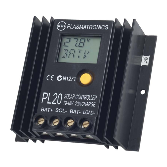
- Page 1 Rev 1.0 25.07.07 PL20N Reference Manual Plasmatronics PL Series Advanced Solar Charge Controller Reference Manual...
-
Page 2: Table Of Contents
PL20N Reference Manual Rev 1.0 25.07.07 Contents Introduction ..................4 Additional Installation Notes ................4 Features ......................5 Overload Protection ..................5 Thermal Protection ..................5 Menus ......................5 1.0 BATV Menu ..................6 The Regulation Cycle ..................6 1.1 BOST (Boost) ................... 6 Returning to Boost state ................ - Page 3 A.0 Appendices .................. 34 A.1 ‘Catch diode‘ protection ................ 34 A.2 Accessories .................... 34 A.3 Specifications on PL20, 40, 60 ..............35 A.3.1 Block Diagram of PL20/40 Hardware .......... 36 A.3.2 Block Diagram of PL60 Hardware ..........36 A.4 Thermal derating ................... 37 A.5 Mechanical Information ................
-
Page 4: Introduction
PL20N Reference Manual Rev 1.0 25.07.07 Introduction Additional Installation Notes Ensure that you have followed the installation Please read the User Guide before reading this instructions on pages 3-5 of the User Guide. The manual. PL can be used for system voltages of up to 48V. In most cases, the User Guide provides all the It is safe to connect the power before setting the information needed for effective installation of... -
Page 5: Features
Rev 1.0 25.07.07 PL20N Reference Manual Features Overload Protection The PL series of solar controllers are exceptionally The PL has over current protection on both the versatile. They give the user unparalleled capability load and charge switches. to adjust the function of the controller and to If the user accidently short circuits the load or monitor the performance of the energy system. -
Page 6: Batv Menu
PL20N Reference Manual Rev 1.0 25.07.07 1.0 BATV Menu BATV The BATV screen, shown at power-up, displays CHRG the real-time battery voltage. BOST EQUL ABSB FLOT LOAD A long push on the BATV screen will display the state of the charge regulation cycle. The Battery Charge Cycle DATA The PL’s sophisticated regulation system is... -
Page 7: Equalise (Optional)
Rev 1.0 25.07.07 PL20N Reference Manual 1.3 ABSB (Absorption) Note: if ETIM is 0, then the Equalise state will be bypassed. If ATIM is 0, then the Absorption state In this state, the PL tries to keep the battery will be bypassed. voltage constant while the last part of the battery On the BOST and FLOT displays, the battery charging occurs. -
Page 8: Chrg Menu
PL20N Reference Manual Rev 1.0 25.07.07 2.0 CHRG Menu where x is the device number. Similarily, for switchblocks the display is SWHx and for shunt adaptors, SHNx. The device number can be CHRG from 1 to 4 for shunt adaptors and from 1 to The CHRG screen gives the real-time total 12 for MPPT or Switchblocks. -
Page 9: Gmod
Rev 1.0 25.07.07 PL20N Reference Manual GSET Mode# Description In the GSET screen, a long push will manually 0. Turn on when battery voltage falls to G change the state of the generator output. The ON for GDEL minutes. Turn off when the GEN indicator at the bottom of the screen is voltage rises to GOFF for GDEL minutes. -
Page 10: Gexd (Generator Exercise)
PL20N Reference Manual Rev 1.0 25.07.07 Generator Control automatic generator exercise function, which will turn on every GEXD days. The number of days For many generators it is possible to control their since the last exercise is shown on the GDAY operation remotely. - Page 11 Rev 1.0 25.07.07 PL20N Reference Manual This direct connection will work if the current flowing through the remote start terminals is less than 300mA. If the current is greater than this, then it will be necessary to use an intermediate ...
-
Page 12: Load Menu
PL20N Reference Manual Rev 1.0 25.07.07 3.0 LOAD Menu LINT External BATV CHRG LOAD LOAD LSET Toggle low battery The LOAD screen gives real-time total load disconnect status on/off current (in Amps). This total is the sum of LOFF Set voltage at which the current flowing through the load terminal load disconnects (LINT) and any external load current. -
Page 13: In Menu
Rev 1.0 25.07.07 PL20N Reference Manual BATV Selecting a load switch Fig. 4A - IN Menu CHRG The low battery disconnect is an internal logical function. To do something other than act as LOAD a warning, it has to be used to control a load External switch. -
Page 14: Data Menu (Retrieving Performance Data)
PL20N Reference Manual Rev 1.0 25.07.07 6.0 DATA Menu changed from the ABSB (Absorption) state to the FLOT (Float) state. (Retrieving Performance Data) This time will only be recorded if the regulator has done a transition into float that day. A time A long-push on DATA, enters the data menu. -
Page 15: Soc (State Of Charge Display)
Rev 1.0 25.07.07 PL20N Reference Manual A long push on the SOC screen will reset the screen. The “A” indicator will disappear. A useful SOC to 100%. memory aid is to consider that “A” stands for “Adjustable” on this screen. The SOC figure should be treated with caution, as there are several reasons that it may be To enable adjustment of settings again, long... -
Page 16: Hist (History Display)
PL20N Reference Manual Rev 1.0 25.07.07 At the start of each day record is the DAY NEXT goes to the next day, BACK goes to the screen. This shows which day’s data you are previous day. The day numbers wrap around looking at (DAY 1 = yesterday, DAY 2 = the day when they reach the end. -
Page 17: Set Menu
Rev 1.0 25.07.07 PL20N Reference Manual 7.0 SET menu Fig. 7A - The SET Menu BATV CHRG The set menu contains most of LOAD the settings which control the operation of the controller. DATA 7.1 TIME TIME VOLT PROG MODE EVNT This screen displays the time on the controller’s clock. -
Page 18: Settings For Program 4
PL20N Reference Manual Rev 1.0 25.07.07 and are not adjustable by the user. For adjustable SET/MODE Setting for program number settings, choose program 4. Parameter The voltage settings are shown correct for 12V LSET operation. For higher voltages, scale these up GSET (eg. -
Page 19: Reg Menu (Customising Regulation Settings)
Rev 1.0 25.07.07 PL20N Reference Manual TIME VOLT PROG MODE EVNT BATV CHRG LOAD Set max boost voltage BMAX Set max equalisation voltage EMAX Set equalisation time ETIM DATA Set # days between eq.cycles EFRQ Set absorbtion voltage ABSV Set absorbtion time ATIM Fig. -
Page 20: Charge Current Limit
PL20N Reference Manual Rev 1.0 25.07.07 Timers: SET/REG/TCMP Selection Summary: The HYST value is also used to start and stop TCMP Function Example Battery the timers associated with the different regulator -5mV°C linear General Purpose - charging states (Boost, Equalise, and Absorption). auto sense use this if in doubt (default) -
Page 21: Connecting A Temperature Sensor
Rev 1.0 25.07.07 PL20N Reference Manual Connecting a Temperature Sensor The temperature sensor should be connected to the T+ and Neoprene T- terminals in the green terminal sponge block (under the lid, above the top left corner of the LCD screen). The sensor wire with the stripe goes to the T–... -
Page 22: Mode Menu (Adjusting Configuration Settings)
PL20N Reference Manual Rev 1.0 25.07.07 MODE BATV TIME VOLT PROG EVNT CHRG LOAD Fig. 7.5A - MODE Menu LSET Set function of LOAD terminal GSET Set function of general purpose terminal (G) DATA ESET Set control of external switches BSET Set function of B input BAT2... - Page 23 Rev 1.0 25.07.07 PL20N Reference Manual SET/MODE/LSET SET/MODE/GSET # Function Terminal is: # Function Terminal is: Low battery on when function Low battery on when function wants disconnect wants to disconnect disconnect to disconnect battery battery Low battery off when function wants Low battery off when function disconnect...
-
Page 24: Shunt Control
PL20N Reference Manual Rev 1.0 25.07.07 Shunt Control will control each external switch block. This is done in the ESET sub menu. A long push on The PL supports either series control, shunt ESET brings up the first switch setting. Short control, or both at the same time. - Page 25 Rev 1.0 25.07.07 PL20N Reference Manual Fuse/Breakers Connect BOOST close to battery B- B- B- S+ B+ L+ terminals Battery Fuse/ Breakers B+ Sense wire (Connect to Battery Negative Terminal) (NOTE: Low Current 'B Sense' wires can be significantly smaller than other wires.) Fig.
-
Page 26: Bat2 - Second Battery Control
PL20N Reference Manual Rev 1.0 25.07.07 Battery 1 Battery 2 BOOST (Primary) (Secondary) Solar Solar B- B- B- S+ B+ L+ B sense input Solar Array Use LOAD or ‘G’ output to switch relay (Wiring for ’G’ output shown) Relay (Relay shown in non-energised state) Fig. -
Page 27: Pwm And Slow Switching
Rev 1.0 25.07.07 PL20N Reference Manual primary battery, and can minimise the amount of short as possible and panel cable pairs together switching required by the relay (which switches over (cable tie). On long wiring runs at higher voltages, each time the primary battery bank voltage falls some damping may be necessary and possibly below FLTV - HYST). -
Page 28: Bcap
PL20N Reference Manual Rev 1.0 25.07.07 by the State of Charge data screen. Long push on or power to an external alarm of some kind. The BCAP to set this value. Set the battery capacity reverse function could be used to turn off a low actually expected as discussed in Section 6.4 priority load when the battery voltage is getting (SOC). -
Page 29: Evnt Menu (Event Control)
Rev 1.0 25.07.07 PL20N Reference Manual 7.6 EVNT Menu (Event Control) Step 2 - Set LSET, GSET or ESET It is necessary to tell the PL which output switch The event controller allows something to happen will be controlled by the Event Controller. For when a set of conditions is met. - Page 30 PL20N Reference Manual Rev 1.0 25.07.07 If the start condition is to be ignored, then select Step 4 STRT=0 so that the start condition is always Select a STOP setting in this table to tell the PL active. what signifies the end of the “event”. SET/EVNT/STRT Selection Summary SET/EVNT/STOP Selection Summary STRT Event starts when...
- Page 31 Rev 1.0 25.07.07 PL20N Reference Manual continue until the time reaches the time you For settings 0 to 7, the low battery disconnect specify in the TIME setting. One use of this (LBD) function will override the EMOD conditon combination of STRT and STOP could be to turn and make EMOD inactive if the load should be a light on between dusk and 11pm.
-
Page 32: Examples
PL20N Reference Manual Rev 1.0 25.07.07 Whether EMOD is on (1) or off (0) if EOFF: Whether STRT is on (1) or off (0) Whether TMOD is on (1) or off (0) if E ON: Whether STOP is on (1) or off (0) EOFF Fig. - Page 33 Rev 1.0 25.07.07 PL20N Reference Manual 3. Pump water if battery is fully charged until tank is full (i.e. switch in tank turns off): STRT STOP TIME EMOD TMOD The STRT condition is always true. The STOP condition becomes true when a float switch in the tank (wired between the PL’s BAT+ and B+ sense terminals) switches off (open), i.e.
-
Page 34: Appendices
PL20N Reference Manual Rev 1.0 25.07.07 A.0 Appendices A.2 Specifications Nominal system voltages 12,24,32,36,48 V A.1 Accessories Maximum voltage BAT+ to There are accessories, which can enhance the BAT- usefulness of the PL controller. Max short term voltage BAT+ to BAT- External Battery Temperature Sensor Maximum voltage SOL+ to (XLT or XLTB) -
Page 35: Specifications On Pl20, 40, 60
Charge Load temperature Current Max Current Max around the PL (°C) PL20 PL40 PL60 PL20 PL40 PL60 40°C 20 A 40A 20 A 7A A.6 Mechanical Information Material: Case: Polycarbonate Heatsink: Anodised Aluminium... -
Page 36: Block Diagram Of Pl20/40 Hardware
PL20N Reference Manual Rev 1.0 25.07.07 B- B- B- S+ B+ L+ Block diagram and terminal layout DISPLAY � ����� ������ TEMPERATURE SENSOR (T+,T-) � BATTERY SENSE (B+ SENSE) ����� LOAD ���������� SERIAL PORT � ‘G’ RELAY ���� ������ SHUNT SHUNT REVERSE FET SWITCH... - Page 37 Rev 1.0 25.07.07 PL20N Reference Manual ����� �� BOOST ����� B- B- B- S+ B+ L+ �� ���� �� ����� ��...
- Page 38 PL20N Reference Manual Rev 1.0 25.07.07...
- Page 39 Rev 1.0 25.07.07 PL20N Reference Manual NOTES...
-
Page 40: Programs 0-3 Menu System
PL20N Reference Manual Rev 1.0 25.07.07 Programs 0-3 Menu System (Programs with fixed settings) Thin arrow = short push Thick arrow = long push (Explained in User Guide p6) Section: BATV BOST EQUL ABSB FLOT CHRG CINT External Note: GSET will not toggle if clock is Toggle function status on/off GSET between 9pm ->... -
Page 41: Program 4 Menu System (For Custom Settings)
Rev 1.0 25.07.07 PL20N Reference Manual Program 4 Menu System (For adjustable settings) Thin arrow = short push Thick arrow = long push (Explained in User Guide p6) Section: BATV BOST EQUL ABSB FLOT CINT External CHRG Note: GSET will not toggle if clock is Toggle function status on/off GSET between 9pm ->... - Page 42 PL20N Reference Manual Rev 1.0 25.07.07 NOTES...
Need help?
Do you have a question about the PL20 and is the answer not in the manual?
Questions and answers