Table of Contents
Advertisement
Advertisement
Table of Contents

Subscribe to Our Youtube Channel
Related Manuals for LTS POE-SW401


Summary of Contents for LTS POE-SW401
- Page 1 POE-SW401/POE-SW801 User Manual...
- Page 2 User Manual About this Manual This Manual is applicable to POE-SW401/POE-SW801. The Manual includes instructions for using and managing the product. Pictures, charts, images and all other information hereinafter are for description and explanation only. The information contained in the Manual is subject to change, without notice, due to firmware updates or other reasons.
-
Page 3: Regulatory Information
User manual of POE-SW401/POE-SW801 Regulatory Information CE Mark Warning This is a Class A product. In a domestic environment, this product may cause radio interference, in which case the user may be required to take adequate measures. NOTE: (1) The manufacturer is not responsible for any radio or TV interference caused by unauthorized modifications to this equipment. -
Page 4: Safety Instruction
User manual of POE-SW401/POE-SW801 Safety Instruction These instructions are intended to ensure that user can use the product correctly to avoid danger or property loss. The precaution measure is divided into “Warnings” and “Cautions” Warnings: Serious injury or death may occur if any of the warnings are neglected. - Page 5 User manual of POE-SW401/POE-SW801 Preventive and Cautionary Tips Before connecting and operating your device, please be advised of the following tips: • Ensure unit is installed in a well-ventilated, dust-free environment. • Unit is designed for indoor use only. •...
- Page 6 User manual of POE-SW401/POE-SW801 Thank you for purchasing our product. If there is any question or request, please do not hesitate to contact dealer. The figures in the manual are for reference only. This manual is applicable to the models listed in the following table.
-
Page 7: Table Of Contents
User manual of POE-SW401/POE-SW801 TABLE OF CONTENTS TABLE OF CONTENTS ..........................6 Chapter 1 Product Overview ......................7 Introduction ............................. 7 Packages Content ..........................7 Front Panel ............................8 Rear Panel ............................9 Chapter 2 Device Installation ......................11 Installation Notes ........................... 11 Safety Alert ............................ -
Page 8: Chapter 1 Product Overview
The whole PoE power output is 58W/120W. With Cat 5 Ethernet cable, power and data can be simultaneously transmitted to APs, IP cameras, IP phones, and other PDs (Power devices). In addition, POE-SW401/POE-SW801 supports Extend mode. With enabling extend mode and Cat 5e Ethernet cable, the transmission distance of data and power can be up to 250m. -
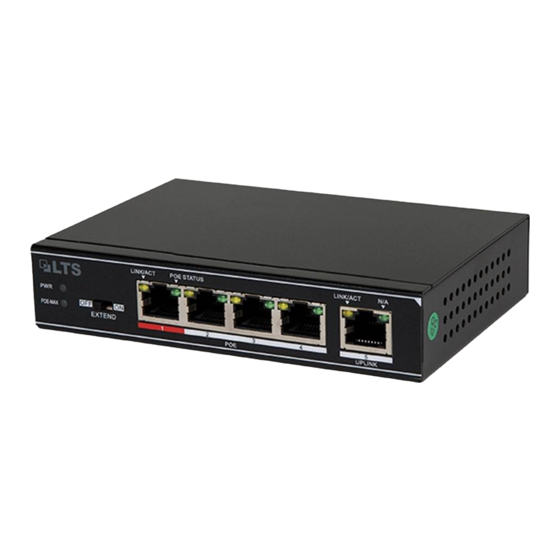
Page 9: Front Panel
User manual of POE-SW401/POE-SW801 1.3 Front Panel Figure 1.1 POE-SW401 Figure 1.2 POE-SW801 Table 1. 1 Description of LEDs Status Description Solid The device is connected to the power supply properly. The device is connected improperly or not connected to the power supply. -
Page 10: Rear Panel
POE-SW801 Note that: 1. Ports 1-2 of POE-SW801 (Port 1 of POE-SW401) are with high priority by default, which take advantage over other ports to process key data or video data. 2. Ports 1-4/8 support IEEE 802.3af and IEEE 802.3at PoE power;... - Page 11 User manual of POE-SW401/POE-SW801 Figure 1 .4 POE-SW801 Power Socket Used for connecting the included power adapter for power supply. Please use the included power adapter to connect the device to power supply. Grounding Terminal Used for connecting the grounding cable for lightning-resisting. The grounding details refer to Section Grounding ...
-
Page 12: Chapter 2 Device Installation
User manual of POE-SW401/POE-SW801 Chapter 2 Device Installation (Here POE-SW801 is taken as an installation guide, which applies to POE-SW401.) 2.1 Installation Notes To guarantee the device long service and your personal safety, please follow notes below. Safety Alert Wear antistatic gloves while installing, and connect the device to power after finishing other installation. -
Page 13: Installation
2.2 Installation The device supports two types of installation: wall-mounting and desktop-mounting. Install your device according to the tools you have. Here POE-SW801 is taken as an installation guide, which applies to POE-SW401. Desktop-mounting Find a flat and stable desktop and place the switch correctly. - Page 14 User manual of POE-SW401/POE-SW801 Step 2: Drill two 6mm diameter holes, about 110mm (POE-SW801) away apart on the same level in the wall. (93mm for POE-SW401) Figure 2.2 Drill holes in the wall Step 3: Insert the expansion screw tubes completely into the holes in the wall with rubber hammer.
-
Page 15: Grounding
User manual of POE-SW401/POE-SW801 2.3 Grounding Grounding is not only important for lightning arresting and anti-interference, but for your own personal safety. Please select the proper method to ground your device. With grounding bar If a grounding bar is available at the installation site, follow steps below to ground the device. - Page 16 User manual of POE-SW401/POE-SW801 Figure 2.6 Ground with an angle steel If both ground bar and the conditions for burying the grounding body are not available, an AC-powered Ethernet switch can be grounded using the PE (Protecting Earth) wire of the AC power supply.
-
Page 17: Chapter 3 Physical Connection
User manual of POE-SW401/POE-SW801 Chapter 3 Physical Connection 3.1 Connect to RJ45 Ports Connect the switch to a remote device with Ethernet cable via RJ45 port. UPLINK is the uplink port. Ports 1-4/8 support IEEE 802.3af and IEEE 802.3at PoE supply, and the PD can be wireless AP, IP phone or IP camera, etc. -
Page 18: Connect To Power Supply
User manual of POE-SW401/POE-SW801 Figure 3.2 Lightning protector connection ① Ethernet cable ③ Grounding terminal ⑤ Lightning protector ② Grounding cable ④ Outdoor cabling 3.3 Connect to Power Supply Please use the included power adapter for power supply. -
Page 19: Appendix Technical Specifications
User manual of POE-SW401/POE-SW801 Appendix Technical Specifications POE-SW401 POE-SW801 Item 10/100Mbps RJ45 ports Interfaces High priority ports Port 1 Ports 1-2 Store-and-forward Supported MAC Table Performance MAC Learning Auto-learning/ Auto-aging Switching Capacity 1Gbps 1.8Gbps PoE standard IEEE 802.3af, IEEE 802.3at...
Need help?
Do you have a question about the POE-SW401 and is the answer not in the manual?
Questions and answers