Table of Contents
Advertisement
Quick Links
Model 2280A
Four Channel Control Module
Hydrogen Sulfide Gas Applications
The information and technical data disclosed in
this document may be used and disseminated
only for the purposes and to the extent
specifically authorized in writing by General
Monitors.
Instruction Manual
General Monitors reserves the right to change
published specifications and designs without
prior notice.
Part No.
Revision
08-07
MAN2280
MAN2280A
D/08-07
Advertisement
Table of Contents
Troubleshooting

Related Manuals for General Monitors MAN2280A

Summary of Contents for General Monitors MAN2280A
- Page 1 General Monitors. Instruction Manual 08-07 General Monitors reserves the right to change published specifications and designs without prior notice. MAN2280 Part No. MAN2280A...
- Page 2 This page intentionally left blank.
-
Page 3: Table Of Contents
Model 2280A Table of Contents FIGURES ............................. V LIST OF TABLES ........................VI INTRODUCTION...........................1 Protection for Life ............................1 Special Warning ............................1 Customer Support ........................2 1.0 BEFORE INSTALLATION ......................3 Differences Between Models 2280A and 2280................3 General Product Description......................3 Controller............................4 Sensor Assembly ........................5 2.0 INSTALLATION ........................6 Location of the Controller......................6 Power Connections ........................6... - Page 4 General Maintenance.......................27 Periodic System Verification ....................27 5.0 TROUBLESHOOTING......................28 General ............................28 Troubleshooting Table ......................28 Fault Codes..........................29 6.0 CUSTOMER SUPPORT .......................30 General Monitors’ Offices ......................30 Other Sources of Help ......................30 7.0 APPENDIX..........................31 Warranty...........................31 Sensor Operating Principle ......................31 General Specifications - Controller ..................33 7.3.1 Mechanical Specifications...................33...
-
Page 5: Figures
Model 2280A Figures Figure 1: Model 2280A ..........................4 Figure 2: Schematic Battery Backup System ....................7 Figure 3: Junction Box Assembly Sensor....................12 Figure 4: Protection Circuit for Relay Contacts ...................14 Figure 5: Common Relay & Rear Terminal Connections ................15 Figure 6: Discrete Relay & Rear Terminal Connections................16 Figure 7: Front Panel Display ........................17 Figure 8: Portable Purge Calibrator......................20 Figure 9: Panel Assembly, Panel Mount –... - Page 6 Model 2280A List of Tables Table 1: Model 2280A Mounting Parts ......................6 Table 2: Sensor Wire Colors ........................10 Table 3: Sensor Cable Colors ........................10 Table 4: Cable Length ..........................11 Table 5: De-Energized Alarm Relay Contacts.....................13 Table 6: Energized Alarm Relay Terminations....................13 Table 7: High Alarm Set Points ........................24 Table 8: Setup Display Options ........................25 Table 9:Troubleshooting Table........................29...
-
Page 7: Introduction
Special care must be taken when wiring the system, to ensure that only the connection points are touched. General Monitors cautions, as with all equipment of this type, that high levels or long exposure to certain atmospheres will “degrade” the sensor and eventually affect sensitivity. -
Page 8: Customer Support
The system’s full two-year warranty will be voided if customer personnel, or third parties, damage the system during repair attempts. Customer Support For additional product information not contained in this manual, please contact General Monitors Customer Support. For contact information, see Section 6.1. -
Page 9: Before Installation
Model 2280A 1.0 Before Installation 1.1 Differences Between Models 2280A and 2280 2280A differences: • Auto-Calibration • Front Panel: Polycarbonate with inlay Refer to Section 2.0, Installation, and Section 3.0, Startup and Operation, for details. General Product Description The Model 2280A is a four-channel controller with four individual sensor circuits. The controller should be mounted in a weather protected non-hazardous area. -
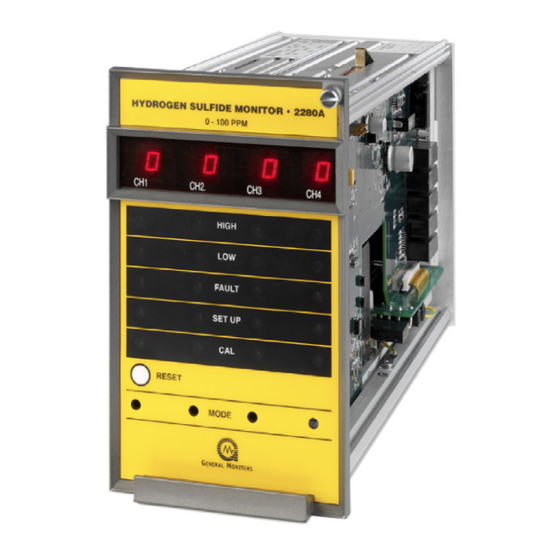
Page 10: Controller
Model 2280A Figure 1: Model 2280A Controller The Model 2280A is a four-channel system where the controller continuously monitors the inputs of four sensors. The sensors are monitored independently (i.e. they are not scanned, nor are the signals summed). Each channel has the following: •... -
Page 11: Sensor Assembly
Model 2280A NOTE: A service-loop is necessary between the Model 2280A Controller’s rear panel terminals and field/power wiring. This service loop permits the controller to be removed or slid forward for servicing. This service loop is a definite advantage when replacing or changing a controller. Sensor Assembly Four sensor assemblies are normally supplied with the system. -
Page 12: Installation
Model 2280A 2.0 Installation Location of the Controller The Model 2280A controller should be installed in a weather-protected, non- hazardous area. The following hardware is available to assist installation: Part Description Part Number 98 mm (4”) panel mount frame 10199-1 483 mm (19”) rack mount frame 10200-1 98 mm (4”) blank panel... -
Page 13: Battery Backup
The battery rating (ampere-hour capacity) is dictated by the length of time power outages may last. A Model 2280A Controller requires approximately 2 ampere (peak) at 24 VDC. General Monitors recommends that a Lead-Acid type battery be used. This type of battery can be expected to last for several years with minimum maintenance. -
Page 14: Analog Output Connection
Model 2280A Analog Output Connection CAUTION: The Analog Output must either be used or jumpered. If not, the Model 2280A indicates a fault in the normal mode with the display reading “A0” and the Fault LED flashing. The two analog output terminals, AO (+) and AO (-), are located at the rear of the unit. -
Page 15: Sensor Installation
The presence of such materials in an area does not preclude the use of a sensor. The feasibility of using a sensor in such areas must be determined by an analysis of the specific factors in each application. Consult General Monitors before attempting any such installation. -
Page 16: Table 2: Sensor Wire Colors
3. Connect the cable so that the terminal color at the sensor housing matches the terminal color at the controller. General Monitors’ sensor leads are color coded, and should be connected to the rear Terminal Connector as shown in... -
Page 17: Table 4: Cable Length
Model 2280A The maximum cable length, using four conductor cable, should be such that the total loop resistance of any signal path (for example the black leads) does not exceed 20- Ohms at 25º Celsius. The following table may be used as a guide to determine cable length versus wire size: Feet Meters... -
Page 18: Figure 3: Junction Box Assembly Sensor
Model 2280A Figure 3: Junction Box Assembly Sensor... -
Page 19: Alarm Wiring Connections
Model 2280A Alarm Wiring Connections The Model 2280A can be configured to have individual alarm and fault relays for each channel, or have a common set of relays (that is, any alarm of fault occurring on any of the four channels will cause a relay on the channel one card to activate). The alarm relays may be operated as normally de-energized or normally energized, and latching or non-latching. -
Page 20: Multiple Controller Operation
Model 2280A CAUTION: Inductive loads, such as bells, buzzers, relays, contactors, solenoid valves, etc., connected to the high alarm, low alarm and fault alarm relays must be clamped down as shown in the diagrams below. Unclamped inductive loads can generate voltage spikes in excess of 1000 Volts. -
Page 21: Figure 5: Common Relay & Rear Terminal Connections
Model 2280A Figure 5: Common Relay & Rear Terminal Connections... -
Page 22: Figure 6: Discrete Relay & Rear Terminal Connections
Model 2280A Figure 6: Discrete Relay & Rear Terminal Connections... -
Page 23: Start Up And Operation
Model 2280A 3.0 Start Up and Operation 3.1 Types of User Interfaces User interfaces are provided so that the operator may interpret and direct the Model 2280A in the performance of its various functions. User interfaces consist of a digital display, status indicators, a mode button, and a reset button. -
Page 24: Initial Application Of Power
Model 2280A 3.2 Initial Application of Power Before applying power for the first time, double-check all the wiring components. Insure that the sensor is correctly installed. The system has a time delay feature. The High and Low alarm circuits are disabled for approximately 45 seconds after power is applied. -
Page 25: Calibration Preparation Instructions
3.5.1 Gas Application Options 3.5.1.1 Breaker Bottles and Ampoules General Monitors offers ampoules with breaker bottles as a method of reliably introducing calibration gas to the Model 2280A. The ampoule is placed inside the breaker bottle into the breaker slot, and the breaker bottle is placed over the sensor. The ampoule should contain 50% full-scale of H S of the sensor range. -
Page 26: Figure 8: Portable Purge Calibrator
Model 2280A system for field calibration of H S sensors. The bottle is filled with a hydrogen sulfide S) in air mixture and is available in 7 concentrations. The temperature limitation for operation and storage is 0°F to +130°F (-18°C to +54°C). Make sure the Model 2280A has had power applied for at least 24 hours to ensure that the metal oxide film of the sensor has stabilized. -
Page 27: Calibration Check Mode
Model 2280A 3.6 Calibration Check Mode This procedure is used to periodically check the response of an installed system to a known concentration of H S gas that is at least 50% of the full-scale reading. To perform a calibration check, use the following procedure: NOTE: The Calibration Check mode cannot be entered if the channel is in alarm. -
Page 28: Aborting Calibration
Model 2280A 2. Enter Calibration mode by following the procedure for entering Calibration Check mode in 3.6. Continue to press and hold the Mode button until the CAL LED becomes steady, approximately fifteen seconds. When the CAL LED is steady, release the Mode button. -
Page 29: Entering The Password
Model 2280A without the operator pressing the Mode button, the setup routine accepts that selection and moves on to the next option available. NOTE: Before entering the Setup mode to make changes, the user should fill out the Setup Mode Selection Table (Section 3.9). This aids the user during the selection process in the Setup mode. -
Page 30: Low Alarm Options
Model 2280A The HIGH LED on the front panel flashes while the latching/non-latching option displays. The display indicates the current selection, (nL or LA). Press the Mode button to toggle the selection. Latching (LA) is the factory default for this selection. The last High alarm option to appear on the display is the alarm set point (trip level). -
Page 31: Led Test
Model 2280A If password disabled is selected, the unit returns to normal operation. If this setting is changed from password disabled to password enabled, the user enters a new password. The unit displays the left digit of the existing password (flashing on the display). The right digit is blank until the left digit has been selected. -
Page 32: Check Points For Calibration And Operation
Model 2280A 3.10 Check Points for Calibration and Operation 3.10.1 Frequency of Calibration GMI recommends that the calibration be checked on each sensor at least every ninety (90) days. If a sensor is installed where it may be subjected to splashing water, mud or dirt accumulation, or adverse gases, more frequent calibration is recommended. -
Page 33: Maintenance
General Maintenance Once installed, the Model 2280A Controller requires little or no routine maintenance, other than periodic calibration checks. General Monitors recommends that a calibration schedule be established and adhered to. GMI also recommends that a logbook be kept, showing calibration dates and dates of sensor replacement. -
Page 34: Troubleshooting
If equipment or qualified personnel required for various tests is not available, it is recommended that the defective unit be returned to General Monitors for repair. A complete written description of the problem should be included. -
Page 35: Fault Codes
Model 2280A 5.3 Fault Codes In addition to the Fault LED on the front panel, the Model 2280A provides a fault code on the digital display whenever a fault condition occurs. The Fault Codes that can appear on the digital display are: FAULT DESCRIPTION SOLUTION... -
Page 36: Customer Support
United Arab Emirates 6.2 Other Sources of Help General Monitors provides extensive documentation, white papers and product literature for its complete selection of safety products. A selection of these documents are available online at the General Monitors website at http://www.generalmonitors.com. -
Page 37: Appendix
7.0 Appendix Warranty General Monitors warrants the Model 2280A to be free from defects in workmanship or material under normal use and service within two years from the date of shipment. General Monitors will repair or replace without charge any such equipment found to be defective during the warranty period. - Page 38 Model 2280A current output signal tracks the digital reading as well. The adsorption process is reversible so that when the air containing no H S diffuses into the sensor, the H S gas desorbs. The semiconductor then resumes its original “clean air” resistance value.
-
Page 39: General Specifications - Controller
Model 2280A 7.3 General Specifications - Controller 7.3.1 Mechanical Specifications Dimensions: 4.0”W x 6.9”H x 11.5”D (102mm x 175mm x 292mm) Weight: 6.2 lbs. (2.86 kg) Mounting: Rack, panel, wall 7.3.2 Environmental Specifications Temperature Range: 32°F to 140°F (0°C to 60°C) Storage Temperature: -4°F to +149°F (-20°C to 65°C) Operating Humidity:... -
Page 40: Recommended Spare Parts List
Model 2280A 7.4.3 Recommended Spare Parts List Description Part Number Fuse, .8 amp, 250 VAC 951-012 Fuse, 3.15 amp, 250 VAC 951-213 Sensor Per Original Order Table 10: Spare Parts List... -
Page 41: Sample Calibration Schedule And Checklist
Model 2280A Sample Calibration Schedule and Checklist Sensor Serial Number Location ___________________ _____________________ 1. Installation and Preliminary calibration. Date: __________________ Record date after preliminary calibration is done. Date: __________________ 2. 24-hour calibration. Record date after 24- hour calibration is done. 3. -
Page 42: Product Configuration Table
Model 2280A Product Configuration Table MODEL 2280A FOUR CHANNEL H2S CONTROLLER A. CONTROLLER 2280A Model 2280A Controller 6.2 lbs. 1 (Std) -P1 110 VAC/24VDC 220 VAC/24 VDC B. RELAY ALARM (STD) COMMON RELAY/COMMON ALARMS DISCRETE RELAYS/DISCRETE ALARMS RELAY – STATE - NC (STD) RS 1NC LATCH ALARM, NON-LATCH WARN, DE-ENERGIZED... - Page 43 Model 2280A D. H2S METER SCALE: (STD) H2S1 99 PPM SCALE H2S2 50 PPM SCALE H2S3 20 PPM SCALE E. ACTIVE CHANNELS: Controller Only One Active Channel 6.2 Lbs. Cal Kit Refill 4 Ea #20/#50/#1 0.7 Lbs. H2S sensor simulator w/o SW 0.5 Lbs.
-
Page 44: Panel Assembly, Panel Mount - 98, Ref: 10199C
Model 2280A 7.6.1 Panel Assembly, Panel Mount – 98, Ref: 10199C Figure 9: Panel Assembly, Panel Mount – 98, Ref: 10199C... -
Page 45: Interconnection Drawing Zone Control Model 2280A Controller
Model 2280A 7.6.2 Interconnection Drawing Zone Control Model 2280A Controller Figure 10: Interconnection Drawing Zone Control Model 2280A Controller... - Page 46 ADDENDUM Product Disposal Considerations This product may contain hazardous and/or toxic substances. EU Member states shall dispose according to WEEE regulations. For further General Monitors’ product WEEE disposal information please visit: www.generalmonitors.com/customer_support/faq_general.html All other countries or states: please dispose of in accordance with existing federal, state and local...
- Page 47 Model 2280A Index alarm relays, 13 Mounting, 6 ampoules, 19 password enabled/disabled option, 23 analog output, 18 Periodic Calibration Checks, 27 auto-calibration, 3 polycarbonate inlay, 3 battery backup, 7 portable purge calibrator, 19 breaker bottles, 19 recommended spare parts list, 34 cable length, 11 replacing a sensor, 26 calibration check, 21...
Need help?
Do you have a question about the MAN2280A and is the answer not in the manual?
Questions and answers