Table of Contents
Advertisement
Quick Links
Advertisement
Table of Contents

Summary of Contents for Arfa 1018S
- Page 1 METAL CUTTING BAND SAW 1018S / 1018SV INSTRUCTION MANUAL 1018S/SV-061117-R1...
- Page 2 WARNING Some dust created by power sanding, sawing, grinding, drilling, and other construction activities contains chemicals known to the State of California to cause cancer, birth defects or other reprodrctive harm. Some examples of these chemical are: ‧Lead from lead-based paints. ‧Crystalline silica from bricks, cement and other masonry products.
-
Page 3: Table Of Contents
Table Of Contents Page No Overall Aspect……………………………………………………………….………..2 1 Warning ….………………………………………………………………….….….. 3 2 Specification …………………….……………………………………………… .. 6 3 Transportation of machine …………………………………………………..….. 6 4 Minimum Room Space For Machine Operation ………………………………... 8 5 Make proper tooth selection ……………………………………….………….…. 8 6 BI-Metal speeds and feeds .…………………….……………………………….. 9 7 Connecting saw to power source ……………………………………………….. -
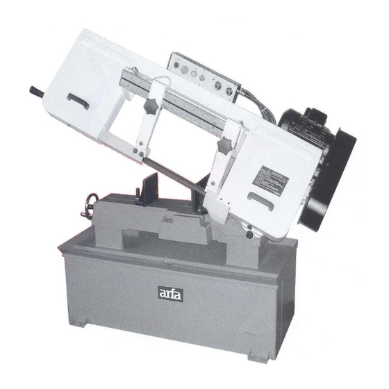
Page 4: Overall Aspect
Overall Aspect CAUTION Install saw blade and blade guard before use. Set proper blade tension to prevent any danger caused by damaged saw blade or work piece. -
Page 5: Warning
1 WARNING: FAILURE TO FOLLOW THESE RULES MAY RESULT IN SERIOUS PERSONAL INJURY As with all machinery there are certain hazards involved with operation and use of the machine. Using the machine with respect and caution will considerably lessen the possibility of personal injury. - Page 6 job better and be safer at the rate for in vise before starting cut. which it was designed. (15). GROUNDALL TOOLS. If tool is (3). USE RIGHT TOOL. Don’t force tool equipped with three-prong plug, it should or attachment to do a job for which it was be plugged into a three-hole electrical not designed.
- Page 7 check for alignment of moving parts, surfaces when a soluble on is used as binding of moving parts, breakage of coolant, pay particular attention to wiping parts, mounting, and any other conditions dry the surfaces where fluid accumulates that may affect its operation. A guard or and does not evaporate quickly, such as other part that is damaged should be between the machine bed and vise.
-
Page 8: Specification
2 SPECIFICATION MOTOR 2HP,,( 1Φ, 3Φ) 35-60-88-115 MPM 60Hz (114-196-288-377 FPM) Saw Blade Speed (for S model) 29-50-73-96 MPM 50Hz (95-164-239-314 FPM) 35~115 MPM 60Hz (114~377 FPM) Saw Blade Speed (for SV model) 29~96 MPM 50Hz (95~314 FPM) Blade Size(mm) 27 x 0.9 x 3090 Dimension L x W x H (mm) 1720x620x1055... - Page 9 Installation: As this machine weights 310 kg. It is recommended that the machine shall be transported, with help of lifting jack. Transportation Recommendation: (1). Tighten all locks before operation. (2). ALWAYS Keep proper footing & balance while moving this 310kgs machine, and only use heavy duty fiber belt to lift the machine as Fig.
-
Page 10: Minimum Room Space For Machine Operation
4 MINIMUM ROOM SPACE FOR MACHINE OPERATION 5 MAKE PROPER TOOTH SELECTION For maximum cutting efficiency and lowest cost per cut, it is important to select the blade with the right number of teeth per inch (TPI) for the material being cut. The material size and shape dictate tooth selection. -
Page 11: Bi-Metal Speeds And Feeds
1.The shape of the workpiece. Squares, Rectangles, Flats (Symbol : ■) Locate the width of cut on the chart. (Inches on the outer circle and millimeters on the inner circle.) Select the tooth pitch on the ring marked with the square shape which aligns with the width of cut. - Page 12 MATERIAL ALLOY BAND SPEED ASTM NO. FT./MIN M/MIN Copper 173,932 Alloy 330,365 623,624 230,260,272 280,264,632,655 101,102,110,122,172 1751,182,220,510 625,706,715,934 Carbon 1117 Steel 1137 1141,1144 1141 HI STRESS 1030 1008,1015,1020,1025 1035 1018,1021,1022 1026,1513 A36(SHAPES),1040 1042,1541 1044,1045 1060 1095 Ni-Cr-Mo 8615,8620,8622 Alloy Steel 4340,E4340,8630 8640 E9310...
-
Page 13: Connecting Saw To Power Source
Stainless Steel 410,502 440C 304,324 304L 316,316L TELLTALE CHIPS Chips are the best indicator of correct feed force. Monitor chip information and adjust feed accordingly. Thin or powdered chips – increase feed rate or reduce band speed. Burned heavy chips – reduce feed rate and/or band speed. -
Page 14: Starting And Stopping Machine
8 STARTING AND STOPPING MACHINE Raise the saw frame to the up position. The machine is started by pushing the start button (C) Fig. 2. And it will continue to run until the saw arm is in the down position at the end of the cut, or when the stop button (D) is pushed. -
Page 15: Changing Speeds And Adjusting Belt Tension
10-1 CHANGING SPEEDS AND ADJUSTING BELT TENSION ( For 1018S) Your machine is provided with a range of four speeds: 35,60, 88 and 115 MPM feet per minute. To change speeds, pro-ceed as follows: 1. Disconnect the machine from the power source. -
Page 16: Adjusting Blade Tension
11 ADJUSTING BLADE TENSION To tension the blade, lift up the left wheel cover and turn the blade tension handle (A) Fig. 8, clockwise. A pointer and tension scale (B) is located underneath the wheel. The scale is graduated to indicate blade tension of 20,000, 30,000 and 35,000 pounds per square inch (psi). -
Page 17: Adjusting Cutting Pressure Of Saw Arm
14 ADJUSTING CUTTING PRESSURE OF SAW ARM The cutting pressure of the saw arm has been set at the factory and should not need further adjustment. If adjustment should ever become necessary, lower the saw arm to the horizontal position. Loosen locknut (A) Fig.11. until the Fig. -
Page 18: Coolant
the way to the right, and lock spring loaded clamp handle (D). 2. Using a combination square (E), place one end of the square against the vise jaw and the other end against the blade as shown in Fig. 13. Check to see if the vise jaw is 90 degrees to the blade. -
Page 19: Adjusting Stock Advance Stop
The rate of coolant flow is controlled by the stop valve lever (B) Fig. 16 which directs the coolant onto the blade at (C). The lever (B) is shown in the off position. 17 ADJUSTING STOCK ADVANCE STOP The stock advance stop is used mainly when more than one piece of work is to be cut to the same length. -
Page 20: Setting Up The Machine For Operation
19 SETTING UP THE MACHINE FOR OPERATION Fig. 20 1. Select the proper speed and blade for the type of material you are cutting. 2. Make sure the blade tension is adjusted properly. 3. Raise the saw frame and close the feed ion/off knob (E) Fig. 20. 4. -
Page 21: Removing And Installing The Blade
20 REMOVING AND INSTALLING THE BLADE Fig. 21 When it becomes necessary to replace the blade. Proceed as follows: 1. Disconnect the machine from the power source. 2. Raise the saw frame about 6” and close the feed on ioff knob (E) Fig 21, by turning it clockwise as far as it will go.”... -
Page 22: Gear Box
21 GEAR BOX The gear box should be drained and refilled after the first 50 hours of use and thereafter every 5 months, with mobil synthetic gear oil, SHC-636, ISO viscosity grade 680. this oil meets or exceeds american gear manufacturers association (A.G.M.A.) #8 compounded cylinder oil specifications. -
Page 23: Trouble Shooting
22 TROUBLE SHOOTING Symptom Possible Cause(s) Corrective Action Machine can not be Power is not plugged; the Check motor started power light on control panel is specification; connect the not on. power with correct power Motor can not be started; supply. - Page 24 6.Blade twist 6. Replace with a new blade, and adjust blade tension 7. Insufficient blade 7. Tighten blade tension adjustable knob 8. Blade slide 8. Tighten blade tension Unusual Wear on Blade guides worn. Replace. Side/Back of Blade Blade guide bearings not Adjust as per operators adjust properly manual...
- Page 25 7. Blade guide assembly loose 8. Re-track blade according 8. Blade truck too far away from to operating instructions. wheel flanges Bad Cuts (Rough) 1. Too much speed or feed 1. Decrease speed or feed. 2. Blade is too coarse 2.
-
Page 26: Circuit Diagram
23 Circuit Diagram 270V(W/Cyinder) SCHEDULE OF ELECTRICAL EQUIPMENT Parts umber ltem Designation and function ET1324 Transformer ET1127 Relay ET1231 Push-Button Switch ET1615 Limit Switch ET1417 Light ET1811 Fuse ET1157 Contactor ET2019 Overload ET1245 Emergency Stop ET1235 Pump Switch... -
Page 27: Parts Drawing
-25-... - Page 28 -26-...
-
Page 29: Parts Lists
PARTS LIST MODEL NO. 1018S CODE NO PART NO DESCRIPTION SPECIFICATION QTY NOTE ET1924S Control Box MB240FS 1/8HP 115/230V Pump Set 181256 Coolant Tank HD809 1/2"-350mm Hose HD659 PT1/2x1/4 Coupler MB13102 1/8HP 115/230V Pump W004 1/4"x19xt1.5mm Washer S717 1/4"-20*5/8"L Cross Round Head Screw... - Page 30 PARTS LIST MODEL NO. 1018S CODE NO PART NO DESCRIPTION SPECIFICATION QTY NOTE HS061 M10-1.5Px35L Hex. Head Screw 189002G Base HE501 M5-0.8Px8L Cross Tablet Head Screw 187064 Degree-Meter HS430 M8-1.25Px10L Hex. Headless Screw HN005 M8-1.25P Hex. Nut HS051 M8-1.25Px45L Hex. Head Screw...
- Page 31 PARTS LIST MODEL NO. 1018S CODE NO PART NO DESCRIPTION SPECIFICATION QTY NOTE HS243 M8-1.25Px25L Hex. Head Screw HI105 ø8.2-2.5t Spring Washer HW005 ø8.4*ø17Xt1.6mm Washer 1965015-1 Blade Adjustable Knob HW023 ø10.5*ø21Xt2mm Washer 189077 209-1 Label 187020 Arm(Left) 1965014 C100 ∮8...
- Page 32 PARTS LIST MODEL NO. 1018S CODE NO PART NO DESCRIPTION SPECIFICATION QTY NOTE 189074 Bracket 189072 HS558 M5-0.8P*8L Cross Round Head Screw HW003 ø5.3*ø10Xt1mm Washer HS558 M5-0.8P*8L Cross Round Head Screw 189073 Bracket HS241 M8-1.25Px15L Hex. Head Screw 1965052 Knob 103127 M6-1.0Px10L...
- Page 33 PARTS LIST MODEL NO. 1018S CODE NO PART NO DESCRIPTION SPECIFICATION QTY NOTE 1965027 25.4*0.9*3090*5/8Tmm Blade 196304 Drive Wheel HS258 M10-1.5Px20L Hex. Head Screw HW106 ∮10.2-3t Spring Washer 19116S-1 1:30 8mm Gear Box Assembly 19116S-3 1:30 8mm Gear Box Assembly...
- Page 34 PARTS LIST MODEL NO. 1018S CODE NO PART NO DESCRIPTION SPECIFICATION QTY NOTE 103127-3 1/2"x143cm 354-9 Net Tube HD809 1/2"x32cm 354-10 Net Tube 198086J Knob 355-1 198051AJ Blade Tension Handle CA51203 51203 Bearing 189053 Tension Indication Ring 198093 ∮ID16.3X∮31.5X1.8t Spring Washer...
- Page 35 PARTS LIST MODEL NO. 1018S CODE NO PART NO DESCRIPTION SPECIFICATION QTY NOTE 181138B Acme Nut W002 1/2"*28*t2 Washer -33-...
- Page 36 MANUFACTURER: ADDRESS: SERIAL No.: PLEASE WRITE DOWN THE SERIAL NO. ON THIS BLOCK FROM THE NAME PLATE AFTER YOU RECEIVE THIS MACHINE.
Need help?
Do you have a question about the 1018S and is the answer not in the manual?
Questions and answers