
Summary of Contents for Blankom A-QAMOS-IPM
- Page 1 ...setting signals Device MANUAL A-QAMOS-IPM IP-/ ASI-TV Modulator / Multiplexer IP / SFP / ASI → MUX → DVB-C (16xQAM) Part no. 5111.81 5111.83...
-
Page 2: Table Of Contents
1. Savety and operating instructions ........................4 2. Device variants ...............................4 3. Software options ............................4 4. General ................................4 5. Functional description ............................4 6. Explanation of the operating elements ......................5 6.1 Front view ..............................5 6.2 Meaning of the status LED‘s .........................5 6.3 Rear view ..............................5 6.4 Meaning of the LED‘s at the rear .........................6... - Page 3 Contents 9.4 Fault prevention ............................32 9.5 Glossary - parameter declaration [min. … max. range] ................32 10. Block diagram .............................33 11. Application example ...........................33 12. Technical data ............................34 13. Glossary ..............................35 14. Bibliography ..............................35 15. Notes on the device software ........................36 16.
-
Page 4: Savety And Operating Instructions
/ SD-Card 4. General The IP-/ ASI-TV Modulator/ Multiplexer A-QAMOS-IPM is a devices of the head end system A-LINE, which is conceived as a complete system for big and middle sized networks. The A-QAMOS-IPM converts transponders included in IP or ASI transport streams into QAM signals to transmit them in cable networks assemble them in an integrated multiplexer. -
Page 5: Explanation Of The Operating Elements
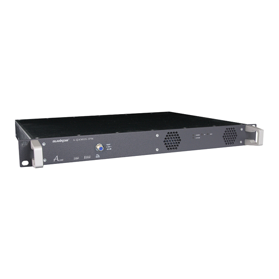
6. Explanation of the operating elements 6.1 Front view Amplifier Status LED "POWER" Status LED "MUX" (Multiplexer) Status LED "SYSTEM" Status LED "RF" (RF output) 6.2 Meaning of the status LEDs Desingation Color Status Meaning of the LEDs green constant device is ready POWER amber... -
Page 6: Meaning Of The Leds At The Rear
6.4 Meaning of the LEDs at the rear 6.4.1 LED‘s at the 10 / 100 / 1000 Mbit stream port 1 Designation, Color Status Meaning of the display only illuminated when the cable connection is a GbE connection (does constant GbE connect LED, not light up at a 10/ 100 Mbit connection) green... -
Page 7: Settings By Web Interface
7. Settings by web interface To use all functions of the device activate Java Script in your browser settings. Settings via checkbox are applied immediatelly, but not stored in memory! So they would be lost on a possible restart of the device. To save these settings the “send“ button must be pressed. Please send and store your settings by pressing the“send“... -
Page 8: Setting Of Individual Parameters
7.2 Setting of individual parameters Here you can set certain parameters of the device or perform configurations. The various setting menus can be selected in the navigation tree on the left side. The setting is supported by an online help. If you mouse over a parameter explanations of this parameter are displayed in an orange colored text box in the lower part of the screen. -
Page 9: Menüpunkt „Überblick
7.2.1 Menu "Overview" This page provides an overview of the 16 channels. The display is separated for the multiplexer and QAM output. If a channel works without errors, "MUX" resp. "QAM" is displayed in a green color. If the power is turned off "QAM:off" is displayed behind the respective channel. -
Page 10: Menu "Ip Input
7.2.2 Menu “IP input” This is the menu for the network configuration of the IP input and the configuration of the 62 stream ports. They compile the 16 desired transponders for transmission. In the top field the configuration options for the two stream ports are displayed. Stream Port 2 is only available after enabling the software option (»chapter 7.2.8). -
Page 11: Sfp Option
7.2.2.1 SFP option The SFP option allows the connection of different devices to the IP input. Depending on the SFP device various management and media types can be connected to the A-PALIOS-IPM4. So the IP input can be expanded by another IP data source. -
Page 12: Menu "Multiplexer
7.2.3 Menu ”Multiplexer” In this menu for the compilation of the channel packages, that are transferred to the output channels. On the left the 64 IP inputs (62 IP channels + ASI channel + media player), on the right the 16 outputs are displayed. To make alterations, click the prefered output channel (active channels are highlighted in orange color). - Page 13 Further you can select, with which priority (low, middle or high) the transfer of services is done. Due to the dynamic transmission rate of the services the brutto bitrate of the channel could be exceeded. This could lead to malfunctions up to total failure of services.
-
Page 14: Menu "Transponders
7.2.4 Menu ”Transponders” In this menu the transponder and program selection is done. The user interface is divided in two tables. left table In the the current transponder allocation of the 16 output channels are displayed. The selection of the output channel is done within the chosen frequency raster (“Setup →... -
Page 15: Menu "Settings
7.2.5 Menu ”Settings” Each channel can be adjusted individually according to individual requirements. The channel can be selected by clicking either left in the navigation tree or by clicking one of the tabs above the set-up tables. The following parameters are adjustable: Input Channel name of transponder compiled in... - Page 16 Transport stream processing SDT processing on, off Original network ID setting range: 0...65535 Original transport stream ID setting range: 0...65535 NIT processing on, off Network name freely selectable (max. 30 characters) Network ID setting range: 0...65535 CAT processing on, on with CA filter, off CA system ID Setting range: 0...65535 Operator ID...
-
Page 17: Menu "Language
7.2.7 Menu ”Service” Here you find all service information: BLANKOM service hotline and e-mail address, the manual as pdf file and a link to the BLANKOM homepage where the latest software release is available. Also the currently installed software release is displayed. -
Page 18: Menu "Setup
7.2.8 Menu ”Setup” In this menu, various administrative and system settings are made. The following can be configured: Graphical User Interface: GUI settings › Help info within the status line of the browser By default, the online help is displayed in an orange colored text box at the bottom of the page. - Page 19 › Optimization for low-speed data connectivity Selecting this option reduces the image size to accodate a low-speed data connection (GSM). › Output frequency raster With this selection box you can set the output channel spacing, which is pre-set for adjustment of the QAM channels.
- Page 20 System administration By default the short list is displayed (see first picture). Backup The default is to save or load the complete configuration. If under “GUI setup→Display all system files“ is selected, all system files are listed. The system files can also be loaded or saved separately (see figure below).
- Page 21 Settings of the web interface The device supports the DHCP functionality. DHCP-Client is factory default. Note, that after each factory reset the device is set to “DHCP-Client“. If the DHCP functionality is set to “Off“, the appropriate fields for IP number, subnet mask and gateway can be set manually to fit the network.
- Page 22 SNMP-Option First section: The “Mode“ selection field enables or disables the SNMP functionality, including the sending of traps. The selector “Version“ sets the SNMP version (version 1, 2 or 3). In the two fields below, the reading and writing via SNMP is separately indicated for the versions 1 and 2.
- Page 23 (»chapter 7.2.3). To produce a transport stream file in the appropriate format, the company BLANKOM provides a corresponding conversion tool. This may generate a corresponding file in the transport stream format, which the device can handle. A detailed description of the conversion tool can be found in »chapter 9.
-
Page 24: Menu "Level
7.2.9 Menu ”Level” In the first section you can enable or disable the loop through output. If enabled, select the nominal level for all 16 channels in the range from 60 ... 78 dBµV. If the loop is disabled, the output level of the 8 channels can be set in the range of 72 ... -
Page 25: Menu "Amplifier
When listing the output parameters for each channel the available brutto bit rate, the used channel bit rate and the possibly existing overflow bit rate are displayed. The used channel bit rate should be smaller than the brutto bit rate. Otherwise it can cause disturbances or even failure of the transferred services. -
Page 26: Menu "Nit
7.2.12 Menu ”NIT” The NIT processing for all to a headend associated devices of the A-QAMOS and QAMOS product group can be done in 2 ways: as an automatic or manual NIT processing. The simplest and by installation and support expense safest way is the automatic NIT processing. The precondition is that all to the headend associated above mentioned devices have a different IP address and an Ethernet switch must be connected to each other. -
Page 27: Manual Nit Processing
of the headend. Here the NIT transmission per channel can be switched on or off easily and the network name and network ID can be changed. The settings are identical to the menu Settings→Transport stream processing (»chapter 7.2.5). Confirm and store with the “Send“ button. 7.2.12.2 Manual NIT processing After the preparation or initializing of the NIT, described in 7.2.11, first it must be called the edit mode of the NIT in... -
Page 28: Menu "Lcn
7.2.14 Menu ”Program table” The program table gives an overview of the channel allocation of the A-QAMOS-IPM. The overview begins with the output frequency and output channel identifier for each transmission channel. Under them all TV and radio programs are listed, which are transmitted in this channel. -
Page 29: Factory Settings
8. Factory settings A short pressing of the reset button on the front of the device causes a reboot, i.e. the device restarts and all stored values are restored. If the device must be reset to factory settings, please press the reset button until the “POWER“ and “SYSTEM“... -
Page 30: Conversion Tool To Create A Compliant Ts File
The option "Media player" gives an opportunity to install a TS file from a via network connected PC to the device. The file must have a DVB standard conform format. BLANKOM affords a conversion program which generates a compliant file from a large number of video file formats. Following this, the converted file can be fed-in as an additional channel. -
Page 31: Installation And Integration Of The Conversion Tool
When you install the software (Java, VLC player) read the message windows to refuse activities of third-party programs or other advertising. For the following software releases, the functionality of the video converter tool has been successfully tested: system software Windows XP und Windows7 Java with version 6 and higher FFmpeg... -
Page 32: Fault Prevention
This switch enables the compression of null packets in the transport stream. Thus, a significant reduction in file size is achieved especially for files that have a big difference between video and transport stream bit rate. However, the resulting files are not compatible with conventional software programs.These compressed files are used only by the A-QAMOS-IPM or compatible devices of BLANKOM company. -
Page 33: Block Diagram
ASI-TS IN ASI-TS IN IP-TS IN 2 IP-TS IN 2 IP-TS IN 2 IP-TS IN 2 CONTROL IP-TS IN 1 CONTROL IP-TS IN 1 CONTROL IP-TS IN 1 CONTROL IP-TS IN 1 192.168.1.100 192.168.1.101 192.168.1.102 192.168.1.103 A-QAMOS-IPM A-QAMOS-IPM A-QAMOS-IPM A-QAMOS-IPM... -
Page 34: Technical Data
12. Technical data Signal quality MER ≥ 45 dB Shoulder attenuation ≥ 53 dB IP input (stream port) Spurious 45...862 MHz ≥ 60 dB Network connection (LAN/ WAN) max. frequency stability 30 kHz Ethernet,10/ 100/ 1000 Base-T Output level stability ±... -
Page 35: Glossary
13. Glossary Address Resolution Protocol Network Interface Module Asynchronous Serial Interface Nios product name for a processor Bandwidth Network Information Table Digital Video Broadcasting Program Clock Reference (-C Cable, -S Satellite, -S2 Satellite 2, -T Terrestrial) Program Service Information ETSI European Telecommunications Standards Quadrature Amplitude Modulation Institute... -
Page 36: Notes On The Device Software
15. Notes on the device software Device Software of the A-QAMOS-IPM © BLANKOM Antennentechnik GmbH Bad Blankenburg Copyright This device software based on top of Linux 3.6.8 is free software: you can redistribute it and/ or modify it under the terms of the GNU General Public License as published by the Free Software Foundation, either version 2 of the License, or (at your option) any later version. -
Page 37: Declaration Of Conformity
Declaration of Conformity Manufacturer: BLANKOM Antennentechnik GmbH Hermann – Petersilge – Straße 1 07422 Bad Blankenburg Germany Product Name: IP- / ASI-TV Modulator / Multiplexer Type Name: A-QAMOS-IPM Type N 5111.81, 5111.83 BLANKOM Antennentechnik GmbH confirms that the mentioned products meet the guideline(s) of the Council for the approximation of legislation of the member states.
Need help?
Do you have a question about the A-QAMOS-IPM and is the answer not in the manual?
Questions and answers