Table of Contents
Advertisement
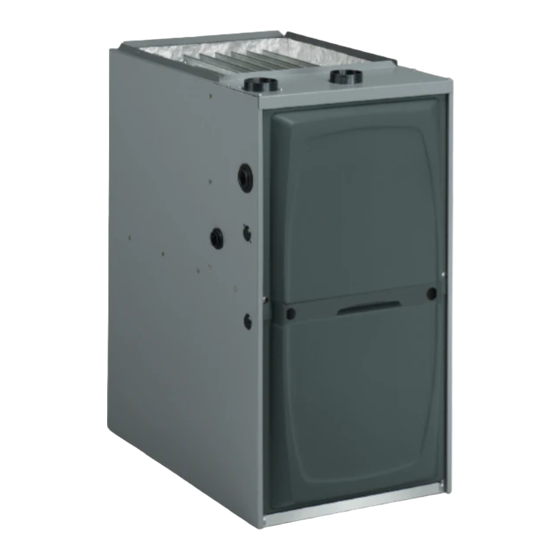
Warm Air Gas Furnace / Downflow Air Discharge
This is a safety alert symbol and should never be ignored. When you see this symbol on labels or in
manuals, be alert to the potential for personal injury or death.
As with any mechanical equipment, personal injury can
result from contact with sharp sheet metal edges. Be
careful when you handle this equipment.
Unit Dimensions ................................................................ 2
Parts Arrangement............................................................. 3
Gas Furnace ...................................................................... 4
Shipping and Packing List ................................................. 4
Safety Information ............................................................. 4
Use of Furnace as Construction Heater ............................ 5
General .............................................................................. 6
Combustion, Dilution & Ventilation Air ............................... 6
Setting Equipment ............................................................. 9
Filters ............................................................................... 12
Duct System .................................................................... 12
Pipe & Fittings Specifications .......................................... 12
Joint Cementing Procedure ............................................. 14
Venting Practices ............................................................. 14
*P507405-05*
(P) 507405-05
507405-05
INSTALLATION INSTRUCTIONS
A96DS2V
Direct Vent & Non-Direct Vent
This manual must be left with the homeowner for future reference.
CAUTION
TABLE OF CONTENTS
Improper installation, adjustment, alteration, service
or maintenance can cause property damage, personal
injury or loss of life. Installation and service must
be performed by a licensed professional installer (or
equivalent), service agency or the gas supplier.
Vent Piping Guidelines .................................................... 15
Gas Piping ....................................................................... 34
Electrical .......................................................................... 36
Unit Start-Up .................................................................... 52
Gas Pressure Adjustment ................................................ 53
High Altitude Information ................................................. 54
Other Unit Adjustments.................................................... 55
Blower Motor Performance .............................................. 56
Integrated Control Diagnostic Modes .............................. 60
Service............................................................................. 67
Planned Service .............................................................. 69
Start-Up & Performance Check List ................................ 70
A Lennox International, Inc. Company
Issue 1621
WARNING
Manufactured By
Allied Air Enterprises LLC
215 Metropolitan Drive
West Columbia, SC 29170
Page 1 of 72
Advertisement
Table of Contents

Related Manuals for Armstrong Air Conditioning A96DS2V

Summary of Contents for Armstrong Air Conditioning A96DS2V
-
Page 1: Table Of Contents
INSTALLATION INSTRUCTIONS A96DS2V Warm Air Gas Furnace / Downflow Air Discharge Direct Vent & Non-Direct Vent This manual must be left with the homeowner for future reference. This is a safety alert symbol and should never be ignored. When you see this symbol on labels or in manuals, be alert to the potential for personal injury or death. -
Page 2: Unit Dimensions
Unit Dimensions - inches (mm) Model Number A96DF2V 045-12 17-1/2 16-3/8 070-16 090-20 19-7/8 19-1/2 110-20 Page 2 of 72 Issue 1621 507405-05... -
Page 3: Parts Arrangement
Expanded View Figure 1 507405-05 Issue 1621 Page 3 of 72... -
Page 4: Gas Furnace
Gas Furnace Shipping and Packing List This Category IV gas furnace is shipped ready for installation Package 1 of 1 contains: in the downflow position. 1 - Assembled Gas Unit 1 - Bag assembly containing the following: The furnace is equipped for installation in natural gas 1 - Snap bushing applications. -
Page 5: Use Of Furnace As Construction Heater
In Canada, installation must conform with current National Standard of Canada CSA-B149 Natural Gas and Propane Installation Codes, local plumbing or waste water codes and other applicable local codes. In order to ensure proper unit operation in non-direct vent applications, combustion and ventilation air supply must be provided according to the current National Fuel Gas Code or CSA-B149 standard. -
Page 6: General
• Air filters must be replaced upon construction completion. • The input rate and temperature rise must be set per the WARNING furnace rating plate. • One hundred percent (100%) outdoor air must be provided The State of California has determined that this product for combustion air requirements during construction. - Page 7 air is brought into the house for combustion, negative infiltration. If the furnace is located in a building of tight pressure (outside pressure is greater than inside pressure) construction with weather stripping and caulking around will build to the point that a down draft can occur in the the windows and doors, follow the procedures in the “Air furnace vent pipe or chimney.
- Page 8 Air from Outside Equipment in Confined Space - All Air from Outside If air from outside is brought in for combustion and (All Air Through Ventilated Attic) ventilation, the confined space shall be provided with two permanent openings. One opening shall be within 12” (305 mm) of the top of the enclosure and one within 12”...
-
Page 9: Setting Equipment
Allow for clearances to combustible materials as indicated Equipment in Confined Space on the unit nameplate. Minimum clearances for closet or (Inlet Air from Ventilated Crawlspace & Outlet Air to Outside) alcove installations are shown in Figure 13. Units with 1/2 HP Blower Motor Figure 10 WARNING Blower access panel must be securely in place when... - Page 10 Installation on Non-Combustible Flooring WARNING 1. Cut floor opening keeping in mind clearances listed on unit rating plate. Also keep in mind gas supply Improper installation of the furnace can result in connections, electrical supply, flue and air intake personal injury or death. Combustion and flue products connections and sufficient installation and servicing must never be allowed to enter the return air system clearances.
- Page 11 Combustible Flooring Base Opening Size Front to Side to Side Cabinet Rear Width Number B Cabinet 11M60 18-3/4 467 (17.5”) C Cabinet 11M61 22-3/4 578 (21”) Table 2 Figure 16 Return Air Opening - Downflow Units Return air may be brought in only through the top opening of a furnace installed in the downflow position.
-
Page 12: Filters
Filters Pipe & Fittings Specifications This unit is not equipped with a filter or rack. A field provided All pipe, fittings, primer and solvent cement must conform filter is required for the unit to operate properly. Table 3 lists with American National Standard Institute and the American recommended filter sizes. - Page 13 vent pipe hangers. Uniformly apply a liberal coat of PVC primer for PVC or use a clean dry cloth for ABS to clean IMPORTANT inside socket surface of fitting and male end of pipe to depth of fitting socket. The exhaust and intake connections are made of PVC. Use PVC primer and solvent cement when using PVC Canadian Applications Only vent pipe.
-
Page 14: Joint Cementing Procedure
Joint Cementing Procedure Venting Practices All cementing of joints should be done according to the specifications outlined in ASTM D 2855. Piping Suspension Guidelines NOTE: A sheet metal screw may be used to secure the intake pipe to the connector, if desired. Use a drill or self tapping screw to make a pilot hole. -
Page 15: Vent Piping Guidelines
1. Seal any unused openings in the common venting system. 2. Inspect the venting system for proper size and horizontal Resize the common venting system to the minimum vent pitch. Determine that there is no blockage, restriction, pipe size determined by using the appropriate tables in leakage, corrosion, or other deficiencies which could Appendix G. - Page 16 MINIMUM VENT PIPE LENGTHS Use the following steps to correctly size vent pipe diameter. A96DF2V MIN. VENT LENGTH* 15 ft. or 045, 070, 045, 070, 090, 110 5 ft plus 2 elbows 090, 110 or 10 ft plus 1 elbow Furnace capacity? * Any approved termination may be added to the minimum lengh listed.
- Page 17 A96DF2V Maximum Allowable Intake or Exhaust Vent Length in Feet Standard Termination at Elevation 0 − 4500 ft. 2" Pipe 2−1/2" Pipe 3" Pipe Number Of 90° Model Model Model Elbows Used Standard Termination Elevation 4501 − 10,000 ft. 3" Pipe 2−1/2"...
- Page 18 A96DF2V Maximum Allowable Intake or Exhaust Vent Length in Feet Standard Termination at Elevation 0 − 4500 ft. 2" Pipe 2−1/2" Pipe 3" Pipe Number Of 90° Model Model Model Elbows Used Standard Termination Elevation 4501 − 10,000 ft. 2−1/2" Pipe 3"...
- Page 19 A96DF2V Table 7C 507405-05 Issue 1621 Page 19 of 72...
- Page 20 Typical Exhaust Pipe Connections Figure 22 Typical Intake Pipe Connections (Direct Vent Applications) Figure 23 Page 20 of 72 Issue 1621 507405-05...
- Page 21 Intake Piping This furnace may be installed in either direct vent or non- direct vent applications. In non-direct vent applications, when intake air will be drawn into the furnace from the surrounding space, the indoor air quality must be considered. Guidelines listed in Combustion, Dilution and Ventilation Air section must be followed.
- Page 22 NOTE: See Table 8 for maximum allowed exhaust pipe IMPORTANT length without insulation in unconditioned space during winter design temperatures below 32° F (0° C). If required, Do not use screens or perforated metal in exhaust exhaust pipe should be insulated with 1/2” (13 mm), Armaflex terminations.
- Page 23 Vent Termination Clearances For Non-Direct Vent Installations in the USA and Canada Figure 26 507405-05 Issue 1621 Page 23 of 72...
- Page 24 Vent Termination Clearances For Direct Vent installations in the USA and Canada Figure 27 Page 24 of 72 Issue 1621 507405-05...
- Page 25 Details of Intake and Exhaust Piping Terminations for Direct Vent Roof Termination Kit Direct Vent Installations NOTE: In Direct Vent installations, combustion air is taken from outdoors and flue gases are discharged to outdoors. NOTE: Flue gas may be slightly acidic and may adversely affect some building materials.
- Page 26 Flush Mount Side Wall Termination Figure 31 6. On field supplied terminations, a minimum distance between the end of the exhaust pipe and the end of the intake pipe without a termination elbow is 8” and a minimum distance of 6” with a termination elbow. See Figures 33 and 34.
- Page 27 Figure 32 507405-05 Issue 1621 Page 27 of 72...
- Page 28 Field Supplied Wall Termination Field Supplied Wall Termination NOTE − FIELD PROVIDED NOTE − FIELD PROVIDED REDUCER MAY BE REDUCER MAY BE 1/2" (13 mm) ARMAFLEX REQUIRED TO ADAPT 1/2" (13 mm) ARMAFLEX REQUIRED TO ADAPT INSULATION IN UN- LARGER VENT PIPE SIZE INSULATION IN UN- LARGER VENT PIPE SIZE CONDITIONED SPACE...
- Page 29 Direct Vent Concentric Rooftop Termination Optional Vent Termination for Multiple Unit Installation of Direct Vent Wall Termination Kit Figure 37 Figure 35 Direct Vent Application Using Existing Chimney Direct Vent Concentric Wall Termination Figure 36 Figure 38 507405-05 Issue 1621 Page 29 of 72...
- Page 30 Details of Exhaust Piping Terminations for Non-Direct Vent Applications Non-Direct Vent Field Supplied Wall Termination Exhaust pipe may be routed either horizontally through Extended an outside wall or vertically through the roof. In attic or closet installations, vertical termination through the roof is preferred.
- Page 31 Condensate Piping Condensate Trap and Plug Locations This unit is designed for either right or left side exit of condensate piping in downflow applications. Refer to Figure 43 for condensate trap locations. NOTE: If necessary the condensate trap may be installed up to 5 feet away using PVC pipe from the furnace.
- Page 32 Condensate line must slope downward away from the trap to drain. If drain level is above condensate trap, condensate Evaporator Coil Using a Common Drain pump must be used. Condensate drain line should be routed within the conditioned space to avoid freezing of condensate and blockage of drain line.
- Page 33 TRAP DRAIN ASSEMBLY USING 1/2” PVC or 3/4” PVC Figure 48 507405-05 Issue 1621 Page 33 of 72...
-
Page 34: Gas Piping
Gas Piping IMPORTANT Compounds used on threaded joints of gas piping must CAUTION be resistant to the actions of liquified petroleum gases. If a flexible gas connector is required or allowed by the authority that thas jurisdiction, black iron pipe shall be installed at the gas valve and extend outside the furnace Leak Check cabinet. - Page 35 Figure 50 Table 10 507405-05 Issue 1621 Page 35 of 72...
-
Page 36: Electrical
Electrical The unit is equipped with a field makeup box. The makeup ELECTROSTATIC DISCHARGE (ESD) box may be installed on the exterior of the right side of the Precautions and Procedures furnace to facilitate installation. Seal unused openings on left side with plugs removed from right side. Secure the excess wire to the existing harness to protect it from CAUTION damage. - Page 37 8. An unpowered, normally open (dry) set of contacts with A connection to the unit’s ground wire and actual earth a 1/4” spade terminal “HUM” are provided for humidifier ground (typically a ground stake or buried steel pipe) must connections and may be connected to 24V or 120V. be maintained for proper operation.
- Page 38 Figure 54 Figure 53 Page 38 of 72 Issue 1621 507405-05...
- Page 39 Figure 54 507405-05 Issue 1621 Page 39 of 72...
- Page 40 Integrated Control Figure 55 Page 40 of 72 Issue 1621 507405-05...
- Page 41 Field Wiring Applications with Conventional Thermostat * Not required on all units. Table 12A 507405-05 Issue 1621 Page 41 of 72...
- Page 42 Field Wiring Applications with Conventional Thermostat (continued) * Not required on all units. Table 12B Page 42 of 72 Issue 1621 507405-05...
- Page 43 Field Wiring Applications with Conventional Thermostat (continued) Table 12C 507405-05 Issue 1621 Page 43 of 72...
- Page 44 Field Wiring Applications with Conventional Thermostat (continued) Table 12D Page 44 of 72 Issue 1621 507405-05...
- Page 45 Schematic Wiring Diagram Figure 56 507405-05 Issue 1621 Page 45 of 72...
- Page 46 Integrated Control DIP Switch Settings - Conventional blower OFF delay to achieve a supply air temperature Thermostat (non-communicating) between 90° and 110°F at the exact moment that the blower is de-energized. Longer OFF delay settings provide lower This furnace is equipped with a two-stage, variable speed supply air temperatures;...
- Page 47 Switches 9 and 10 — Cooling Mode Blower Speed Ramping Option D Ramping — Blower speed ramping may be used to enhance • Motor runs at 100% until demand is satisfied. dehumidification performance. The switches are • Once demand is met, motor ramps down to stop. factory set at option A which has the greatest effect on dehumidification performance.
- Page 48 Refer to Table 19 for operation sequence in applications including A96DS2V, a thermostat which Error Code Recall Mode features humidity control and a single- speed outdoor Unit.
- Page 49 OPERATING SEQUENCE Non-Communicating Thermostat with Humidity Control Feature and Single-Speed Outdoor Unit * Dehumidification blower speed is 70% of COOL speed for all units. ** In Precision mode, thermostat will maintain room temperature up to 2°F (1.2°C) cooler than room setting. Table 18 507405-05 Issue 1621...
- Page 50 OPERATING SEQUENCE Non-Communicating Thermostat with Humidity Control Feature and Two-Speed Outdoor Unit *Normal operation first stage cooling blower speed is 70% COOL speed. **Dehumidification blower speed is reduced to 70% of COOL. *** In Precision Mode, thermostat will maintain room temperature up to 2°F (1.2°C) cooler than the set point. Table 19 Page 50 of 72 Issue 1621...
- Page 51 Testing for Proper Venting and Sufficient Combustion Air for Non-Direct Vent Applications 6. Follow the lighting instruction to place the appliance being inspected into operation. Adjust thermostat so WARNING appliance will operate continuously. 7. Use the flame of a match or candle to test for spillage CARBON MONOXIDE POISONING HAZARD of flue gases at the draft hood relief opening after 5 Failure to follow the steps outlined below for each...
-
Page 52: Unit Start-Up
Unit Start-Up Priming Condensate Trap The condensate trap should be primed with water prior to FOR YOUR SAFETY READ BEFORE OPERATING start-up to ensure proper condensate drainage. Either pour 10 fl. oz. (300 ml) of water into the trap, or follow these steps to prime the trap: 1. -
Page 53: Gas Pressure Adjustment
Gas Pressure Adjustment Gas Valve Shown In “ON’ Position Gas Flow (Approximate) Table 20 Figure 57 Furnace should operate at least 5 minutes before checking gas flow. Determine time in seconds for two revolutions of 9. Replace the heating compartment access panel. gas through the meter. -
Page 54: High Altitude Information
Manifold and Supply Line Pressures Altitudes Supply Line Manifold Pressure in w.g. Pressure in w.g. A96DS2V 0 - 4500 ft. 4501 - 5500 ft. 5501 - 6500ft. 6501 - 7500ft. 7501-10000ft. 0 - 10000 ft. High High High High High Min. -
Page 55: Other Unit Adjustments
Other Unit Adjustments Thermostat Heat Anticipation Set the heat anticipator setting (if adjustable) according to Primary Limit the amp draw listed on the wiring diagram that is attached The primary limit is located on the heating compartment to the unit. vestibule panel. -
Page 56: Blower Motor Performance
A96DS2V045B12S BLOWER PERFORMANCE (less filter) 0 through 0.8 in. w.c. (Heating) and 0 through 1.0 in. w.c. (Cooling) External Static Pressure Range HEATING Heating Speed Dip Switch Setting First Stage heating Speed - cfm Second Stage Heating Speed-cfm +24% 1115 +18% 1060 +12%... - Page 57 A96DS2V090C20S BLOWER PERFORMANCE (less filter) 0 through 0.8 in. w.c. (Heating) and 0 through 1.0 in. w.c. (Cooling) External Static Pressure Range HEATING Heating Speed Dip Switch Setting First Stage heating Speed - cfm Second Stage Heating Speed-cfm +24% 1425 1920 +18% 1355...
- Page 58 Applications Using a Two-Stage Thermostat A-Heating Sequence - Control Thermostat Selection DIP switch in “Two Stage” Position (Factory Setting) 1. On a call for heat, thermostat first stage contacts close sending a signal to the integrated control. The integrated control runs a self diagnostic program and checks high temperature limit switches for normally closed contacts and pressure switches for normally open contacts.
- Page 59 Application Using a Single Stage Thermostat After the 20-second warm-up period has ended, the gas valve is energized on low fire (first stage) and B - Heating Sequence - Integrated Control Thermostat ignition occurs. At the same time, the control module Selection DIP switch 1 ON in “Single-Stage”...
-
Page 60: Integrated Control Diagnostic Modes
Integrated Control Diagnostic Modes * No change implies the display will continue to show whatever is currently being displayed for normal operation (blinking decimal, active error code, heat state, etc .. ) ** After the “P” is selected (by releasing the push button) the integrated control will start flashing the “P” on display for 90 seconds. - Page 61 Integrated Control Diagnostic Modes (Continued) Code Diagnostic Codes/Status of Equip- Action Required to Clear and Recover ment E105 Device communication problem - No Equipment is unable to communicate indicates numerous message other devices on RS BUS (Communi- errors. In most cases errors are related to electrical noise. Make sure cating systems only) high voltage power is separated from RSBus.
- Page 62 Integrated Control Diagnostic Modes (Continued) Code Diagnostic Codes/Status of Equipment Action Required to Clear and Recover E180 Outdoor air temperature sensor failure. Compare outdoor sensor resistance to temperature resistance charts Only shown if shorted or out of range in unit installation instructions. Replace sensor pack if necessary. At (Communicating systems only) beginning of (any) configuration, furnace or air handler control will sense outdoor air and discharge air temperature sensor(s) If detected...
- Page 63 Integrated Control Diagnostic Modes (Continued) Code Diagnostic Codes/Status of Equipment Action Required to Clear and Recover E227 Low pressure switch open during Check operation of low pressure switch closing on heat call. Measure trial for ignition or run mode. Refer to operating pressure (inches w.c.).
- Page 64 Integrated Control Diagnostic Modes (Continued) Code Diagnostic Codes/Status of Equipment Action Required to Clear and Recover E291 Heat airflow restricted below the mini- Check for dirty filter and airflow restriction. Check blower performance. mum. 1-hour soft lockout. Cleared when heat call finishes successfully. E292 Indoor blower motor unable to start Indoor blower motor unable to start (seized bearing, stuck wheel, etc.)
- Page 65 Code Diagnostic Codes/Status of Equipment Action Required to Clear and Recover E400 LSOM - Compressor internal overload Thermostat demand Y1 is present; but, compressor is not running. tripped Check power to outdoor unit. Clears the error after current is sensed in both RUN and START sensors for at least 2 seconds, or after service is removed;...
- Page 66 Program Unit Capacity / Size Mode Refer to figures 53 and 54 for field wiring when using the Comfort Sync thermostat. Refer to tables 12A, 12B, 12C, and 12D for field wiring for all non-communicating applications. If the furnace is being matched with a non-communicating heat pump, refer to the instructions packaged with the dual fuel thermostat.
-
Page 67: Service
Service Electrical 1. Check all wiring for loose connections. 2. Check for the correct voltage at the furnace (furnace WARNING operating). Correct voltage is 120 VAC ± 10%. 3. Check amp-draw on the blower motor with the blower ELECTRICAL SHOCK, FIRE, compartment access panel in place. - Page 68 16. Remove screws along vestibule sides and bottom which Cleaning the Burner Assembly secure vestibule panel and heat exchanger assembly 1. Turn off electrical and gas power supplies to furnace. to cabinet. Remove two screws from blower rail which Remove upper and lower furnace access panels. secure bottom heat exchanger flange.
-
Page 69: Planned Service
Planned Service A service technician should check the following items during Return air duct - Must be properly attached and provide an annual inspection. Power to the unit must be shut off an air seal to the unit. for safety. Operating performance - Unit must be observed during operation to monitor proper performance of the unit and Fresh air grilles and louvers (on the unit and in the... -
Page 70: Start-Up & Performance Check List
Start-Up & Performance Check List Page 70 of 72 Issue 1621 507405-05... -
Page 71: Issue
UNIT OPERATION HEATING MODE COOLING MODE GAS MANIFOLD PRESSURE “W.C.” ______ INDOOR BLOWER AMPS ______ COMBUSTION SAMPLE CO CO _____ PPM TEMPERATURE DROP ______ ______ Return Duct Temperature INDOOR BLOWER AMPS ______ ______ Supply Duct Temperature ______ Temperature Drop TEMPERATURE RISE TOTAL EXTERNAL STATIC (dry coil) Supply Duct Temperature ______... - Page 72 REQUIREMENTS for COMMONWEALTH of MASSACHUSETTS Modifications to NFPA-54, Chapter 10 4. INSPECTION. The state or local gas inspector of the Revise NFPA-54 section 10.8.3 to add the following side wall, horizontally vented, gas-fueled equipment requirements: shall not approve the installation unless, upon inspection, the inspector observes carbon monoxide For all side wall, horizontally vented, gas-fueled equipment detectors and signage installed in accordance with the...
Need help?
Do you have a question about the A96DS2V and is the answer not in the manual?
Questions and answers