Table of Contents
Advertisement
Advertisement
Table of Contents

Related Manuals for Sam sam-12


Summary of Contents for Sam sam-12
- Page 1 Model sam-12 Ultrasonic Diathermy Device Directions for Use...
-
Page 2: Table Of Contents
Contents Introduction .............................. 4 Indications for Use ..........................4 Safety ................................5 3.1. Contraindications ........................... 5 3.2. Warnings ..............................5 3.3. Precautions ............................... 6 Features of the Device ......................8 Components ..........................9 Operator Interface ..........................10 Accessories ............................10 LED Display .............................. -
Page 3: Introduction
1. Introduction Thank you for choosing the Ultrasonic Diathermy Device! This manual contains general instructions for operation, application, precautions, and maintenance. In order to obtain maximum life and effi ciency from the Device and to assist in the proper operation of the device, please read and understand this manual thoroughly. This device is only to be used as directed in this manual. -
Page 4: Safety
3. Safety 3.1. CONTRAINDICATIONS Contraindications for the use of ultrasound include: • Over an area of the body where a malignancy is known to be present • Over the eyes • Over or near growth centers until bone growth is complete •... -
Page 5: Precautions
• DO NOT apply the Applicator with alternative coupling media as a replacement for the Ultrasound Coupling Bandage. Use of alternative coupling media in lieu of the Ultrasound Coupling Bandages may reduce the eff ectiveness of treatment, lead to automatic shutoff of the applicator, or cause a burn. - Page 6 3.5. ELECTRONICS AND BATTERY WARNINGS • This device is rated IPX-0; therefore, it is Not Waterproof. DO NOT apply a direct stream of any liquid onto the device, submerge the device, or allow any liquid to pool on the surface of the device. DO NOT use if device has been submerged in water.
-
Page 7: Features Of The Sam Device
44°C during normal operation. See section 13.4 on page 24 for more information. 4.4. sam ULTRASOUND COUPLING BANDAGES Device utilizes ultrasound coupling bandages which are manufactured with ultrasound coupling media sealed inside. The ultrasound coupling bandages ARE REQUIRED to secure the Applicators to the body. -
Page 8: Sam Components
Components PMC-12 UB-12 DONE YB-12 YB-12 CT-12 if included AT-12 AT-12 AT-12 AT-12 fi gure 1: sam Model-12 Components sam MODEL 12 COMPONENTS AT-12: Ultrasound Applicators UB-12: Ultrasound Coupling Bandages OM-12: User Manual PMC-12: Power Controller Module CT-12: Electrical Charger... -
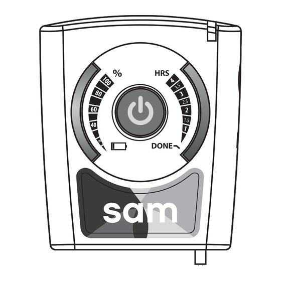
Page 9: Operator Interface
Bottom fi gure 2: sam Interface Components 7. Accessories Device may be used with any of the following accessories: Belt Clip Armband Carrying Case * Additional sam Ultrasound Coupling Bandages may be obtained by contacting the manufacturer Product Support 203-349-2798... -
Page 10: Led Display
Power Controller is OFF. No power is being generated Blue Power Controller is ON. Note – Ultrasonic energy is generated only when the Power Controller is connected to the sam Applicator(s) Green Power Controller battery is fully charged Amber Power Controller battery is charging Too many applicators are attached. - Page 11 Power Controller. Ultrasonic energy is being generated at all times this light is illuminated Red (accompanied by vibration) sam Sensing Mode. No Ultrasonic energy is being generated from this applicator while this light is illuminated Table 4. Applicator LED Color Defi nitions...
-
Page 12: Initial Setup Instructions
6 hours or until the Power Controller Indicator LED is Green. The Device arrives only partially charged due to generally accepted shipping practices. Bottom of sam Power Controller 9.1. CHARGING THE POWER CONTROLLER MODULE fi gure 3A A. Plug the micro USB end of the... - Page 13 10.2. TREATMENT LOCATIONS Figures 4 and 5 depict examples of device placement on two treatment locations. Figure Shoulder 4A and 4B illustrates using the Device with one applicator on the shoulder and knee. Figure 5A and 5B illustrates using the Device with two applicators on the shoulder and knee.
- Page 14 10.3.2. DUAL-APPLICATOR MODE The Y-adapter (optional) may be used to power two Applicators simultaneously. As shown in Figure 8, connect the Y-adapter directly to the Power Controller wire and then connect each Applicator to a wire jack at the other end of the Y-adapter. When using two Applicators and two Ultrasound Coupling Bandages...
-
Page 15: Application Instructions
11. Application Instructions 11.1. CHECK DEVICE CHARGE A. To prevent accidental activation during shipping, the device will arrive to the user in the ‘locked’ position. To unlock the device, slide the Lock Switch on the Power Controller ‘up’ into the ‘unlocked’ position (Figure 7A). - Page 16 11.2. CONNECT APPLICATOR TO POWER CONTROLLER * If using 2 applicators: fi rst connect the Y-adapter directly to the power controller wire jack and then connect each applicator to a wire jack at the other end of the Y-adapter (Figure 8*). A.
- Page 17 11.3. ATTACH APPLICATOR TO BANDAGE A. Remove the circular seal from the top of the bandage to reveal the coupling media within the gel cup (Figure 9A). B. Attach the applicator, face down, into the coupling media (Figure 9B). C. Firmly press the applicator down onto the center of the gel cup until a clicking noise is heard or clicking sensation is felt (Figure 9C).
- Page 18 11.4. APPLY ULTRASOUND COUPLING BANDAGE TO TREATMENT LOCATION A. Hold the applicator so the bottom of the bandage faces up. Remove the paper liner from the back of the bandage, revealing the bandage adhesive (Figure 10A). i. The circular seal should peel off the bottom of the gel cup along with the paper bandage liner.
- Page 19 11.5. TURN THE DEVICE ‘ON’ A. Check to make sure the Lock Switch is in Toggle the ‘unlocked’ position (Figure 11A). Button B. Press and hold the Power Button on Power Controller for at least 1 second to turn the device ‘ON’ (Figure 11B). i.
- Page 20 11.6. PREVENT UNINTENTIONAL SHUTOFF Once satisfi ed with the treatment settings, the settings may be locked to prevent unintentional shutoff during treatment by sliding the Lock Switch down into the ‘locked’ position as indicated by the symbols on the Power Controller (see Figure 11A).
-
Page 21: Device Power Down And Removal
12. Device Power Down and Removal 12.1. POWER OFF THE POWER CONTROLLER Move the Lock Switch up to the ‘unlocked position’ (if locked) then press and hold the Power Button on the Power Controller for at least 1 second to turn the device ‘OFF’... -
Page 22: Modes Of Operation
13. Modes of Operation 13.1. ON (UNLOCKED) MODE To turn the device ‘ON’, fi rst ensure the Lock Switch is in the unlocked position as indicated by the unlocked symbol on the Power Controller Module. Press and hold the Power Button for at least 1 second. Press the Toggle Button on the right side of the Power Controller Module to set the treatment duration. -
Page 23: Cleaning And Maintenance
13.4. SAM SENSING MODE In the event that the treatment site underneath the applicator reaches the temperature threshold, the applicator will pause ultrasound output and vibrate once with a red LED notifi cation to signify that the device has begun a cooling or rest cycle. -
Page 24: Storage And Operating Conditions
Store the sam Device in the following conditions: Temperature: 5-57 °C; Humidity: 10-80%; Atmospheric pressure range: 700-1060 hPa Store the sam Ultrasound Coupling Bandages in the following conditions: Temperature: 5-30 °C; Humidity: 10-80%; Atmospheric pressure range: 700-1060 hPa 15.2. OPERATION Only operate the sam Device in the following conditions: Temperature: 1-44 °C;... -
Page 25: Appendix
17. Appendix A. SYMBOLS Consult User Manual/Instructions for Use Manufacturer/Date of Manufacture Lithium-ion battery inside Li-ion Class BF Applied Part Do not use if package is damaged Do not reuse Non-ionizing radiation Separate collection for electrical and electronic equipment. Must not be disposed of in unsorted municipal waste. -
Page 26: Specifi Cations
B. SPECIFICATIONS Device does not contain microprocessor or software 0.65 W + 20% per transducer Maximum Acoustic 1.3 W + 20% for 2 transducers Power Output + 20% Maximum Intensity 0.132 W/cm 3 MHz + 20% Frequency Duty Cycle 100% - continuous wave Beam Form Wide Beam –... -
Page 27: C.notice Of Compliance, Calibration And Operational Period
Applicator 3.7 V DC + 10% Input Voltage: 3 MHz + 20% Ultrasound Frequency: 1 Transducer: 0.65 W + 20% Ultrasonic Output Power: 2 Transducers Together: 1.3 W + 20% Max Input Current: 400 mA Y-Adapter Voltage Rating 300 V 20°C Resistance 94/km C. -
Page 28: Technical Information
D. TECHNICAL INFORMATION fi gure A. Ultrasound Field Scan Across Applicator Face fi gure B. Ultrasound Field Scan Away From the Applicator Face figure B Ultrasound Field Scan Away From the Applicator Face ZetrOZ, Inc. Product Support 203-349-2798... -
Page 29: Electrical Immunity And Emissions
E. ELECTRICAL IMMUNITY AND EMISSIONS The following components of the sam Ultrasonic Diathermy Device are compliant with the requirements of IEC 60601-1-2 ed 3.0 (2007-03): sam Model 12 Cable Length AT-12: Ultrasound Applicators UB-12: Ultrasound Coupling Bandages 48 inches + 1.2 PMC-12: Power Controller Module 60 inches + 2.0... - Page 30 Guidance and Manufacturer’s Declaration – Immunity All ME Equipment and ME Systems is intended for use in the electromagnetic environment specifi ed below. The customer or user of the should ensure that it is used in such an environment. Immunity Test IEC 60601 Compliance Electromagnetic...
- Page 31 Guidance and Manufacturer’s Declaration – Immunity is intended for use in the electromagnetic environment specifi ed below. The customer or user of the sam should ensure that it is used in such an environment. Immunity Test IEC 60601 Compliance Electromagnetic...
-
Page 32: Warranty
Recommended Separation Distances between portable and mobile RF Communications equipment and the ME Equipment and ME Systems that are NOT Life-supporting is intended for use in the electromagnetic environment in which radiated disturbances are controlled. The customer or user of the can help prevent electromagnetic interference by maintaining a minimum distance between portable and mobile RF Communications Equipment and the... -
Page 33: Troubleshooting
G. TROUBLESHOOTING Question or Problem Solution 1. How to determine if As confi rmation that the device is delivering ultrasound, the device is delivering the LEDs on the Power Controller will illuminate blue treatment (treatment timer and indicator LEDs) and the indicator LED on the applicator will illuminate blue. - Page 34 G. TROUBLESHOOTING Question or Problem Solution 5. The Applicator is Turn off the device. Remove the Ultrasound Coupling not staying secured Bandage from the applicator. Replace with new during treatment Ultrasound Coupling Bandage. See section 11.3 for gel cup application instructions. 6.
- Page 35 Manufactured by ZetrOZ, Inc. 56 Quarry Road Trumbull, CT 06611 Toll Free Tel 1-888-202-9831 USA User Manual (OM-12) — LL-2535-01 Rev.B Published 06/04/2014 0086...
Need help?
Do you have a question about the sam-12 and is the answer not in the manual?
Questions and answers
How to put unit into armband