
Summary of Contents for Hobby Lobby International TEL1600
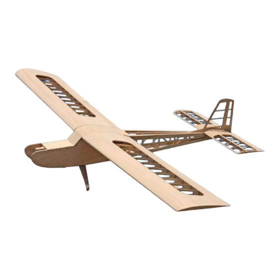
- Page 1 SENIOR TELEMASTER KIT TEL1600 Hobby Lobby International 5614 Franklin Pike Circle Brentwood TN 37027 USA Phone 866-512-1444 MADE IN THE USA TEL1600 -REV 1.13...
- Page 3 Terminology used in this manual. With the precision of laser cut parts and notch and tab construction, the assembly and gluing sequence becomes very im- portant. If components are glued in place to soon, they will not allow enough movement to install other components. When instructed to install a part, do only that.
-
Page 4: Wing Assembly
WING ASSEMBLY During the wing assembly you will be making several subassemblies. In some cases you will be making a left and right-handed assembly. It is best to make both assemblies at the same time in a mirror image of each other to minimize the possibility of making two assemblies of the same hand. - Page 5 c 4 The dihedral angle will be set by W1-B so it is important that W1-B be accurately fitted in position, Glue W1-B to the W1 assembly en- gaging the notch in W1-A. W1-B must be per- fectly flat against the W1 assembly. Use the building square to insure that W1-B is at 90°...
- Page 6 c 14 Loose fit all ribs into there appropriate notches in LEP, then use thin CA to glue them in and use the Building Square to insure that each rib is at 90° to the bench. Assure that all ribs are bottomed in there respective notches before applying glue.
- Page 7 c 19 Use a razor plane to shape the trailing edge of the ½” square into contour with the ribs. Use a short straight edge to guide material remov- al. Plane the tip to contour with the ribs and trailing edge as well. The trailing edge sheet will extend out to the wing tip.
- Page 8 c 24 Install and glue the two anti pivot PIN hatch screw rails (APHR) in the slots provided in ribs W1, W2 and W3. Use the following pro- cedure for a perfect fit. Lay the screw rails in the notches provided in W1, W2 and W3. Lay the hatch (PPHC) over these and align the screw holes.
- Page 9 The leading edge is checked with a straight edge for contour to the ribs in preparation for installing the leading edge sheeting. The leading edge is shaped to contour with all ribs and W1-IN in preparation for installing the top leading edge sheeting. c 29 Apply a bead of aliphatic resin glue to the leading edge of ribs W1 and W2 under the sheeting and along the entire leading edge.
- Page 10 c 30 Temporarily install the pivot pin hatch cover (PPHC) with some #2 screws. c 31 Before installing the top center section sheet- ing we will need to install and test the wing ANTIPIVOT pivot pin assembly. The pivot pin must move freely in the 3/16”...
- Page 11 c 36 The bottom wing tip sheeting is supplied in three pieces. Sections WTS-B and WTS-C must be glued to- gether before installation onto the wing. Glue WTS-A and the WTSB&C assembly into position. Shape the leading edge to contour using the c 37 supplied Leading Edge Template as a guide.
-
Page 12: Aileron Assembly
AILERON ASSEMBLY c 1 The ailerons and flaps are built over a base sheet so you do not need the plans to assemble these compo- nents. Once again. Be sure to assemble a LEFT and a RIGHT flap and aileron. Place one of the flap bases (FB) on the bench and glue in one horn block (HB) in the slot provided. - Page 13 c 14 Taper the leading and trailing edge to contour with the ribs in preparation for installing the top sheeting. c 15 Glue on the aileron top sheeting (AS). c 16 After finish sanding the aileron, the leading edge will need a double bevel, bevel the bot- tom (from the hinge line down) wit ha 15°...
-
Page 14: Stabilizer Assembly
STABILIZER ASSEMBLY To make the empennage easily removable, it has been designed with the servo’s integral to it. This makes the construction a little more complicated but is well worth the extra effort when removing the stabilizer/ rudder assembly. c 1 The stabilizer is built over the plans, cover the plans with waxed paper to protect them. c 2 The stabilizer base (SB) is supplied in two sections that must be assembled. - Page 15 c 5 Install the Stabilizer Servo Mount part B to SB in the same manner; there are two of these as well. c 6 Pin the SB assembly to the building board over the plans and install and glue the bottom spar. Slide a 1/8” x ½”...
-
Page 16: Servo Installation
SERVO INSTALLATION c 1 The servo mounts are installed onto the servo mount plate with Epoxy. Use the servo you plan to install as your guide for spacing of the mounts. c 2 When the Epoxy has set, mark and drill the holes for your servo. -
Page 17: Vertical Fin Assembly
c 2 Install and glue the elevator leading edge (ELE) Install and glue elevator ribs EVRA. You will need to taper the leading edge of these ribs to fit against EJ and the leading edge. Use some scrap 1/8” balsa to fill in against EJ to get more glue land. -
Page 18: Rudder Assembly
RUDDER ASSEMBLY The rudder horn block (R5) is laminated up from three pieces of 1/16” and 1/8” ply. Use the registration pins to assemble R5 from R5-A as the core with a R5-B on either side of that. This assembly will leave an internal slot to accept the removable tail wheel strut. - Page 19 c 10 The landing gear mount also serves as the hatch latch assembly. This latch arrangement can be servo actuated for cargo drops as well GM-E as manually accessed by a bolt that protrudes through the fuselage just ahead of the landing SPRING gear.
- Page 20 onto the spring. If it binds, you have it too NO GLUE IN THIS tight, back it off a quarter turn at a time till it AREA WIRE SPRING moves freely. This bolt will give you internal access to the hatch latch for servo operation. In the hole at the front of the latch tongue in- stall another #4-40 x 1”...
- Page 21 Assemble the bottom hatch frame assembly c 15 from FBH-A and FBH-C. Use the registration pins at both ends to position the parts. Apply glue to the hinge end (the end with all the holes in it) and a dab at the opposite end on the tab that contains the pinning hole.
- Page 22 c 22 Install one ¼” magnet into the hole provided in fuselage hatch latch plate (FLHP). Install and glue FLHP into the notches provided in the fuselage sides as well as F2. Cut a piece of ½” triangle stock and install c 23 and glue it into the notch provided at the windshield location.
- Page 23 c 31 Install and glue the top ¼” x 3/8” corner string- ers. The stringer should install flush with the top of the fuselage sides. Lay the center stringer in place and mark and c 32 remove the overlap material at the tail. Then glue the center stringer in place.
-
Page 24: Motor Mount Assembly
c 38 Cut four pieces if 3/32” x 4” balsa to fit the top of the fuselage in the wing area. Glue these into place start- ing at the windshield and terminating at F3. c 39 Temporarily install the empennage assembly with four #4-40 x 3/8” bolts. c 40 Glue the dorsal fin to the fuselage in line with the vertical fin and then remove the empennage assembly. -
Page 25: Landing Gear
LANDING GEAR For proper ground control a standard gear aircraft such as your Senior Telemaster should have toe in on the mains. As a general rule, the mains should be toed in so that they would meet about two and one half fuselage lengths in front of the aircraft. - Page 26 Part # Qty. Sheet Size Material Function Part # Qty. Sheet # Size Material Function 1/4" X 3" X 36" BALSA Aileron rib #1 1/8" X 4" X 36" BALSA Aileron rin #2 3/32" X 3" X 36" BALSA Aileron base 3/32"...
- Page 27 Part # Qty. Sheet Size Material Function 1/8" X 12" X 48" LITE PLY Fuselage former #7 1/8" X 12" X 48" LITE PLY Fuselage former #8 3/32" X 3" X 36" BALSA Flap base 3/32" X 3" X 36" BALSA Flap base FBH-D...
- Page 28 Part # Qty. Sheet Size Material Function 1/4" X 3" X 36" BALSA Rudder part #1 1/4" X 3" X 36" BALSA Rudder part #2 1/4" X 3" X 36" BALSA Rudder part #3 1/4" X 3" X 36" BALSA Rudder part #4 R5-A 1/8"...
- Page 29 Part # Qty. Sheet Size Material Function 1/4" X 3" X 36" BALSA Vertical fin part #3 1/4" X 3" X 36" BALSA Vertical fin part #4 1/4" X 3" X 36" BALSA Vertical fin paret #1 1/8" X 4" X 36" BALSA Wing rib #10 1/8"...
- Page 30 Part # Qty. Sheet Size Material Function 1/4" X 3" X 36" BALSA Wind shield 1/8" X 12" X 48" LITE PLY Wing servo mount 3/32" X 3" X 36" BALSA Wing sheer webs 3/32" X 3" X 36" BALSA Wing sheer webs 3/32"...
- Page 31 Inventory check off sheet Sheet # Size Material 1/16" X 3.8" X 11.6" AC PLY 1/16" X 3" X 36" BALSA 1/32" X 3" X 36" BALSA 1/16" X 3" X 36" BALSA 1/4" x 3" x 36" BALSA 1/4" X 3" X 36" BALSA 1/4"...
- Page 32 Music wire Tail wheel Threaded rod #2-56" x 12" Steel All control surfaces Wire .02" x 3.375" Latch spring Wire 1/16" x 5" Music wire Hatch hinge pin Hobby Lobby International 5614 Franklin Pike Circle Brentwood TN 37027 USA Phone 866-512-1444...
Need help?
Do you have a question about the TEL1600 and is the answer not in the manual?
Questions and answers
Need plans for TEL 1600. Happy to pay for plans & postage
The plans for the Hobby Lobby International TEL1600 are included in the manual. However, due to changes in temperature and humidity, the paper plans may slightly change in size. Align the slot in TEP with W2 on the plans and use them only for alignment, as the parts themselves are correct.
This answer is automatically generated