Table of Contents
Advertisement
Advertisement
Table of Contents

Related Manuals for Prusa Original Prusa i3 MK2


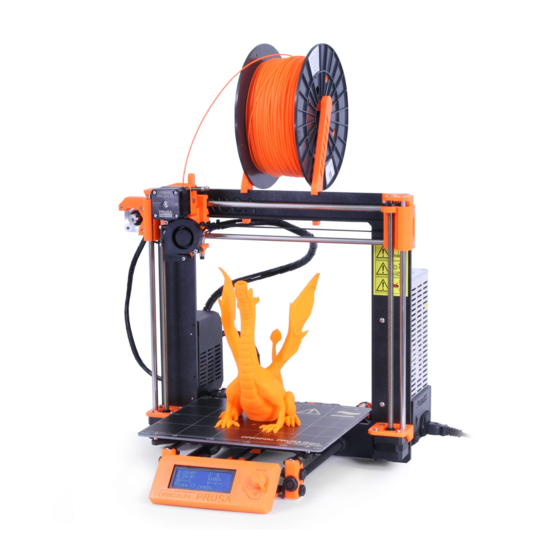
Summary of Contents for Prusa Original Prusa i3 MK2
-
Page 2: First Print
QUICK GUIDE TO THE FIRST PRINT 1. Place the printer on a flat and stable surface (page 11) 2. Read the safety instructions carefully (page 7) 3. Download and install the drivers (page 27) 4. Prepare the print surface (page 11), run selftest (page 13) and calibrate the printer (page 14) 5. Insert SD into the printer and print your first model (page 20, page 29) Handbook version 1.03 from June 19th, 2016. © Prusa Research s.r.o. 2 ... -
Page 3: About The Author
About the author rd Josef Prusa (born Feb 23 , 1990) became interested in the 3D printing phenomenon before joining the Prague’s University of Economics in 2009 at first it was a hobby, a new technology open to changes and improvements. The hobby soon became a passion and Josef grew into one of the leading developers of Adrien Bowyer’s international, open source, RepRap project. Today, you can see the Prusa design in different versions all around the world, it is one of the most popular printers and thanks to it, knowledge about the 3D printing technology significantly increased among public. Jo’s work on selfreplicating printers (you can print the other printer parts with your printer) are still ongoing and currently there is Prusa i3 the third iteration of the original 3D printer. It is constantly updated with the latest innovations and you've just purchased its latest version. In addition to printer hardware upgrades, the main goal is to make the technology more accessible and understandable for all users. Josef Prusa also organizes workshops for the public, participates in professional conferences dedicated to the popularization of 3D printing. For example, he lectured at the TEDx conference in Prague and Vienna, at World Maker Faire in New York, Maker Faire in Rome or at the Open Hardware Summit hosted by MIT. Josef also teaches Arduino at Charles University and was also a lecturer at the Academy of Arts in Prague. In his own words, he imagines 3D printers will be available in every home in a not too distant future. If anything is needed, you can simply print it. In this field, you just push the boundaries every day... We're glad you're part of it with us! 3 ... -
Page 4: Table Of Contents
Table of contents About the author 3 Table of contents 4 2 Product details 6 3 Introduction 6 3.1 Glossary 6 3.2 Disclaimer 7 3.3 Safety instructions 7 3.4 Licenses 7 4 Original Prusa i3 MK2 printer 8 5 Original Prusa i3 MK2 printer kit 9 6 First steps 10 6.1 Printer unpacking and proper handling 10 6.2 Printer assembly 11 6.3 Setup before printing 11 6.3.1 PEI print surface preparation 11 6.3.2 Increasing the adhesion 12 6.3.3 Plugging the AC power 13 6.3.4 Selftest 13 ... - Page 5 9.3 Slic3r 28 9.4 Bundled 3D models 29 9.5 Print in color with ColorPrint 30 9.6 Printing of nonstandard models 32 9.6.1 Printing with support material 32 9.6.2 Large object printing 33 10 Materials 34 10.1 ABS 34 10.2 PLA 34 10.3 PET 34 10.4 HIPS 34 10.5 PP 34 10.6 Nylon (Taulman Bridge) 34 10.7 Flex 35 11 FAQ Printer maintenance and print issues 36 11.1 Print surface preparation 36 11.2 Clogged / jammed extruder 36 11.3 Nozzle cleaning 37 11.4 Replacing / changing the nozzle 37 11.5 Axis fluency 38 ...
-
Page 6: Product Details
Power supply: 90135 VAC, 2 A / 180264 VAC, 1 A (5060 Hz) Working temperature range: 18 °C (PLA)38 °C, indoor use only Working humidity: 85 % or less Kit weight (brutto / netto): 9.8 kg / 6.3 kg, assembled printer weight (brutto / netto): 12 kg / 6.3 kg. Serial number is located on the printer control unit and also on the packaging. 3 Introduction Thank you for purchasing our original 3D p rinter O riginal Prusa i3 MK2 f rom Josef Prusa either as an assembled p rinter or a p rinter kit as your purchase supports us with its further development. Read the handbook carefully, please, all chapters contain valuable info for the correct service of the p rinter . Please check the h ttp://prusa3d.com/drivers page for updated version of this 3D printing hanbook (PDF download). ... -
Page 7: Disclaimer
3.4 Licenses Original Prusa i3 MK2 p rinter is a part of the RepRap project, the first open source 3D p rinter project free to use under a G NU G PL v3 l icense ( w ww. g nu . org/ l icenses / g pl 3.0.en.html ) . If ... -
Page 8: Original Prusa I3 Mk2 Printer
4 Original Prusa i3 MK2 printer Unlike the p rinter kit, it’s completely assembled and almost ready to p rint . After plugging in and running the necessary calibration you, can p rint a 3D object in the matter of minutes after unpacking the p rinter . Keep in mind you can use our s upport email when you purchased the assembled p rinter . Do not hesitate to write us if you need any advice or help. We will gladly help with any specific prints. 3D printers use two different diameters of a f ilament (you can find more in chapter ... -
Page 9: Original Prusa I3 Mk2 Printer Kit
5 Original Prusa i3 MK2 printer kit Original Prusa i3 MK2 kit is pictured in p i ct . 2. D etailed information and assembly description can be found in chapter 6 .2 Printer assembly . We offer the s upport for users who purchased the p rinter kit through our official forum. If you need help do not hesitate to visit our forum at f orum.prusa3d.com . You can find the answers for your problem there. If not, please just post your question directly there. ... -
Page 10: First Steps
6 First steps 6.1 Printer unpacking and proper handling Holding the upper frame, take the printer and pull it out from the box. Be careful when handling the p rinter not to damage the electronics and thus the p roper p rinter functionality. Anytime you move the p rinter, always hold the upper frame with hotbed upright pointing away from you as pictured in p i ct . 3 . ... -
Page 11: Printer Assembly
6.2 Printer assembly With Original Prusa i3 MK2 p rinter kit we suggest to follow the guidelines and assemble the kit according to the the o nline manual at m anual.prusa3d.com . ( O nline manual is available in several languages on the website). The construction of the printer should not take more than one working day. After a successful completion continue to the chapter 6 .3 Setup before printing . 6.3 Setup before printing ● Place the p rinter to a horizontally stable position, best place is a workbench where ... -
Page 12: Increasing The Adhesion
6.3.2 Increasing the adhesion In some special occasions, like a tall object with a very small contact area with the print surface, you might need to increase the adhesion. Fortunately PEI is a very chemically resistant polymer and you can temporary apply other adhesion solutions without damaging it. This also applies to materials which would not stick to PEI otherwise, like Nylon etc. Before applying anything to the bed, consider using B rim option in Slic3r which increases the surface area of the first layer. For PLA and Nylon blends a simple glue stick does the trick. Glue can be later easily removed by window cleaner or dish soap water. For ABS prints, ABS juice can be used and later cleaned with pure acetone. Be very gentle when applying the juice and do so while the bed is cold. Prints will attach very strongly. Prepared j uice can be also purchased in our eshop. Unfortunately, UPS service does not allow to deliver any acetonebased products due to shipping constraints. In that case you get only the bottle and ABS from our eshop and you have to source the acetone locally. Pic. 4 A BS Juice can be used to i ncrease the adhesion ... -
Page 13: Plugging The Ac Power
6.3.3 Plugging the AC power ● Plug in the AC power cord, check to make sure the proper setting for AC voltage is selected (110V/220V) and turn on the switch. 6.3.4 Selftest The purpose of the selftest routine is to check most common errors when assembling and connecting electronics and to help indicate any possible errors after assembly. You can run the S elftest f rom S ettings m enu on LCD panel. This should not be necessary on the assembled printers as those are pretested. Initiating this routine performs a series of tests. The progress and results of each step are displayed on the LCD. In case of errors found, the selftest is interrupted and the reason for error is shown to guide users in troubleshooting. Test consists of Heatbed and h otend proper wiring XYZ motors... -
Page 14: Preparing The Z Calibration
6.3.5 Preparing the Z Calibration The Original Prusa i3 MK2 comes with a full mesh bed leveling feature, however for this to work we need to first calibrate the distance between tip of the nozzle and P.I.N.D.A ( P r usa IND u ction A u toleveling) probe. The process is fairly straightforward, so let’s get to it. 6.3.5.1 Checking the Y‐Axis (kit only) For autocalibration to work properly, it is extremely important for the Y axis to be perpendicular to the X axis. This can be easily checked by looking at the printer from the top and visually aligning the Xaxis rods with lines on the heatbed. You can see it on the next picture. If the Y axis is misaligned, you can easily adjust the position of the Y axis inside the frame by loosening the M 10 nuts on the Y axis and securing them at the newly adjusted position. ... - Page 15 Pic. 6 The top of the probe should be aligned with the bottom of a printed part When you run the C alibrate Z f eature from the S ettings menu on the LCD panel, the printer will run the calibration routine. Closely watch how the probe approaches the 9 calibration points. 1st and the last points are marked with white dashed circles for easy recognition. The probe must be inside those circles to successfully calibrate. The nozzle must not touch the print surface during this cold calibration. I f it bends the print surface OR the probe is not inside the circles, it is wrong and you have to readjust the P.I.N.D.A probe! Only then you should continue with the calibration process. If you’re having trouble, feel free to ask us for help. If the problem is not taken care of during the cold calibration, the nozzle will p ermanently damage the print surface when hot. Pic. 7 The probe must be inside the circles to successfully calibrate . ...
-
Page 16: Checking The Z-Axis
6.3.5.3 Checking the Z‐axis It is extremely important for both XEND parts to be at the same height. This can be achieved by raising the Z axis until it hits the top from the LCD menu. Go to S ettings > Move axis > Move Z and rotate the knob until the axis reaches the top. Don’t worry, the motors do not have enough power to damage anything, but it will make the Z axis nice and straight. Pic. 8 It is extremely important for both XEND parts to be at the same height If there is any misalignment, it will cause the printer to touch the print surface with the nozzle typically on the 3 calibration points on the right side. 16 ... -
Page 17: Loading The Filament Into The Extruder
6.3.6 Loading the filament into the extruder ● Press the LCDknob to enter the main menu on the LCD. Rotate the button to choose Preheat o ption and confirm by pressing the LCDknob. Next you choose the m aterial you will p rint from. Choose a m aterial then confirm with LCDknob. The nozzle and heatbed will heat to the requested temperature. ● You need to p reheat the n ozzle before inserting the f ilament (and the bed too if you like to ... -
Page 18: Z Calibration
6.3.7 Z Calibration NOTE: The calibration process has been made easier and is now called V2 Calibration. If the V 2Calibration.gcode is not present on your SD card you can easily obtain it from our support or on our h ttp://www.prusa3d.com/drivers/ page. Check if your print surface is clean! Y ou can find instructions how to clean it in the chapter 6 .3.1 PEI print surface preparation . Don't forget to complete 6 .3.5 Preparing the Z Calibration chapter or y ou can permanently damage the print surface ! Now we will finally calibrate the distance between tip of the nozzle and the probe. Preheat ... -
Page 19: Finetuning The Z Adjustment
6.3.7.1 Finetuning the Z adjustment After finishing the calibration gcode, it is a good idea to print a simple object. The Prusa gcode from the supplied SD card is a great example. The L ive adjust Z function works during every print, so you can finetune at any point. You can see the properly tuned first layer on the images below. Pict. 11 The properly tuned first layer Now you are done! 6.3.7.2 Securing of the probe (kit only) After couple of prints ideally secure the bottom nut on the probe with a drop of Loctite 243 (Blue Threadlocker) to prevent loosening over time. Pict. 12 secure the bottom nut on the probe with a drop of Loctite 243 19 ... -
Page 20: Printing
7 Printing ● Make sure that the n ozzle and the bed are heated to the desired temperature. If you forget to p reheat the p rinting n ozzle and the bed before p rinting, the p rinter will automatically check the temperatures of the n ozzle and the bed; p rinting will start when desired temperature is reached it can take several minutes. However, we ... -
Page 21: Printer Control
Pict. 14 LCD layout 1. Nozzle temperature (actual / desired temperature) 2. Heatbed temperature (actual / desired temperature) 3. Progress of p rinting in % shown only during the p rinting 4. Status bar (Prusa i3 MK ready / H eating / model_name.gcode, etc.) 5. Zaxis position 6. Printing s peed 7. Elapsed p rinting time shown only when p rinting 7.1.2 Print statistics The printer tracks printing statistics. When you access this option during a print, you will see ... -
Page 22: Silent Vs. Hi-Power Mode
7.1.2 Silent vs. Hi‐power mode The printer offers two settings for motor power consumption. Silent uses less current and makes the printer quieter, but less powerful. Hipower is great for very large (over 200 gram) prints and for freshly assembled kits before you fine tune everything. If you experience lost steps (shifted layers), use Hipower mode. 7.1.3 Factory reset Printer can be reset to factory settings, for example if you select wrong language and can’t locate the language settings menu. 1. Printer must be powered on. 2. Press and hold the rotary selector 3. Press and release the reset switch marked with X directly below the rotary selector 4. The printer will indicate a successful reset by beeping. You can then release the rotary selector and wait for the printer to boot up. 7.1.4 LCD layout Items not mentioned below are not used for the common p rint setup you should not change any of the unmentioned i tems unless you are absolutely sure what you are doing. ... - Page 23 ❏ FLEX 230/50 ❏ Cooldown ❏ Print from SD ❏ Load f ilament ❏ Unload f ilament ❏ Settings ❏ Temperature ❏ Nozzle ❏ Bed ❏ Fan speed ❏ Move axis ❏ Move X ❏ Move Y ❏ Move Z ❏ Extruder ❏ Calibrate Z ❏ Disable steppers ❏ Auto home ❏...
-
Page 24: Print Speed Versus Print Quality
When increasing the speed always check the model is cooled properly especially when printing small object from ABS increased speed causes the distortion (sometimes called “warping”) of the model. You can prevent this issue by printing more similar objects together layer printing interval is long enough to prevent this issue. If the model shows lower quality than desired you can decrease the printing speed turn the LCDknob counterclockwise. Minimum usable printing speed is around 20 % of nominal speed. 7.1.6 USB cable and Pronterface We strongly recommend to use LCD panel while printing on Prusa i3 MK2 Pronterface doesn’t support all functions of a new firmware (e.g. filament change while printing). Keep in mind that when printing from the Pronterface the c omputer must be connected to the p rinter during the whole p rinting process computer must be prevented from sleep, hibernation or shutting down. Disconnecting the computer during the p rint ends the p rinting without the option to finish the object. ... - Page 25 Pict. 16 You can find USB port here ● Choose connection port in Pronterface (download available with the p rinter drivers, ) : Mac users use / usbmodem port, PC Windows see the chapter 8 Printer drivers ports are COM1, COM2, etc.; the correct port is displayed in device manager, Linux users c onnect the p rinter using the virtual serial port. When the p rinter is connected click the C onnect b utton. Right column shows the connection information. ●...
-
Page 26: Printer Addons
8. Confirming the set temperatures, h eating start. 9. 2D p rint process preview. 10. Info panel. Estimated p rint time, axis position and other info is displayed after l oading the m odel . 7.2 Printer addons 7.2.1 Different nozzles E3D, a UK based company, supplies hotends for the Original Prusa i3 MK2 has whole ecosystem of upgrades and addons. We support some of them. You can check out how to change the nozzle in section 1 1.4 Replacing / changing the nozzle. ... -
Page 27: Hardened Steel Nozzle
Slic3r preparing the 3D m odels to .gcode format for p rinting . Pronterface p rinting from a computer (in case you don’t want to p rint from SD) NetFabb repairing the corrupted or unprintable m odels Settings o ptimized p rint s ettings for Slic3r, Cura, Simplify3D and KISSlicer Drivers for Prusa i3 printer Windows a Mac drivers Test objects 9 Printing your own models ... -
Page 28: In What Program You Can Create Your Own Models
9.2 In what program you can create your own models? To create a 3D m odel yourself, you need a dedicated program. The easiest way to quickly create a m odel is T inkerCad ( w ww. t inkercad . com ) an o nline editor (no installation needed) you create your 3D m odel directly in the browser window. It is free, is easy to operate and you will find even basic video tutorials, so after a few minutes nothing prevents you to create ... -
Page 29: Bundled 3D Models
Pict. 19 Slic3r interface 1. Add button loads models into Slic3r. 2. Delete and D elete All buttons remove the m odel ( s) from Slic3r. 3. Opens the d etailed s ettings of p rint , f ilament and p rinter . 4. -
Page 30: Print In Color With Colorprint
Pict. 21 Multicolored object printed with ColorPrint ColorPrint will not work correctly if your print settings c ontain hop or zlift. The app detects layers in gcode by tracking increase in Z height and the hop/zlift does that multiple times in the same layer. Turn off this setting before using ColorPrint. The preconfigured Slic3r in our drivers offers the O riginal Prusa i3 MK2 ColorPrint option in printer selection. ● First of all you need to prepare regular g code with common print and filament settings. Save the file. ● Then go to w ww.prusaprinters.org and choose C olor Print in the header menu. ● Drag the gcode to frame and click on A dd change b utton. ● Find the h eight of the layer where you want to make the color change. This can be ... - Page 31 Insert the filament which you want to start with into your printer and start printing the file. When the color change is triggered from the gcode the printer will follow simple procedure: ● Stop moving and retract ● Raise the Z by 2 mm and move quickly outside the printbed ● Unload the current filament ● You will get asked to insert the new filament. When you do so and continue, filament will be pulled into the hotend and LCD will display “ Changed correctly?” w ith three options: 1. “Yes” Everything went ok and p rinting can continue. Check if the new c olor is clear without any remains of the previous f ilament if yes, choose this option to continue printing with a new c olor . 2.
-
Page 32: Printing Of Non-Standard Models
Other options for m ulticolored p rint i s to u se the f ilament change option. Choose the T une a nd then C hange f ilament option during the p rint . Printer will pause the printing process, unload the f ilament and signals you to insert the new f ilament . The procedure is the same as above. ... -
Page 33: Large Object Printing
9.6.2 Large object printing Another special p rinting case is when p rinting objects larger than the h eatbed . First option is to resize the object to a printable s ize . Rightclick on an object in Slic3r opens a menu with the S cale … o ption, then you choose U niformly , if you want to s cale down the m odel evenly; or you can alter the ... -
Page 34: Materials
10 Materials Temperatures and the h eatbed treatment before p rint according to a specific m aterial . 10.1 ABS Material suitable for common, robust objects. ● Nozzle temperature: 2 55 ° C ● Bed temperature: 1 00 °C. You can set the bed temperature between 80 to 110 °C depending the s ize of an object (larger object means higher temperature) ● Heatbed: M ake sure the surface is clean as described in 6 .3.1 PEI print surface ... -
Page 35: Flex
10.7 Flex Flex is a very strong and flexible m aterial suitable especially for the flexible prototypes, covers, etc. I mportant: Before you start printing from Flex, clean the nozzle from the previous material preheat the nozzle and load PLA to remove any other previous material. When loading Flex loosen the extruder (idler) screws. Keep in mind that when printing from Flex the automatic filament exchange function may not work properly. ● Nozzle temperature: 2 30 °C ● Bed temperature: 5 0 °C. You can set the bed temperature up to 65 °C depending the s ize of an object. (larger object means higher temperature) ● Heatbed: M ake sure the surface is clean as described in 6 .3.1 PEI print surface preparation chapter ... -
Page 36: Faq - Printer Maintenance And Print Issues
11 FAQ ‐ Printer maintenance and print issues 11.1 Print surface preparation Print surface preparation is described in 6 .3.1 PEI print surface preparation chapter. 11.2 Clogged / jammed extruder Material clogged in the extruder can cause problems with the p rinting or with the l oading of a new f ilament . ● Heat the nozzle, remove the filament from the extruder and cut the rod cca 10 cm above the damaged part. ... -
Page 37: Nozzle Cleaning
11.3 Nozzle cleaning Use a wire brush to clean the n ozzle from outside. Heat the n ozzle before you do so. If f ilament is not extruded from a n ozzle (or in very small volume), first check the extruder fan is working p roperly and that the temperature is set correctly (PLA 210 °C; ABS 255 °C, HIPS 220 °C, PET 240 °C). Also check that the f ilament was correctly loaded into the extruder. If the f ilament pours out at least a little, check the direction. If it swirls and goes up to the hotend you need to clean the n ozzle . First you have to move the extruder to the rightmost position, out of the way of the ... -
Page 38: Axis Fluency
Pict. 29 N ozzle change 11.5 Axis fluency ● If one of the axes doesn’t move fluidly you can apply a small amount of oil (e.g. all purpose machine oil). This will lower the friction. 38 ... -
Page 39: Printing Problems
11.5 Printing problems 11.5.1 Layers break and split when printing from ABS material ABS m aterial has a higher thermal expansion than other m aterials . We suggest other materials as PET, HIPS or PLA when you p rint larger m odels . 11.5.2 Models contain either too much or not enough of the filament ... -
Page 40: Faq - Common Issues When Assembling The Printer Kit
12 FAQ ‐ common issues when assembling the printer kit 12.1 Nozzle/print surface gap is greater in the middle than at the corners The reason of this issue isn’t the bent printer surface or bed but a distorted Yaxis. We suggest to remove the whole Yaxis out of the p rinter . Follow these steps: ● Align the Yaxis so that each Ycorner is sitting on the table none should be off the table. ● Align the tightening of each Yaxis threaded rod so that each Ycorner is perpendicular (facing upright) to the table surface. ● Align the tightening of each Yaxis threaded rod so that each M8 threaded rod is at a right angle to the M10 threaded rods the Yaxis must form a perfect rectangle when ... -
Page 41: Printer Stops Printing Soon After Start
12.2 Printer stops printing soon after start Extruder is likely overheated. Make sure the n ozzle fan is working p roperly . If not, please inspect its connection according to the assembly manual. Pict. 31 P roper wiring of the connectors 12.3 Printer can’t read SD card First, make sure that the f ile name on the SD d oes not contain special characters otherwise the file could not be displayed on LCD. If there is no error in the file name, check ... -
Page 42: Loose X- And/Or Y-Axis Belts
12.4 Loose X‐ and/or Y‐axis belts Check if both belts are p roperly tightened, loose belts would cause a p rinter malfunction and prevent p roper p rinting . The easiest way to check is p rinting a round object if any of the belts are not tightened p roperly the result is an irregular shape instead of a perfect circle. Yaxis belt is located under the h eatbed , Xaxis belt moves the extruder. See the pictures with ... -
Page 43: Detached Cables To The Heatbed
12.5 Detached cables to the heatbed Do not forget to use a spiral wrap on h eatbed c ables and attach the c ables p roperly so they won’t restrict movement during printing. Pict. 34 C ables to be wrapped in a spiral wrap 12.6 Loose heatbed zipties ... - Page 44 Notes: ...
Need help?
Do you have a question about the Original Prusa i3 MK2 and is the answer not in the manual?
Questions and answers