
Related Manuals for Alfamacchine MINIGRAF M3

Summary of Contents for Alfamacchine MINIGRAF M3
- Page 1 Minigraf M3 INSTRUCTION HANDBOOK MINIGRAF 3 Alfamacchine Via dell’Artigiano, 12 - 47100 Forlì - Italy Tel. +39-0543-482711 - Fax +39-0543-480770 info@alfamacchine.com - www.alfamacchine.com...
-
Page 2: Table Of Contents
Minigraf M3 7.7.2 V-nail guide head replacement to change INDEX V-nails size 4.8 ADJUSTMENTS 4.8.1 V-nails inserting positions adjustment 4.8.2 Vertical clamp adjustment 1. GENERAL INFORMATION 4.8.2a Vertical clamp position adjustment 1.1 PRODUCER 4.8.2b Vertical clamp height adjustment 1.2 ASSISTANCE CENTERS 1.3 CERTIFICATION... -
Page 3: General Information
1. GENERAL INFORMATION PRODUCER The warranty decays in case of unauthorized modifications The firm Alfamacchine can boast more than 10 years of or because of accidental damages or tampering performed experience in the construction of Woodworking Machines. by unqualified personnel. -
Page 4: Symbols Utilized
Minigraf M3 1.6.4 Symbols utilized It indicates a danger with a mortal risk for the operator DANGER P... It indicates a warning or a note about key functions or useful information. Pay the maximum attention to the paragraph WARNING marked with this symbol. -
Page 5: Machine Description
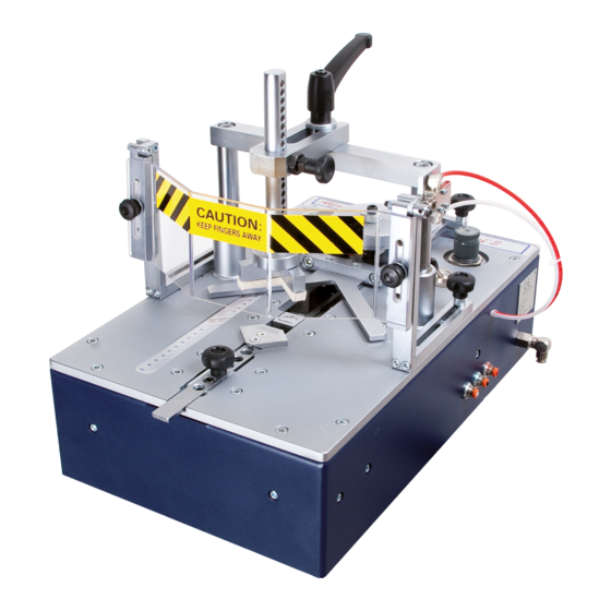
Minigraf M3 2. MACHINE DESCRIPTION WORKING PRINCIPLE DIMENSIONS The benchtop Frame Assembling Machine Minigraf 3 has The overall dimensions are reported on table 2.9-A been realized to assemble any kind of frame. The Minigraf 3 being of simple construction and extremely... -
Page 6: Technical Data
Minigraf M3 TECHNICAL DATA We have listed below the Machine’s data and technical characteristics to which you can make reference for any eventual contact with your distributor for Technical Assistance. TABLE 2. 9 A Tecnical data Frames thickness min-max 6-80 mm. -
Page 7: Customized Optional Accessories
Minigraf M3 2.10.4 Customized optional accessories Thanks to its versatility this machine can be ‘custom-made’ to meet our users requirements, with additional accessories that can make the frame assembling easier: e.g. special fences for peculiar moulding shapes, special clamps to ensure the mouldings are locked properly during V-nail firing, and so on. -
Page 8: Safety
The area where the frames are assembled is defined as the adequate training to be instructed by your “working area” local distributor or ALFAMACCHINE’s The dangerous areas of machine, include the movable parts technicians. The other risks related with using the machine are:... -
Page 9: Residual Risks
Minigraf M3 RESIDUAL RISKS 4. INSTALLATION During the normal working cycle and while performing SHIPPING AND HANDLING maintenance the operators are exposed to several residual The shipment must be performed by a professionally qualified risks that because of the operations own nature can not be staff. -
Page 10: Preliminary Arrangements
Shipping damages or any other defects must compressor system. You could use also another fitting be reported to Alfamacchine or your local distributor within suitable with your pneumatic system (see fig. 6). 3 days from receipt of the machine. -
Page 11: Preliminary Controls
Minigraf M3 PRELIMINARY CONTROLS The preliminary operations before starting the machine, must be executed by a technician appointed by the customer. Before setting up the machine, it is necessary to execute certain verifications and checks to prevent mistakes or accidents during setup. -
Page 12: Adjustments
Minigraf M3 ADJUSTMENTS The machine has been completely tested and checked in ALFAMACCHINE’s plants before its shipment. All the operator has to do is perform the following adjustments: 4.8.1 V-nails inserting positions adjustment To properly position the mouldings to be assembled, the Minigraf 3 is equipped with a 90°... -
Page 13: Vertical Clamp Adjustment
Minigraf M3 4.8.2 Vertical clamp adjustment The vertical clamp can be adjusted in height and position. Proceed as follows to adjust them: 4.8.2a Vertical clamp position adjustment • Position the mouldings to be assembled on the working bench • Select the pressure pad suitable with the profile of the moulding to be assembled and put it on the vertical bar •... -
Page 14: Working Pressure Adjustment
Minigraf M3 Picture 18 Picture 19 In case of continued use without needing to remove the frontal clamp from its DO NOT ADJUST the pressure position, it is possible to fix it into the peg if the machine is not connected to using the proper screw. -
Page 15: Protective Shield Adjustment
Minigraf M3 4.8.5 Protective shield adjustment CHECKING OPERATIONS TO BE You can order a protective shield made of transparent plastic EFFECTED BEFORE WORKING START material. (see fig. 20). Once the machine has been properly installed (like previously described), check that:... -
Page 16: Functioning
Minigraf M3 5. FUNCTIONING TIPS FOR PERFECT JUNCTIONS V-nail types OPERATORS In order to allow the machine to make excellent quality joints The machine has been projected to be used by only one using different materials, it has been necessary to operator. -
Page 17: Putting Out Of Service
Minigraf M3 PUTTING OUT OF SERVICE In case on long inactivity periods it is necessary to disconnect the fast clutch fitting from pneumatic system. 6. MAINTENANCE STATE OF MAINTENANCE The maintenance operations must be performed with the machine in the conditions described at “state of the machine”... -
Page 18: Lubrication
EXTRAORDINARY MAINTENANCE Listed below are the operations that need the intervention of Alfamacchine or your local distributor’s Technical Assistance (see the paragraph 1.2). You can also use qualified staff authorized by the Producer The extraordinary maintenance includes interventions to be performed in exceptional cases: •... -
Page 19: Diagnostic
Minigraf M3 7. DIAGNOSTIC SAFETY WARNINGS The interventions must be executed by personnel properly trained and they must take all precautions in order to avoid accidental starts. TROUBLESHOOTING TABLE 7. 2 - A POSSIBLE CAUSE REMEDY TROUBLE Insufficient working pressure... -
Page 20: Request Of Assistance
Minigraf M3 POSSIBLE CAUSE REMEDY TROUBLE Faulty or jammed valves Pressing the foot pedal the machine - Remove the surplus of oil and/or condensation works properly, but once the pedal is - Replace the foot pedal valve released you can note a certain delay in... -
Page 21: Spare Parts
We remind you that only a qualified technician can repair the machine. Therefore we suggest the intervention of your local distributor or ALFAMACCHINE’s Center of Technical Assistance, which has access to qualified staff, proper equipment and tools, and who uses original spare parts. - Page 22 Minigraf M3 SCHEMES A - Mechanic Schemes (code: DWG Nr. 003.0.100 Rev.1/01-1997)
- Page 23 Minigraf M3 Head Ref. Description Screw Complete cylinder Handle Cylinder Washer Bracket Support Feeder cylinder Screw Staples box Screw Screw Handle Complete pin Knob Stapples pusher Support Screw Complete brake Head Gasket Head H7 Washer Head H10 Pressure gauge Head H15...
- Page 24 Minigraf M3 SCHEMES B - Pneumatic Scheme Ref. Description Regulator Pressure Gauge Valve 228.52.11.1 (or 2411520016) Valve 228.52.11.1 (or 2411520016) Pressure Regulator Valve 0ALF 100...
- Page 25 Minigraf M3 SCHEME C - Plates location...
- Page 26 Minigraf M3 SCHEMES D - Sharpening Table SOFT WOOD HARD WOOD Very soft Soft wood Height Averaged Averaged Very hard Hard wood wwod soft wood hard wood wood <> <> <> H 3* mm H 5* mm H 7 mm...
Need help?
Do you have a question about the MINIGRAF M3 and is the answer not in the manual?
Questions and answers