Table of Contents
Advertisement
Quick Links
Advertisement
Table of Contents

Summary of Contents for KONICS krn100
-
Page 1: User Manual
USER MANUAL © Copyright Reserved KONICS Co., Ltd. - Page 2 © Copyright Reserved KONICS Co., Ltd.
-
Page 3: Preface
Preface Preface Thank you very much for selecting KONICS products. Please familiarize yourself with the information contained in the Safety Precautions section before using this product. This user manual contains information about the product and its proper use, and should be kept in a place where it will be easy to access. -
Page 4: User Manual Guide
The manual's content may vary depending on changes to the product's software and other unforeseen developments within KONICS, and is subject to change without prior notice. We contrived to describe this manual more easily and correctly. However, if there are any ... -
Page 5: User Manual Symbols
Failure to follow instructions can result in serious injury or death. Failure to follow instructions can lead to a minor injury or product damage. An example of the concerned feature's use. Annotation mark. ※1 © Copyright Reserved KONICS Co., Ltd. -
Page 6: Safety Precautions
AWG 20(0.50mm ). Terminal screw should be tightened with 0.74 N•m to 0.90 N•m torque. Please observe the rated specifications. It may cause shorten the life cycle of the product and cause a fire. © Copyright Reserved KONICS Co., Ltd. - Page 7 Use voltage output of transmitter power output card only for transmitter power. It may cause damage to output module. The specifications and dimensions of this manual are subject to change without any notice. © Copyright Reserved KONICS Co., Ltd.
-
Page 8: Table Of Contents
Checking driver ..................38 Display ....................... 39 Initial booting screen ..................39 Screen layout ..................... 40 6.2.1 Status display ..................... 40 6.2.2 Virtual keyboard ..................43 6.2.3 Parameter setting display ................44 Operation ....................45 viii © Copyright Reserved KONICS Co., Ltd. -
Page 9: Table Of Contents
DI-□ Reset No (Reset alarm number) ............88 8.3.4 DI-□ Status (Operation status) ..............88 COMMUNICATION SETUP (Communication setting) ........89 8.4.1 Modbus Address (Communication address) ..........92 8.4.2 RS485 Port (Use RS485 communication) ..........92 © Copyright Reserved KONICS Co., Ltd. - Page 10 8.7.1 Load Set File (Open parameter setting file) ..........121 8.7.2 Save Set File (Save parameter setting file) ..........121 8.7.3 Memory Status (Memory capacity) ............122 8.7.4 Memory Clear (Delete memory) ............... 122 © Copyright Reserved KONICS Co., Ltd.
- Page 11 Backup Print Mode (Backup data record mode) ........134 8.9.6 Select Print Mode (Backup data recording mode setting) ....... 135 DAQMaster ....................137 Overview ......................137 Features ......................138 Dedicated KRN100 functions ................139 9.3.1 Record Backup ..................139 9.3.2 User unit setting ..................140 9.3.3 Boot logo image setting ................
- Page 12 Table of Contents © Copyright Reserved KONICS Co., Ltd.
-
Page 13: Overview
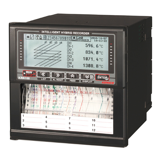
USB memory (the world’s first) and by adopting Trend graph, Bar graph, digital number display function through graphic LCD. KRN100 enables to print the saved data of system memory as data backup function when run out of recording paper. KRN100 improves convenience by parameter setting, data transmittion through RS485 and Ethernet communication (USB device is only for parameter setting), and backup data logger function. -
Page 14: Component And Sold Separately
1 Overview Component and sold separately 1.2.1 Component Before using KRN100, check the component. If any component is left out or damaged, contact our company or seller. KONICS service center: +82-32-820-2343 1.2.2 Accessory (1) I/O card (2) Communication converter Appearances of SCM-38I (RS232C to RS485 converter) and SCM-US48I (USB to RS485 converter) are same. -
Page 15: Ordering Information
⑥ ⑦ ⑧ ⑨ Item Description KRN100 New KONICS 100mm Paper Type Recorder ①Item 4 channel (KRN-UI2 X 2ea) 6 channel (KRN-UI2 X 3ea) 8 channel (KRN-UI2 X 4ea) ②Input channel 10 channel (KRN-UI2 X 5ea) 12 channel (KRN-UI2 X 6ea) None ③Digital input... - Page 16 4ea as mixed. (3) Example of ordering To use universal input 10 channel, digital input 4 channel, alarm relay output 5 channel, and RS485 communication output, it is ordered as KRN100-10102-01-0S and connected I/O card is as below. KRN100(Recorder): 1ea ...
-
Page 17: Part Description
Using this key for entering setting mode (3 sec) and set value change mode. ⑤ USB Host: Connects an USB memory. It recognizes max. 32Gbyte and if using cable, it is available up to 1.5m. © Copyright Reserved KONICS Co., Ltd. - Page 18 Function key: Use this key to enter virtual keyboard in parameter setting. Press key, and Function key appears on lower screen as below figure. Press , or key as below Function key, it operates the appropriate Function key’s operation. © Copyright Reserved KONICS Co., Ltd.
-
Page 19: Back Side
Slot(1 to 6) for connecting universal input card(KRN-UI2) ④ Power connecting part (100-240VAC, 50/60Hz) ※ Above back side image is connected every otuput card to help your understand. Factory default is only connected with universal input cards (Slot1 and 2). © Copyright Reserved KONICS Co., Ltd. -
Page 20: Inside
Front cover of recording paper storage: Open recording paper guide for recording paper replacement ④ New recording paper storage: Storage part for new recording paper (1EA recording paper is storable.) ⑤ Back cover of recording paper storage © Copyright Reserved KONICS Co., Ltd. -
Page 21: Specification
±2kV the square wave noise (pulse width 1µs) by the noise simulator Time accuracy Within ±2min/year (Enables to use up to 2100 year) Enables to normal print with going and returning printing max.5 times Mechanism cartridge within 7 days after opening the unit © Copyright Reserved KONICS Co., Ltd. - Page 22 Please do not use this unit at place with high humidity. Approval Unit weight Approx. 1.7 to 2.0kg ※1. For more information of universal input, please refer to ‘2.2 I/O card’. ※2. Environment resistance is rated at no freezing or condensation. © Copyright Reserved KONICS Co., Ltd.
-
Page 23: I/O Card
※ 3 Device ※ 4 ※1. To change input specification, you must turn OFF the power of KRN100, remove universal input card, set inner jumper pin (Please refer to 4.2 I/O card.) and re-connect it. © Copyright Reserved KONICS Co., Ltd. - Page 24 ※5. It is recommended to use shield cable to decrease noise when supplying power for transmitter. If connecting or disconnecting input/output card when power is ON, it may cause malfunction. To connect or disconnect input/output card, you must turn OFF the power. © Copyright Reserved KONICS Co., Ltd.
-
Page 25: Input Specification And Measuring Range
※2. G(TT): Same temperature sensor type as existing W(TT). ※3. Russian type L type temperature sensor is divided from general purpose L type. To change input specification, set jumper pin of KRN-UI2(Universal input card). (Please refer to ‘4.2 I/O card.) © Copyright Reserved KONICS Co., Ltd. - Page 26 2 Specification © Copyright Reserved KONICS Co., Ltd.
-
Page 27: Dimensions
3 Dimensions Dimensions (1) KRN100 ※ Back side dimension is with installed I/O cards to every slot. (2) Panel cut-out ※ Use panel which is 2 to 8mm thickness. © Copyright Reserved KONICS Co., Ltd. - Page 28 3 Dimensions © Copyright Reserved KONICS Co., Ltd.
-
Page 29: Connection
4 Connection Connection KRN100 This figure is back side of KRN100-04000-00-0S model. Slot Description 1 to 6 Connects universal input card (KRN-UI2). Connect digital input card (KRN-DI6), alarm output card (KRN-AR4, KRN-AT6), and 7 to 10 transmitter power output card (KRN-24V3). -
Page 30: I/O Card
4 Connection I/O card Universal input card (KRN-UI2) Digital input card (KRN-DI6) Alarm output card Alarm output card (KRN-AR4(Relay output)) (KRN-AT6(TR output)) Transmitter power output card Communication output card (KRN-COM) (KRN-24V3) © Copyright Reserved KONICS Co., Ltd. - Page 31 Input break alarm 0 to 20 ㎃, 4 to 20 ㎃ Enables only 4 to 20 ㎃ ① Enables TC, RTD, ±60mV, ±200mV ② Disables ±2V, 1 to 5V, ±5V, -1 to 10V ③ © Copyright Reserved KONICS Co., Ltd.
- Page 32 4 Connection © Copyright Reserved KONICS Co., Ltd.
-
Page 33: Installation
To prevent from malfunction and damage by overheating (use temperature range: 0 to 50℃), install this unit where ventilation is well. In case installing several KRN100, space each other by panel cut-out. Place where vibration is not severe ... -
Page 34: Installation
5 Installation Installation 5.2.1 Bracket mounting 1st Install KRN100 on the processed panel as panel cut-out diagram. Mount fixing brackets on upper/lower parts. 2nd Tighten fixing brackets on upper/lower parts to fix on the panel with phillips screwdriver (+). (Torque: 0.4N•m) -
Page 35: Additional I/O Card Connection
1st To connect I/O card additionally, turn OFF the power of KRN100. Remove the proper slot cover to insert I/O card with flat-head screwdriver or knife. 2nd Insert I/O card to the proper slot and turn ON the power of KRN100. © Copyright Reserved KONICS Co., Ltd. -
Page 36: Usb To Serial Driver
5 Installation USB to Serial driver Install USB to serial driver which is applied for KRN100 sereis and connect DAQMaster and you can set parameter setting.(It is available only when communication output card (KRN-COM) is connected. Supporing OS for USB to Serial driver is Windows XP 32/64bit, Windows 7 32/64bit.) 5.3.1... - Page 37 Click ‘Browse’ and select the folder which has 'KRN100_USB_Serial_Drivers’ and click ‘OK’. 5th If hardware compatibility message appears, click ‘Continue Anyway’ and it processes the next. 6th At ‘Completing the Found New Hardware Wizard’, click ‘Finish’ and driver installation is complete. © Copyright Reserved KONICS Co., Ltd.
-
Page 38: Checking Driver
To check the driver, right click 'My computer' and select 'Properties' on pop-up menu. 'System Properties' dialog appears. Select ‘Hardware’ tab and click 'Device Manager'. ‘Device Manager’dialog appears. Check ‘Ports(COM & LPT)’ - 'KRN100 USB To Serial Converter (COMx)'. © Copyright Reserved KONICS Co., Ltd. -
Page 39: Display
Below booting screens are initially displayed when power is supplied to KRN100. These screens progresses initial settings for KRN100 to operate normally and checks inner system memory. If there is no error for inner system memory, booting is finished and KRN100 operates normally. Screen for progressing initial setting ... -
Page 40: Screen Layout
Digital mode icon Marks it for digital record mode. Graph mode icon Marks it for graph record mode. Record memory status Marks it storage capacity of record memory in icon digital mode or graph mode. © Copyright Reserved KONICS Co., Ltd. - Page 41 Displays current date and time. In summer time Date/Time display season, (S) mark is also displayed at front of year. ※1. If there is no recording paper, icon flashes. After replacing recording paper, P.END BACKUP PRINT screen as below is activated. © Copyright Reserved KONICS Co., Ltd.
- Page 42 Backup data recording function by P.END is same as RECORD BACKUP. Backup Data List cannot be changed. Starting print by P.END Backup, it prints the data but backup data file date, file name, and backup record starting line. © Copyright Reserved KONICS Co., Ltd.
-
Page 43: Virtual Keyboard
Moves digit to select character of virtual keyboard Enters set characters ※1. Enterable characters are as below. English capital letters English small letters Special character ※2. Screen of Function key using © Copyright Reserved KONICS Co., Ltd. -
Page 44: Parameter Setting Display
When entering parameter setting group, setable parameter setting groups are displayed. At parameter setting group, press key to enter parameter setting. For more information of parameter detail setup, please refer to ‘8 Parameter detail setup’. © Copyright Reserved KONICS Co., Ltd. -
Page 45: Operation
7 Operation Operation © Copyright Reserved KONICS Co., Ltd. -
Page 46: Screen Display
7 Operation Screen display 7.1.1 Measuring value display KRN100 displays measuring value as trend graph, bar graph, and digital number display(1 channel, 8 channels, 12 channels). You can select one by key. (1) Trend graph Displays input measuring value of each channel as trend graph (left) and digital number (right). - Page 47 Display of 1 channel digital number: Displays 1 channel per 1 screen with big font size. It has high visibility. Display of 8 channels digital number: Displays 8 channels per 1 screen. Display of 12 channels digital number: Displays 12 channels (all channels) per 1 screen. © Copyright Reserved KONICS Co., Ltd.
-
Page 48: Channel Switch
7.1.2.1 Auto channel switch A screen displays 4 channels and automatically switches other screens by 3 sec period. (1) Trend graph (2) Bar graph © Copyright Reserved KONICS Co., Ltd. - Page 49 7.1.2.2 Auto channel switch mode↔ Manual channel switch mode 1st When supplying/re-supplying power to KRN100, it is display currently display and auto channel switch mode. 2nd If you want to change manual channel switch mode, press key or key.
-
Page 50: Special Operation For Record
7 Operation Special operation for record KRN100 executes special operation for record with front keys ( (1) Start record (RUN)/Stop record (STOP) Press front key at once, it starts recording and press this key once again, it stops recording. When digital input operation status is set as ‘Level’, you cannot start/stop record by front key. -
Page 51: Parameter Setting Group
Parameter setting group 7.3.1 Parameter setting The setting order of KRN100 basic parameters is as below. For more information of detail setup of each parameter, please refer to ‘8 Parameter detail setup’. To enter parameter setting group: Press key for 3 sec. -
Page 52: Parameter
7 Operation 7.3.2 Parameter © Copyright Reserved KONICS Co., Ltd. - Page 53 7 Operation ※Dot-lined parameters are affected by set value of other parameters. © Copyright Reserved KONICS Co., Ltd.
- Page 54 7 Operation © Copyright Reserved KONICS Co., Ltd.
-
Page 55: Parameter Detail Setup
Analog: Linear ↔ Square ↔ Root ↔ Two Unit Two Unit (Display the degree of a 1 to 35 vacuum, static pressure) None ↔ CH□-S□UI-□ Reference Channel (Reference channel) (Activates connected universal input(2 channel per one © Copyright Reserved KONICS Co., Ltd. - Page 56 High Range & Graph Scale (Upper limit input value and Input Type(input type) ▶ graph scale value) parameter, Low Scale(Analog lower limit scale value) High Scale(Analog upper limit scale value) Special Function (Input special function) parameters’ set values are initialized. © Copyright Reserved KONICS Co., Ltd.
-
Page 57: Select Ui Card (Select Universal Input Card)
CH06-S3UI-2: It means 6th channel and 2nd input of 3rd slot connected universal input card. 8.1.2 Input Set Copy (Copy input parameter) You do not need to repeat the setting of same parameter for each channel. KRN100 copies set values of the set-completed channel to other channels. Copyable parameters are as following. -
Page 58: Lcd/Paper Record (Display And Record Measuring Value)
Set whether to record measuring value. If you set ON, KRN100 displays and records measuring value on LCD screen, and recording paper. If you set OFF, KRN100 does not display and record measuring value on LCD screen, and recording paper. -
Page 59: Tag Name (Channel Name)
In case analog(current, voltage): 0 ↔ 0.0 ↔ 0.00 ↔ 0.000 ↔ 0.0000 Factory default: 0.0 If you want high accuracy display, select ‘0.0(decimal point)’. If you want to stable accuracy display, select ‘0 (no dicimal point)’. © Copyright Reserved KONICS Co., Ltd. -
Page 60: Display/Temp Unit (Display Unit/Temperature Unit)
You can use user-defined unit image by selecting user-defined (User0 to User9) unit. Please refer to ‘9.3.2 User unit setting’. The unit with multiplier such as kg/cm or complicated unit may be printed in low quality due to low print resolution. © Copyright Reserved KONICS Co., Ltd. -
Page 61: High/Low Range & Graph Scale(Upper/Lower Limit Input Value And Graph Scale Value)
Set range: Min. value of input range to upper limit graph scale value (High Graph Scale) – F.S. 5% When TC-K input range is -200.0 to 1350℃, set range is -200.0 to 1272.5℃. Factory default: -200.0 © Copyright Reserved KONICS Co., Ltd. - Page 62 Set range: Lower limit graph scale value (Low Graph Scale) + F.S. 5% to Max. value of input range When TC-K input range is -200.0 to 1350℃, set range is -122.5 to 1272.5℃. Factory default: 1350.0 © Copyright Reserved KONICS Co., Ltd.
-
Page 63: Low Scale/High Scale (Lower Limit/Upper Limit Scale Value)
Set Low Scale (Lower limit scale value) = 0.0, High Scale (Upper limit scale value) = 10.0, 20.0, 30.0, -20.0. Set Low Scale (Lower limit scale value) = 20.0, High Scale (Upper limit scale value) = -20.0. © Copyright Reserved KONICS Co., Ltd. - Page 64 Set range: -99999 to 99999 ↔ -9999.9 to 9999.9 ↔ -999.99 to 999.99 ↔ -99.999 to 99.999 ↔ -9.9999 to 9.9999 (Depending on Scale Point setting, the range is different.) Factory default: - © Copyright Reserved KONICS Co., Ltd.
-
Page 65: Special Function (Special Function)
Input Type (input specification) is set as 0 to 20 ㎃, 4 to 20 ㎃.) Factory default: None Below graph’s patterns are liner, root, square for analog input. Lower limit input value: -5V, Upper limit input value: +5V, Lower limit scale: -1000, Upper limit scale: 1000 © Copyright Reserved KONICS Co., Ltd. - Page 66 × ( Upper limit scale − Lower limit scale ) + � Input value −Lower limit input value Upper limit input value −Lower limit input value Lower limit scale 673.32 = � × 2000 − 1000 © Copyright Reserved KONICS Co., Ltd.
- Page 67 The calculation with Record Method (Data storage method) and Filter type (Input digital filter) is impossible and ignored due to different type of two unit value. Set range: 1 to 35 Factory default: - © Copyright Reserved KONICS Co., Ltd.
- Page 68 In case Input Type(Input specification) is analog(voltage, current): Linear ↔ Root ↔ Square ↔ Two Unit (Two Unit is activated for current input(0 to 20 ㎃, 4 to 20 ㎃).) Factory default: None © Copyright Reserved KONICS Co., Ltd.
-
Page 69: Reference Channel (Reference Channel)
↔ -0.9999 to 0.9999 (Depending on the set scale point, range is different.) Factory default: 0.0 In case actual temperature is 80℃ but display temprature from recorder is 78℃, set Input Bias(Error correction) as ‘2’ and display temperature is 80℃. © Copyright Reserved KONICS Co., Ltd. -
Page 70: Span (Gradient Adjustment)
10.00 0.00 0.500 10.00 to 5.00 10.00 5.00 1.000 10.00 0.00 1.000 10.00 to 0.00 10.00 0.00 1.000 10.00 0.00 1.500 10.00 to -5.00 10.00 -5.00 1.000 © Copyright Reserved KONICS Co., Ltd. -
Page 71: Record Method (Data Storage Method)
Input digital filter uses moving average method (Moving Average Filter). It does not affet to display period but display value may be different with input value. Set range: None ↔ Moving Factory default: None © Copyright Reserved KONICS Co., Ltd. -
Page 72: Filter Counter (The Number Of Digital Filter)
Display values of D1, D2, D3 is the initial operation before averaging 4 sampling values. D4 = , D5 = S3 + S4 + S5 + S6 S4 + S5 + S6 + S7 D6 = , D7 = S5 + S6 + S7 + S8 D8 = © Copyright Reserved KONICS Co., Ltd. -
Page 73: Burnout Action (Display Setting For Break)
According to circuit structure, when thermocouple(Thermo Couple) temperature sensor, RTD(RTD) temperature sensor’s A-B terminal or voltage input ±60mV, ±200mV input is break, it displays Down Scale. When RTD(RTD) temperature sensor’s B-B' terminal input is break, it displays Up Scale. © Copyright Reserved KONICS Co., Ltd. -
Page 74: Alarm Setup (Alarm Setting)
(alarm output card), AL1 to AL4 are N.O. N.O.↔N.C. Alarm-□ Status(Relay and TR output activated. When connecting TR type KRN-AT6 method) ※1 N.O. N.O.↔N.C. (alarm output card), AL1 to AL6 are activated. N.O. N.O.↔N.C. N.O. N.O.↔N.C. © Copyright Reserved KONICS Co., Ltd. -
Page 75: Select Ui Card (Select Universal Card Input)
Select UI Card (Select universal card input) Select the channel of universal input card (KRN-UI2) to be set. One universal input card has two channels. KRN100 automatically searches connected input/output card on slot power when power ON and recognizes the number of universal input card(KRN-UI2). ... -
Page 76: Alarm□ Type(Alarm□ Operation Mode)
Alarm is automatically cleared when recording paper is replaced (in case of general alarm). P.END BACKUP PRINT window is activated P.End recording paper and it is available to output backup data. alarm © Copyright Reserved KONICS Co., Ltd. - Page 77 [Alarm sign] Name Alarm sign Absolute value upper limit alarm ▲ Absolute value lower limit alarm ▼ Deviation upper limit alarm △ Deviation lower limit alarm ▽ Input break alarm No recording paper © Copyright Reserved KONICS Co., Ltd.
-
Page 78: Alarm□ Ref Channel(Alarm□ Reference Channel)
ON. This parameter is activated when Alarm□ Type(Alarm operation mode) is set as deviation upper limit alarm(DV.Hi) or deviation lower limit alarm(DV.Lo). Set range: None / CH□-S□UI-□ Factory default: - © Copyright Reserved KONICS Co., Ltd. -
Page 79: Alarm□ Option(Alarm□ Option)
At the next alarm output ON, alarm output operates normally. Alarm□ Type(Alarm□ operation mode): PV.Lo (Absolute value lower limit alarm) Alarm□ Value(Alarm□ set value): 90 Alarm□ Hysteresis(Alarm□ hysteresis): 5 Alarm□ Option(Alarm□ option): StBy(Standby sequence) © Copyright Reserved KONICS Co., Ltd. -
Page 80: Alarm□ Value(Alarm□ Set Value)
Set alarm set value based on alarm output operation mode, it executes alarm operation. Set range: Using set input from Input Type(Input specification)/within display range Factory default: Alarm1 value: 1350.0, Alarm2 Value to Alarm4 Value: - © Copyright Reserved KONICS Co., Ltd. -
Page 81: Alarm□ Hysteresis(Alarm□ Hysteresis)
The below graph is when Alarm□ Type(Alarm□ operation mode) is set as absolute value upper limit alarm, Alarm□ Value(Alarm□ set value) is set as 200, and Alarm□ Hysteresis(Alarm□ hysteresis) is set as 10. © Copyright Reserved KONICS Co., Ltd. -
Page 82: Alarm□ On/Off Delay(Alarm□ On/Off Output Delay Time)
Alarm OFF Delay channel display is hold), if it is still alarm reset condition, alarm output turns OFF. (Alarm ON channel resets the display.) Set range: 0 to 3600 Factory default: 0s © Copyright Reserved KONICS Co., Ltd. -
Page 83: Alarm□ Alarm No(Alarm□ Output Alarm Number)
Select alarm output card(KRN-AR4, KRN-AT6) to set output type (Normally Open, Normally Closed) of alarm output. In front of output card name, RELAY or TR abbreviation is displayed for easy to know connected module type when selecting output card. © Copyright Reserved KONICS Co., Ltd. -
Page 84: Alarm-□ Status(Relay And Tr Output Method)
REALY and TR type output is basically fixed as Normally Opened method and H/W when power is ON. Therefore, KRN100 takes booting time max. 20sec and maintains Normally open status. In case of RUN mode after booting, it maintains use-defined output type; Normally Open or Normally Closed. -
Page 85: Digital Input Setup(Digital Input Setting)
DI-□ Reset No (Reset alarm number) None ↔ ALL ↔ S□AL-□ DI-□ Status (Operation status) Edge ↔ Level ※Shaded parameters are affected by set value of other parameters. Please refer to specific descriptions of each parameter. © Copyright Reserved KONICS Co., Ltd. -
Page 86: Select Di Card (Select Digital Input Card)
Select DI Card (Select digital input card) Select digital input card (KRN-DI6) to be selected. KRN100 searches connected digital input card automatically on slot and recognizes the number of digital input card as soon as power is ON. Channel name is as below. -
Page 87: Di-□ Type (Select Digital Input □)
RUN mode. This is available in record stop state by reservation record. Set range: None ↔ Run ↔ Memo ↔ ListOut ↔ Speed ↔ Alarm Reset Factory default: None © Copyright Reserved KONICS Co., Ltd. -
Page 88: Di-□ Reset No (Reset Alarm Number)
If even one Level is set, DI-□ Status’s overlap setting to Level or setting to Edge is not available. In case DI-□ Status(operation status) is Edge: You can execute to start/stop recording with front key. In case DI-□ Status(operation status) is Level: You cannot execute to start/stop recording with front key. © Copyright Reserved KONICS Co., Ltd. -
Page 89: Communication Setup (Communication Setting)
Enable Enable ↔ Disable KRN100 does not supports RS485 port, Ethernet port at the same time for preventing system overload. If you change one as ‘Enable’, the other is changed ‘Disable’ automatically. In case USB Device, it is able to set 'Enable', 'Disable' regardless of RS485 or Ethernet setting. - Page 90 Single cable built-in ferrite core within 1.5m USB Device communication may cause recognition error by external noise and environment during connecting PC. If there is error, please re-connect this. Please use USB Device as for setting. © Copyright Reserved KONICS Co., Ltd.
- Page 91 It is recommended to use SCM-US 48I(USB/RS485 converter) or SCM-38I(RS232C/RS485 converter) for RS485 communication between PC and KRN100. If using the non-grounded converter between FG and SG, it may cause damage to KRN100 and communication error by electric potential of between ground during long-distance communication.
-
Page 92: Modbus Address (Communication Address)
Set range: Enable ↔ Disable Factory default: Enable 8.4.3 Baud Rate (Baud rate) Designate baud rated. Set range: 2400 ↔ 4800 ↔ 9600 ↔ 19200 ↔ 38400 (unit: bps) Factory default: 9600 © Copyright Reserved KONICS Co., Ltd. -
Page 93: Parity Bit (Communication Parity Bit)
8.4.6 Termination Set (Terminating resistance) Desigante wheter using terminating resistance . You do not need to external terminating resistance (120Ω) because KRN100 is enable to use terminating resistance by parameter setting. Set range: Enable □ Disable Factory default: Disable ... -
Page 94: Response Wait Time (Communication Response Wait Time)
Factory default: Modbus RTU 8.4.9 RS485 Com Write (RS485 communication write) Set whether changing the set value of KRN100 parameter by RS485 communication. To read the set value of each parameter is available regardless of the communication write enable/disable setting. -
Page 95: Ethernet Port (Use Ethernet Communication)
Set range: Enable ↔ Disable Factory default: Disable You can monitor or set parameter KRN100 with DAQMaster or the related Modbus program (Modbus Poll, etc). For more information, refer to ‘KRN100 user manual for communication.’ [Modbus TCP communication] The following is based on Windows XP. - Page 96 8 Parameter detail setup 3rd Enter “ipconfig” at “Open” in Run dialog box and you can check IP address of PC. 4th Set KRN100 Ethernet Port(Use Ethernet communication) as ‘Enable’ at COMMUNICATION SETUP (Communication setting) of KRN100. Set IP Address(IP address) as installation environment.
-
Page 97: Ip Address (Ip Address)
Set range: 0.0.0.0 to 255.255.255.255 Factory default: - 8.4.13 Default Gateway (Default gateway) Designate IP address to connect IP router directly. Set range: 0.0.0.0 to 255.255.255.255 Factory default: - © Copyright Reserved KONICS Co., Ltd. -
Page 98: Ethernet Com Write (Ethernet Communication Write)
8 Parameter detail setup 8.4.14 Ethernet Com Write (Ethernet communication write) Set whether changing the set value of KRN100 parameter by Ethernet communication. To read the set value of each parameter is available regardless of the communication write enable/disable setting. -
Page 99: Record Setup (Record Setting)
Start Line Print (Start line when starting record) Range Print Time (Input range record period) Disable,1to 24 hour Disable ※ Shaded parameters are affected by set value of other parameters. Please refer to specific descriptions of each parameter. © Copyright Reserved KONICS Co., Ltd. -
Page 100: Record Mode (Recode Mode)
8 Parameter detail setup 8.5.1 Record Mode (Recode mode) Set record mode to record display value on recording paper. KRN100 supports Graph, and Digital record modes. (1) Graph Records display value as graph type on recording paper. It records current time (hh:mm:ss), display value by channel in set Memo Period(Digital... -
Page 101: Digital Print Type (1 Line Record Channel During Numeric Recording)
TwoCH, it also records one channel’s error message and occurring alarms in 4 alarms. Print form is as below. For the information about alarm abbreviations, please refer to ‘8.2.3 Alarm□ Type(Alarm□ operation mode)’. For the information about error abbreviations, please refer to ‘11.1 Error message’. © Copyright Reserved KONICS Co., Ltd. -
Page 102: Standard Speed (Standard Record Speed)
Speed(Pption record speed) is also changed as same as the set value of Standard Speed. (Option Speed should not be lower than Standard Speed.) Set range: 10 ↔ 20 ↔ 40 ↔ 60 ↔ 120 ↔ 240 mm/h Factory default: 20mm/h © Copyright Reserved KONICS Co., Ltd. -
Page 103: Memo Period (Digital Memo Period)
Digital memo period setting time when record channel is 3 to 4CH Record 1 min 5 min 10 min 15 min 30 min 1 hour 2 hour 3 hour 4 hour 8 hour 16 hour 24 hour speed ○ ○ ○ ○ ○ © Copyright Reserved KONICS Co., Ltd. - Page 104 Digital memo period setting time when record channel is 11 to 12CH Record 1 min 5 min 10 min 15 min 30 min 1 hour 2 hour 3 hour 4 hour 8 hour 16 hour 24 hour speed ○ ○ ○ ○ ○ ○ © Copyright Reserved KONICS Co., Ltd.
-
Page 105: Divide Zone (Record Zone Division)
If there is too many division for record zone, record value check accuracy is low. Set range: None, 2 to 12 Factory default: None Set value of record zone division: None Set value of record zone division : 5 © Copyright Reserved KONICS Co., Ltd. -
Page 106: Standard Period (Standard Record Period)
3 to 4 02m 00s to 99m 59s 9 to 10 05m 00s to 99m 59s 5 to 6 03m 00s to 99m 59s 11 to 12 06m 00s to 99m 59s Factory default: - © Copyright Reserved KONICS Co., Ltd. -
Page 107: Listing Language (Language For List Output)
8 Parameter detail setup 8.5.9 Listing Language (Language for list output) Desigante recorded langauge when list output. Language Example of recording English Korea Set range: English ↔ Korea Factory default: English © Copyright Reserved KONICS Co., Ltd. -
Page 108: Alarm Speed (Alarm Record Speed)
8.5.11 Power On Status (Record status when power ON) Designate one record operation stauts from 3 mode for when KRN100 re-turns ON from OFF by power failure. Hold(Maintain) Maintains record status of before power OFF (recording or stop recording). -
Page 109: Run Status (List Printing At Start Recording)
After printing list with 240mm/h record speed, it processes record with changed set record speed. Please refer to List Out Option(List record option) for the set list item. Set range: ON / OFF Factory default: OFF © Copyright Reserved KONICS Co., Ltd. -
Page 110: List Out Option (List Record Option)
Set range: Standard↔Option Factory default: Standard List is printed with max. record speed (240mm/h). Depending on the number of channel, it may take long time. Therefore, be sure this when printing the list. © Copyright Reserved KONICS Co., Ltd. -
Page 111: Zone Dot Line Distance (Dot Line For Zone Division)
Designate the interval for printing channel number of each graph as below figure. It is activated when Record Mode(Record mode) is set as ‘Graph’. Set range: No Print to 100.0mm(Set by 10mm interval) Factory default: 20.0mm © Copyright Reserved KONICS Co., Ltd. -
Page 112: Start Line Print (Start Line When Starting Record)
During Range printing, the other data except graph is not recorded within pritted range. Be sure that if there is too many channel numbers or if Range Print Time interval is too short with low speed, various information about channel is not printed at Range print zone. © Copyright Reserved KONICS Co., Ltd. -
Page 113: System Setup (System Setting)
8 Parameter detail setup SYSTEM SETUP (System setting) You can set system parameters of KRN100. Set the item related system (date and time, reservation record, option, etc). Move to SYSTEM SETUP with keys, press key to enter SYSTEM SETUP. Parameter list ... -
Page 114: Device Name (Device Name)
Factory default: Set as factory default 8.6.3 Date Type (Date type) Set KRN100 system date display method on the screen and record method on the recording paper. You can select one display method among yyyy(year)/mm(month)/dd(day), mm(month)/dd(day)/yy(year), or dd(day)/mm(month)/yy(year). Set range: yyyy/mm/dd ↔ dd/mm/yy ↔ mm/dd/yy ... -
Page 115: Summer Time (Summer Time)
When Summer Time is set as ‘Enable’, it is activated. Designate Start date/Time, and End Date/Time. Set range: 01m01d 00h to 12m31d 23h Factory default: -- When changing summer time, it creates new backup data. © Copyright Reserved KONICS Co., Ltd. -
Page 116: Reservation Type (Reservation Record)
Reservation Period(reservation record period): Start Date 2011/ 1/ 1, End Date 2011/ 1/ 5 Reservation Time(reservation record time): Start Time 12/ 00/ 00, End Time 23/ 59/ 59 It starts recording at 12:00:00 on January 1 2011 and finishes it at 23:59:59 January 5 2011. © Copyright Reserved KONICS Co., Ltd. -
Page 117: Reservation Period (Reservation Record Period)
Set range: 0/ 00/ 00 to 23/ 59/ 59 Factory default: -- If reservation record(Reservation record) is set and during reservation recording, digital input is not available as RUN mode. In stopping recording status by reservation record, it is available. © Copyright Reserved KONICS Co., Ltd. -
Page 118: Alarm Sound (Alarm Sound)
When connecting 1 to 2 universal input card(KRN-UI2): 25↔125↔250ms When connecting 3 to 6 universal input card(KRN-UI2): 125↔250ms Factory default: 125ms Min. sampling period for TC-R, U, S, T sensors is 50ms. © Copyright Reserved KONICS Co., Ltd. -
Page 119: Log Speed (Save Period)
Designate LCD backlight ON method. If you set as ‘Always’, it maintins ON status, as ‘Temp’, it maintains only for 30 sec when key is input. Set range: Always ↔ Temp Factory default: Temp © Copyright Reserved KONICS Co., Ltd. -
Page 120: File/Memory Setup(File/Memory Setting)
Memory Clear (Delete memory) Clear ... USB LogData Save (USB storage function) Enable ↔ Disable Disable Memory Save Option (Memory storage option) Overwrite ↔ Stop Stop USB Memory Copy/Move (Move/Copy data) USB Copy/Move ... © Copyright Reserved KONICS Co., Ltd. -
Page 121: Load Set File (Open Parameter Setting File)
User1.pms to User5.pms, User1.pms(USB) to User5.pms(USB) file is selected, all parameter setting information of KRN100 is changed as the set value of the selected parameter save file. Set value changing may be also affected to every setting of KRN100’s overall operations. Check possible problems occuring on system and change the desired set value. -
Page 122: Memory Status (Memory Capacity)
Factory default: 0% Inner system memory of KRN100 is 512 Mbyte, and KRN100 supports an external USB memory up to 32 Gbyte. Another file to be saved data is created when it is over 100 Mbyte. Below table is save time for 100Mbyte data by the number of input channels. -
Page 123: Usb Logdata Save (Usb Storage Function)
When selecting Enable to saving data to an USB memory, it also saves data to system memory at the same time. A connected USB memory at left side USB Slot, KRN100 starts to save. It takes check time for storage free space approx. 10 to 60 sec. depending on memory capacity. -
Page 124: Memory Save Option (Memory Storage Option)
Stops backup data. Stop(Stop saving) It does not save Backup data. Even though new recording paper is replaced, output function for backup data does not operate. Set range: Overwrite ↔ Stop Factory default: Stop © Copyright Reserved KONICS Co., Ltd. -
Page 125: Usb Memory Copy/Move (Move/Copy Data)
Set range: (For the desired file) Copy to USB Memory, Move to USB Memory, Delete File Factory default: USB Copy/Move ... Copy(Move) to USB Memory Into Directory File Information © Copyright Reserved KONICS Co., Ltd. -
Page 126: User Information Setup(User Information Setting)
Change Admin Password (Change password by 0000 to 9999 administrator) User Lock (Change user authority) OFF ↔ LOCK1 ↔ LOCK2, ↔ LOCK3 Information (Check system information) Display ... Automatically Firmware Upgrade (Firmware upgrade) display © Copyright Reserved KONICS Co., Ltd. -
Page 127: Password (Password Mode)
Password mode setting: Disable → Enable is available without authority. But Enable → Disable changing is only available by administrator’s authority. Enter the set password at Login Admin to change the mode. In administrator lock state, when power turns OFF/ON, it changes user lock mode. © Copyright Reserved KONICS Co., Ltd. -
Page 128: Login Admin (Administrator Log In)
8.8.3 Change Admin Password (Change password by administrator) Change the previous password. Changing password is able only when login status as administrator. Set range: 4 digit number Factory default: - © Copyright Reserved KONICS Co., Ltd. -
Page 129: User Lock (Change User Authority)
If connected and displayed card on slot and actaul connected card is inconsists, check the connect status of card and re-supply power. If it is not recognized even though re-supplying power, please contact our service center. KONICS service center: +82-32-820-2343 © Copyright Reserved KONICS Co., Ltd. -
Page 130: Firmware Upgrade (Firmware Upgrade)
Factory default: Automatically set Firmware upgrade 1st Visit our homepage (www.konics.com) to download ‘KRN100 firmware file (krn100.fwu)’. 2nd Copy the downloaded firmware file to an USB memory’s loot (top) directory and connect an USB memory to KRN100. 3rd Check that firmware is recognized on "USERINFORMATION SETUP -Firmware Upgrade"... - Page 131 Therefore, please take proper measure to prevent malfunction of KRN100 system before starting firmware upgrade. After completing firmware upgrade, you must turn OFF and ON the power of KRN100 to operate normally. In process of firmware upgrade, when power turns OFF, firmware upgrade is not complete.
-
Page 132: Record Backup_ Setup (Backup Data Record Setting)
Please use backup data as only for reference. For printing backup data, KRN100 reads saved backup data in memory from beginning to end at first and starts printing. If backup data section is long or backup data is saved as low speed record mode, reading takes a lot of time. -
Page 133: Record Backup (Backup Data Record)
You can check saved Backup Data List(Backup data list). Backup Data is sorted automatically according to the recently occuring order. For the information of file selection of backup data list, please refer to ‘8.9.6 Select Print Mode (Backup data recording mode setting)’. © Copyright Reserved KONICS Co., Ltd. -
Page 134: Start Date And Time (Start Time For Data Storage)
Set range Date: yyyy/ mm/ dd, Time: hh: mm :ss Factory default: 0000/00/00 00:00:00 8.9.5 Backup Print Mode (Backup data record mode) You can check record mode of current saved backup data. © Copyright Reserved KONICS Co., Ltd. -
Page 135: Select Print Mode (Backup Data Recording Mode Setting)
USB are also display. (If backup data is not designated or does not exist, it displays "File Not Found!!".) 3rd Select the desired file in Basckup Data List and press key and menu is displayed. (Marked ‘*’ files displays currently saving file.) © Copyright Reserved KONICS Co., Ltd. - Page 136 3rd To move desired date folder, press key at the selected folder and menu screen is activated. Select 'Into Directory' in this menu, it moves to inner folder. 4th Below screen shows inner folder and saved files. © Copyright Reserved KONICS Co., Ltd.
-
Page 137: Daqmaster
Visit our homepage (www.konics.com) to download ‘DAQMaster user manual’. This ‘KRN100 user manual’ describes only for dedicated KRN100 functions. For more information about DAQMaster, please refer to ‘DAQMaster user manual’. © Copyright Reserved KONICS Co., Ltd. -
Page 138: Features
It supports Korean, English, Japanese and Simplified Chinese. To add a different language, modify the files in the Lang folder, rename, and save it. Supports script You can designate each other different I/O process by device using Lua script language. © Copyright Reserved KONICS Co., Ltd. -
Page 139: Dedicated Krn100 Functions
To download backup file, click the file name with right mouse button and select "Download Log File" menu. Backup files are strucured as tree type directory at KRN100 inner memory. You can easily fine and download the desired file. © Copyright Reserved KONICS Co., Ltd. -
Page 140: User Unit Setting
1st Make 3 sizes images (file type: bmp) using image tools. 2nd Double-click the arrow area as below figure and select the desired image files. If you not select the image, this unit is proceses as blank. © Copyright Reserved KONICS Co., Ltd. -
Page 141: Boot Logo Image Setting
3rd Select image files by type and size, click “Download” to download user images. 9.3.3 Boot logo image setting You can set boot logo image to display during KRN100 booting. After making ‘320x120’ size image with image tools and download it. © Copyright Reserved KONICS Co., Ltd. -
Page 142: Backup Data Checking Function
This function is output downloaded backup data by DAQMater or an USB memory. 1st Execute Data Anal. At taskbar, click [Start]-[Program]-[DAQMaster]-[DataAnal] or at DAQMaster menu, click [Tool]-[Data Anal]. 2nd ‘Data Anal’ program opens. Click open file icon and select downloaded ".KRD" file. © Copyright Reserved KONICS Co., Ltd. - Page 143 3rd Open chart and drag the desired channel to check waveforms or values. For more information, please refer to ‘DAQMaster user manual’. When checking backup data by DAQMaster, it may not be 100% same with original print out. Please use backup data only for reference. © Copyright Reserved KONICS Co., Ltd.
- Page 144 9 DAQMaster © Copyright Reserved KONICS Co., Ltd.
-
Page 145: Maintenance
1st Press key for 3 sec. in stop recording state and Ink cartridge moves to the center to be replaced easily. Open front cover of KRN100. 2nd Push down recording paper cassette lever placed at below recording paper cassette, recording paper cassette is removed from KRN100. -
Page 146: Recording Paper Replacement
10 Maintenance 3rd Pull out ink cartridge and it is removed from KRN100. Insert new ink cartridge. 10.2 Recording paper replacement 1st From 1st to 2nd steps are same as Ink cartridge replacement method. Please refer to this. Below figure is detached recording paper cassette. - Page 147 3rd For better print, recording paper should be loosen by entering the air. If not as below figure, it may cause paper jam. 4th Remove finished recording paper in finished recording paper storage and replace ne recording paper. © Copyright Reserved KONICS Co., Ltd.
- Page 148 10 Maintenance 5th Put recording paper’s holes (circle, oval) at recording paper holder and close new recording paper storage cover and finished recording paper storage cover. © Copyright Reserved KONICS Co., Ltd.
- Page 149 10 Maintenance 6th Push recording paper cartridge into KRN100 until click sound. Close front cover of KRN100. 7th Check recording paper operates normally by pressing front key with FEED function in stop recording state. © Copyright Reserved KONICS Co., Ltd.
- Page 150 10 Maintenance © Copyright Reserved KONICS Co., Ltd.
-
Page 151: Troubleshooting
Check sensor input settings are correct in INPUT SETUP. Sensor input value is not right. Turn OFF the power of KRN100 and remove input cards from KRN100 and check jumper pin settings according to input specification. Displaying record memory status icon ( ) is the state of recording former digital data. -
Page 152: Error Message
NONE If universal input card is not connected, this error message flashes. When there is parameter setting error, card recognition error, etc, this error message flashes twice and KRN100 returns to previous screen. Inner Memory Access As above screen, if excess error message for inner system memory Read/Write occurs frequently, please contact our service center. - Page 153 11 Troubleshooting © Copyright Reserved KONICS Co., Ltd.
- Page 155 11 Troubleshooting ООО “РусАвтоматизация” 454010 г. Челябинск, ул. Гагарина 5, оф. 507 тел. 8-800-775-09-57 (звонок бесплатный), тел.: (351)799-54-26 тел./факс (351)211-64-57 info@rusautomation.ru www.rusautomation.ru русавтоматизация.рф © Copyright Reserved KONICS Co., Ltd. KEP-E-0120...
Need help?
Do you have a question about the krn100 and is the answer not in the manual?
Questions and answers