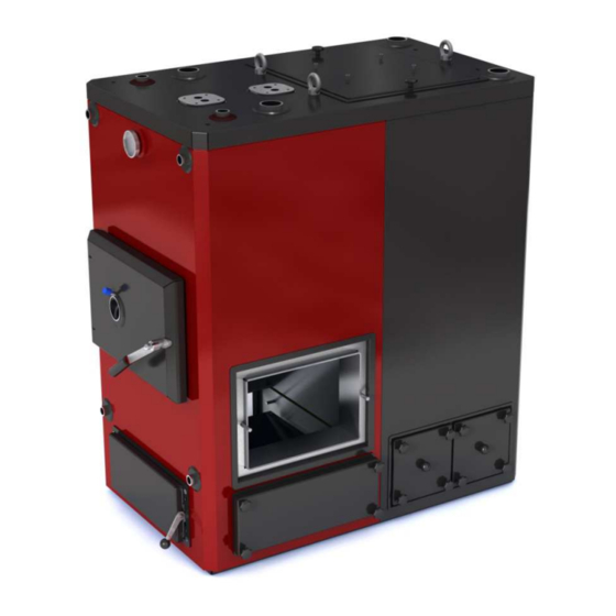

Summary of Contents for Ala-Talkkari Veto 30 kW
- Page 1 VSB20132803EN1.0 Veto Stoker Boilers 30, 60, 75, 80, 100, 120, 150, 220 kW User Manual Installation, Operation, and Service Retailer: Keep this manual.
-
Page 3: Table Of Contents
Contents Introduction ........................4 1.1. Contact information ....................4 1.2. Type plate information .................... 5 1.3. Warranty ......................... 6 1.3.1. Deficiencies in delivery and return of warranty parts ........7 1.3.2. Processing of warranty matters ................ 7 1.4. Product markings ....................8 1.5. - Page 4 7.2. Taking the boiler temporarily out of use ..............37 Emergency situations ....................38 8.1. Fire in the boiler room ................... 38 8.2. Chimney fire......................38 8.3. Boiler is overheating ..................... 38 8.4. Overpressure in the boiler ..................38 Service ......................... 40 9.1.
-
Page 5: Introduction
1. Introduction You have made a good choice in purchasing a Veto stoker boiler. The boiler together with a Veto burner offers a pure, economic, efficient, and near-emission-free way of burning renewable energy sources approved by the manufacturer. By avoiding using fossil fuels, you can considerably diminish the burden on the environment and prevent global warming. -
Page 6: Type Plate Information
1.2. Type plate information Write down the information from the type plate for easy reference. You need the information when, for example, ordering spare parts or claiming warranty. Figure 1 Type plate location Location of the type plate in all 30-220 kW boilers Table 1 Type plate information Model Manufacturing year... -
Page 7: Warranty
1.3. Warranty The manufacturer Veljekset Ala-Talkkari Oy grants a warranty for the products that it manufactures and markets. The user is liable for damage resulting from use of the equipment for any purpose other than that for which it was designed. -
Page 8: Deficiencies In Delivery And Return Of Warranty Parts
1.3.1. Deficiencies in delivery and return of warranty parts • Deficiencies in delivery must be reported within seven (7) days of the delivery. • Broken warranty parts must be returned to the plant for a warranty inspection (include a warranty report). •... -
Page 9: Product Markings
1.4. Product markings Pay attention to the warning and information stickers: they help you to avoid risks. Figure 2 Product marking locations... - Page 10 Table 2 Product markings on the device Item Product marking Hazardous voltage will cause Risk of carbon monoxide severe injury or death. poisoning and fire Turn off power. Wait 15 min Leaving covers or hatches open before service. Although control leads to immediate risk of fire unit is dead, supply voltage from when device is in operation.
- Page 11 Item Product marking Risk of carbon monoxide poisoning and fire Leaving covers or hatches open leads to immediate risk of fire when device is in operation. Close covers and hatches airtight.Ventilate properly before entering fuel bin. Always work in pairs. When entering fuel bin have a person outside fuel bin to secure your safety.
-
Page 12: Product Documentation
1.5. Product documentation Table 3 Related product documentation Manual name Identification Control unit A•T Log-1 and A•T Log-2 Control Unit User Manual ATL20132803EU1.0 Lambda 5S control unit 039 028 06_LAMBDA 5S GB_v8 Burners VetoMat User Manual VMB20132803EU1.0 Veto ChipMatic User Manual VCM20132803EU1.0 Veto 6 User Manual V6T20132803EU1.0... -
Page 13: Document Conventions
1.7. Document conventions 1.7.1. Symbols Table 5 Symbols used in this document Symbol Explanation Indicates a hazardous situation which, if not avoided, will result in death or serious injury. Indicates a hazardous situation which, if not avoided, could result in death or serious injury. Indicates a hazardous situation which, if not avoided, could result in minor or moderate injury. -
Page 15: General Safety And Warnings
General safety and warnings These general safety instructions help you to avoid dangerous situations when installing, operating or servicing the device. Important safety instructions are also presented in the beginning of each section. Do not make any alterations to the original device design. Any alterations to the product may result in serious hazard to people, property or environment. -
Page 17: Product Description
Product description Veto stoker boiler is an effective, economical, easy to use and environmentally friendly central heating boiler. Veto stoker boiler is designed to be used with a control unit and a stoker burner using solid fuel, such as chips, pellets and briquets as a heating source. The boiler delivery includes: •... -
Page 18: Optional Accessories
o If a particularly large amount of hot water is needed, it is possible to install two water coils side by side in the boiler. Available for 60, 80 and 100 kW boilers. • The burner can be installed to enter the boiler on the front, or from the right or the left side. -
Page 19: Technical Data
Technical data Table 7 Requirements for flues, chimney, compensation air holes, and chimney gas Height of the chimney 30 kW (from floor level) 60, 75, 80 kW 100 kW 120, 150 kW 220 kW 14 m Recommended chimney Ø 200 30, 60, 75, 80, 100 kW size Ø... - Page 20 Table 8 Technical data for boiler Power (using a solid fuel burner) Weight kg 1050 1650 Boiler 625x 725x 725x 725x 825x 825x 825x 1075x 1160x 1190x 1190x 1190x 1340x 1340x 1605x 1875x width x 1406 1425 1425 1620 1630 1630 1830 1850...
-
Page 21: Installation
Installation Installation of the device must only be performed by an authorized professional installer following all the requirements of the authority having jurisdiction over the installation. Incorrect installation of this boiler could result in severe personal injury, death, or substantial property damage from fire, carbon monoxide poisoning, soot or explosion. -
Page 22: Boiler Room Requirements
5.1. Boiler room requirements The boiler must be installed indoors. Clean the boiler room before bringing the boiler in. An unclean space is hazardous when moving the heavy boiler on its place. The minimum requirements for the boiler room are: •... -
Page 23: Chimney Requirements
• The size of the compensation air hole in the boiler room must be 1.5 x size of the chimney. • The connections to the water network and the radiator system must be available. • It is recommended that the boiler room is equipped with a water faucet and a drain made of cast iron. -
Page 24: Checking The Device
If a steel chimney is in use, it must be: • Acid-proof. • Isolated so that the temperature on the outer surface of the flue does not exceed 80°C. Risk of fire! Do not store anything on or near the chimney or the flue. -
Page 25: Boiler Connections
5.4. Boiler connections The boiler must be directly connected to the expansion tank and the relief valve. There should not be any valves between them. The figure shows the connections of a standard boiler. Figure 4 Boiler 30 kW Mixing valve connection 1½-inch output water connection and expansion connection 2-inch return water connection 1½-inch return water connection... - Page 26 Figure 5 Boiler 60-120 kW Mixing valve connection 2-inch return water connection 2-inch output water connection Drain valve connection ¾-inch discharging boiler connection Boiler temperature gauge and pressure gauge 1-inch feeding and expansion connection 2-inch electric resistance...
- Page 27 Figure 6 Boiler 150-220 kW ¾-inch thermostat connection 1-inch thermostat connection 1-inch feeding and expansion connection DN 65 connection, output water Drain valve connection 2-inch discharging boiler connection DN 65 connection, return water 2-inch output water connection The input side and output side of the mixing valve and water coil are marked on the boiler by colored signs (input side by a blue sign).
-
Page 28: Installing Venting
5.5. Installing venting Installation of the device must only be performed by an authorized professional installer following all the requirements of the authority having jurisdiction over the installation. Risk of fire and carbon monoxide poisoning! The chimney and the boiler must be connected airtight. Risk of fire! Overpressurized boiler causes backfire. -
Page 29: Connecting The Boiler Directly To The Heating Network
5.6.1. Connecting the boiler directly to the heating network The volume of the expansion tank(s) must be at least 5% of the total water content of the system (boiler water content + water network content). The figure is a sketch diagram; the connection between the boiler and the network varies from case to case. -
Page 30: Connecting The Boiler To The Heating Network Through Boiler Connections
A temperature gauge is installed in the output and return water pipe. The function of the boiler thermostat can be checked and adjusted by an output water gauge. 5.6.2. Connecting the boiler to the heating network through boiler connections The volume of the expansion tank(s) must be at least 5% of the total water content of the system (boiler water content + water network content). -
Page 31: Connecting The Boiler To A Water Accumulator
5.6.3. Connecting the boiler to a water accumulator The figure is a sketch diagram; the connection between the boiler and the network varies from case to case. Figure 9 Connection to a water accumulator Shut-off valve (shut off with a tool) Thermostatic mixing valve Thermostats Accumulator pump... - Page 32 The water accumulator is connected to the connector on top of the boiler. This means that the water in the hottest part of the boiler is conveyed to the water accumulator. The pipes between the boiler and the water accumulator (exit and return pipe, diameter DN 65) must be connected by a mixing valve, which regulates the heat of the water returning to the boiler to a temperature of 70ºC.
-
Page 33: Electrical Installation
5.7. Electrical installation During installation, always follow national, regional and local regulations, statutes, and installation instructions. Hazardous voltage! Only an authorized electrician shall perform electric installations. The connection diagram is delivered with the control unit. When installing an automatic controlling system (mixing valve) use the instructions provided by the supplier. -
Page 35: Commissioning
Commissioning Risk of explosion! Make sure that the boiler is full of water. If the boiler is not full of water and it is taken into use, the boiler thermostat does not register the water temperature, which can cause an explosion. Risk of carbon monoxide poisoning! There might come some smoke into the boiler room because the boiler water is cold and the chimney draft is poor. -
Page 36: Preparing The Heating Network For Use
• The flue gas flows freely. • All the doors of the boiler are closed. • The boiler is filled with water. • The safety devices are tested. • The shut-off valves between the water accumulator and the boiler are open. •... -
Page 37: Operation
Operation Incorrect operation of this boiler could result in severe personal injury, death, or substantial property damage from fire, carbon monoxide poisoning, soot or explosion. The boiler must only be used together with a Veto burner device and a control unit. Only burn solid, renewable fuels accepted by the manufacturer. -
Page 38: Heating With A Solid Fuel Burner
Figure 11 Boiler 150-220 kW Convection part lid Burner head connection Convection part service hatch Furnace ash box hatch Combustion chamber service door with an inspection opening Boiler temperature gauge and pressure gauge 7.1. Heating with a solid fuel burner For instructions, see the user manual of the burner and the control unit. -
Page 39: Emergency Situations
Emergency situations Adequate fire-fighting equipment must be available. The manufacturer recommends 2 x 6 kg dry chemical extinguishers near the boiler room. If they are stored inside the boiler room, they may be hard to reach in case of fire. 8.1. -
Page 41: Service
Service Service of the device must only be performed by an authorized professional following all the requirements of the authority having jurisdiction over the action. Risk of burn! Before servicing, turn the operating switch to the 0 position and turn off the main switch. Let the boiler cool down sufficiently. -
Page 42: Service Schedule
9.1. Service schedule Table 11 Service schedule Check the general boiler operation. Check the pressure. Check the temperature. Empty the ash box. Empty ash from the convection parts. Sweep the fire and convection parts. Check the condition of the gaskets. Sweep the flue. -
Page 43: Removing Ashes From The Boiler's Convection Parts
4. Clean the area underneath and around the ash box. 5. Return the ash box to its place. 9.4. Removing ashes from the boiler’s convection parts 1. Remove ashes from the upper parts of the convection parts. • Check and sweep the convection parts through the service doors on the top of the boiler. -
Page 44: Sweeping
9.5. Sweeping Always follow national, regional and local regulations for sweeping, and use professional services for sweeping the chimney even if the regulations do not require this. Ashes or fuel may contain constituents causing allergic reactions. • Use appropriate protective equipment such as respiration protector when handling ashes or fuel. -
Page 45: Sweeping The Chimney
9.5.2. Sweeping the chimney Always follow national, regional and local regulations for sweeping, and use professional services even if the regulations do not require this. Risk of fire! After sweeping, make sure that the service doors and the ash box are properly in place. Check and sweep the convection parts through the holes on top of the boiler. -
Page 46: Checking The Relief Valve
9.8. Checking the relief valve It is possible that the relief valve installed in the heating network gets stuck. This leads to excessive rise of the system pressure. Therefore, check the function of the relief valve 2–3 times a year. •... -
Page 47: Troubleshooting
10. Troubleshooting 10.1. Boiler water is boiling Possible cause Solution Faulty adjustment of the burner. Adjust the relation between the stand-by fire and the interpulse time or the settings of the overheating protector (changeable). The boiler thermostat is broken. Change the boiler thermostat. The fuel type has been changed, for Adjust the feeding values according to the example from chips to pellets. -
Page 48: System Does Not Produce Heat Even Though The Boiler Is Warm
10.3. System does not produce heat even though the boiler is warm Possible cause Solution There is not enough water in the Risk of explosion! Do not let boiler. cold water inside a hot boiler. It can cause an explosion. The water expands when overheated and the pressure rises in the boiler. -
Page 49: Smoky Flame
10.5. Smoky flame Possible cause Solution Faulty adjustment of burner or its fire Let the fire jet become warm or readjust. jet is cold. The moisture content of the fuel is too Change the fuel. high; no sufficient increase in the calorific value. -
Page 51: Device Components And Spare Parts
11. Device components and spare parts Figure 12 Veto 30 spare parts... - Page 52 Table 12 Veto 30 spare parts Name Item Knob 68536 47334 Wool cover 47318 Wool cover gasket 47327 Lifting eye nut M16 74801 Mixing valve 68540 Mixing valve gasket 68541 Pressure gauge and thermometer 68335 Ash box hatch 47325 Ash box hatch, ash screw 35003 Handle 34604...
- Page 53 Figure 13 Veto 60, 80, 100 spare parts 18 19...
- Page 54 Table 13 Veto 60, 80, 100 spare parts Name Item Mixing valve 68541 Mixing valve bottom gasket 68541 Knob 68536 Lid, 60/80 kW 36663 Lid, 100 kW 36680 Wool cover 47318 Wool cover 47936 Wool cover 47935 Ash box hatch, right 35025 Ash box hatch, left 35085...
- Page 55 Figure 14 Veto 75 and 120 spare parts...
- Page 56 Table 14 Veto 75 and 120 spare parts Name Item Knob 68536 Lid, 75 kW 36663 Lid, 120 kW 36680 Wool cover 47936 Wool cover 47935 Mixing valve 68541 Mixing valve bottom gasket 68541 Pressure gauge and thermometer 68335 Wool cover 48581 Lifting eye nut M16 74801...
- Page 57 Figure 15 Veto 150 spare parts...
- Page 58 Table 15 Veto 150 spare parts Name Item Wool cover 48148 Wool cover 48212 36706 Knob 68536 Ash box hatch 35424 Ash box hatch, blind 35951 Ash box hatch 36189 Wool cover 48505 Service door, right 35484 Service door, right 34600 Service door, left 34332...
- Page 59 Figure 16 Veto 220 spare parts...
- Page 60 Table 16 Veto 220 spare parts Name Item Wool cover 48260 35949 Wool cover 48261 35947 Knob 68536 Wool cover 48505 Ash box hatch 35424 Ash box hatch, blind 35951 Ash box hatch 36189 Wool cover 45776 Service door, right 35484 Service door, right 34600...
-
Page 61: Disposal Of The Boiler
12. Disposal of the boiler When used and serviced properly, the boiler will serve you for a long time. In time it will, however, become unprofitable to maintain and thereby be disposed of. The boiler device contains: • Electronic parts (sensors) •... -
Page 63: Glossary
13. Glossary Term Explanation Heating network The network where the heating water flows. Includes piping, radiators, valves, and a water accumulator. Heating system The heating system includes the heating network and also a boiler and a feeding device.
Need help?
Do you have a question about the Veto 30 kW and is the answer not in the manual?
Questions and answers