Advertisement
Quick Links
®
GENERAL INFORMATION
These passive infrared motion detectors are versatile wall-mounted units
employing Fresnel lenses and offering efficient protection patterns for
commercial and residential applications. Best coverage will be obtained if
mounting is selected such that the likely direction of intruder motion is
across the pattern.
When installed per the guidelines, the Split-Zone Optics technology in the
Aurora Series provides reasonable false alarm protection against pets and
other animals up to 40 lbs.
SPECIFICATIONS
Detection Method: Passive Infrared.
Coverage: Pet Immune Lens,
35 ft x 45 ft (10.6m x 13.7m), 90°.
Long Range Lens (optional, Part No. Aurora-LR),
75 ft x 10 ft (23m x 3m).
Detection Zones: Pet Immune Lens - 28 zones.
Long Range Lens - 6 zones,
(optional, Part No. Aurora-LR)
(8 over 8 long range, 8 intermediate, 4 short range).
Pulse Processing: Intermediate, Standard, or Harsh installer selectable.
Note: Use Standard for pet immune applications.
Temp. Compensation: Advanced dual-slope temperature compensation
adjusts for ambients both above and below body
temperature.
Detectable
Walk Rate: 0.5 - 10 ft/Sec (0.15 - 3m/Sec).
Mount Height: 7.0 ft recommended (2.1m).
Indicator: Red LED with enable/disable link.
Alarm Relay: Form A, SPST, 90mA@16VDC,
15-ohm protective resistor.
Input Voltage: 8 - 16VDC (Aurora and Aurora-T).
9-16VDC (Aurora-AT).
(Voltage reversal makes PIR inoperative)
Current:
Model Type
Aurora
Aurora-T
Aurora-AT
All currents nominal at 12VDC.
Standby: Power source should be capable of at least 4
hours of battery standby.
Tamper: Normally closed (with cover on), rated at 0.5A,
30VDC (Aurora-T/Aurora-AT only).
Operating Temp.: 14°F - 122°F (-10°C to +50°C).
Operating
Humidity: Up to 95% RH (max.), non-condensing.
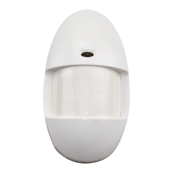
Dimensions: 2.9"W x 4.1"H x 1.5"D (max protrusion)
(60mm x 104mm x 38mm).
www.PDF-Zoo.com
INSTALLATION INSTRUCTIONS
w/LED, Alarm
w/o LED, Alarm
Standby
10mA
4mA
4mA
10mA
4mA
4mA
10mA
4mA
16mA
AURORA / AURORA-T / AURORA-AT
PASSIVE INFRARED MOTION DETECTORS
TOP VIEW
22.5'
0
22.5'
10'
20'
SIDE VIEW
7'
0
10'
20'
0
TOP VIEW
5
0
5
0
10
20
SIDE VIEW
10
5
0
10
20
0
Figure 1. Protection Patterns
for Installations Containing Pets
To take full advantage of the pet immunity in the Aurora Series, the guide-
lines below should be followed:
Mount the center of the detector 7 ft (2.1m) high.
Set the PIR sensitivity for Standard (STD).
Mount where animals cannot come within six feet of the detector by
climbing on furniture, boxes, or other objects.
Do not aim the detector at stairways that can be climbed by animals.
Note: This unit will provide immunity to false alarms for an individual
animal or a group of animals whose total weight is equal to or less than
40 pounds when the room temperature is above 50°F (10°C).
INSTALLATION
For optimal pet immunity performance, be sure to follow all the guidelines
described in the section "Special Instructions for Installations Containing
Pets."
A. Normal Surface Mounting
Mount the unit to a firm vertical surface. The wall wiring hole should be no
more than 5/16" (8mm) in diameter.
1. Remove the front cover as shown in Figure 2.
2. Refer to Figure 3. Knockout holes "A" in the base are for normal sur-
face mounting on a wall (remove PC board for full access to holes).
PET IMMUNE LENS
ALTERNATE COUNT POLARITY
EACH ZONE CONSISTS OF 2 FIELDS
30'
35'
30'
35'
LONG RANGE LENS
30
40
50
30
40
50
Special Instructions
K3119 8/99
60
70
75
60
70
75
Advertisement

Related Manuals for ADEMCO Aurora


Summary of Contents for ADEMCO Aurora
- Page 1 10mA 16mA All currents nominal at 12VDC. To take full advantage of the pet immunity in the Aurora Series, the guide- lines below should be followed: Standby: Power source should be capable of at least 4 hours of battery standby.
- Page 2 WIRING DETAILS in each of the four corners. 5. Replace front cover. TO TAMPER LOOP 12VDC POWER (AURORA-T/AURORA-AT ONLY) CONNECTS HERE (OBSERVE TO CLOSED CIRCUIT POLARITY) PROTECTIVE LOOP Figure 5.
- Page 3 (and proper voltage is supplied to the detector), return unit for cations. NOT recommended for use with the optional Long Range replacement. If present, check protective loop wiring. Lens (Aurora-LR). LED INOPERATIVE Harsh Pulse Processing (HARSH): This is the recommended setting for A.
- Page 4 Limited Warranty or otherwise if the detector is altered or improperly repaired or ser- viced by anyone other than Ademco factory service. In case of defect, return the detector to ADI or an autho- rized distributor for an immediate replacement.
Need help?
Do you have a question about the Aurora and is the answer not in the manual?
Questions and answers