Table of Contents
Advertisement
Advertisement
Table of Contents

Summary of Contents for Way Train 250S
- Page 1 METAL CUTTING BAND SAW MACHINE MODEL: 250S INSTRUCTION MANUAL 250S-060505-R2...
- Page 2 WARNING Some dust created by power sanding, sawing, grinding, drilling, and other construction activities contains chemicals known to the State of California to cause cancer, birth defects or other reprodrctive harm. Some examples of these chemical are: ‧Lead from lead-based paints. ‧Crystalline silica from bricks, cement and other masonry products.
-
Page 3: Table Of Contents
Table Of Contents Page No 1 Overall Aspect ………………………………………………………………… 2 2 Safety Rules For All Tools …………………………………………………… 3 3 Specification …………………………………………………………………… 6 4 Features ……………………………………………………………………..… 6 5 Transportation & Install ……………………………………………………… 7 6 Minimum Room Space For Machine Operation …………………………… 8 7 Make Proper Tooth Selection ……………………………………………….. -
Page 4: Overall Aspect
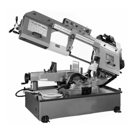
1.Overall Aspect Body Frame Change Speed Wheel Control Panel Tooth selection Vice Motor Cover Base Angle Sale... -
Page 5: Safety Rules For All Tools
WARNING: FAILURE TO FOLLOW THESE RULES MAY RESULT IN SERIOUS PERSONAL INJURY As with all machinery there are certain hazards involved with operation and use of the machine. Using the machine with respect and caution will considerably lessen the possibility of personal injury. However, if normal safety precautions are overlooked or ignored, personal injury to the operator may result. - Page 6 B. USE OF MACHINE: (1). REMOVE ADJUSTING KEYS AND WRENCHES. Form habit of checking to see that keys and adjusting wrenches are removed from tool before turning it "on". (2). DON'T FORCE TOOL. It will do the job better and be safer at the rate for which it was designed.
- Page 7 D. WORKING ENVIRONMENT: (1). KEEP WORK AREA CLEAN. Cluttered areas and benches invite accidents. (2). DON'T USE IN DANGEROUS ENVIRONMENT. Don't use power tools in damp or wet locations, or expose them to rain. Keep working area well-lighted. (3). KEEP CHILEREN AND VISITIORS AWAY. All children and visitors should be kept a safe distance from work area.
-
Page 8: Specification
G. NOISE: A weighted sound pressure level : 80 dB. H. SAFETY DEVICE: Interlock switch on cutting area as soon as the cover of cutting area is open, machine will stop at once witch the function of this switch. Do not remove this switch from machine for any reason, and check its function frequently. - Page 9 5.TRANSPORTATATION & INSTALLATION: 5-1.Unpacking 1. Transportation to desired location before unpacking, please use-lifting jack. (Fig. B) 2. Transportation after unpacking, please use heavy duty fiber belt to lift up the machine. Fig. B ALLWAYS KEEP PROPER FOOTING & BALANCE WHILE MOVING THIS MACHINE.
-
Page 10: Minimum Room Space For Machine Operation
5-3.Installation: (1) Always Keep proper footing & balance while moving this 430kgs machine. And only use heavy-duty fiber belt to lift the machine as per Fig. (A). (2) Hang the machine up, away from the floor, take away the 4 pads and assemble them on the auxiliary stand. -
Page 11: Make Proper Tooth Selection
7. MAKE PROPER TOOTH SELECTION For maximum cutting efficiency and lowest cost per cut, it is important to select the blade with the right number of teeth per inch (TPI) for the material being cut. The material size and shape dictate tooth selection. -
Page 12: Bi-Metal Speeds And Feeds
5.5 sq.ln. (35cm ) / 4" (100mm) distance =1.38(35mm) average width 1.38" (35mm), use a 4/6 Vari-Tooth NOTE: The band speed and cutting rate recommendations presented on this chart are approximations and are to be used as a starting point for most applications. - Page 13 A36(SHAPES),1040 1042,1541 1044,1045 1060 1095 Ni-Cr-Mo 8615,8620,8622 Alloy Steel 4340,E4340,8630 8640 E9310 Tool Steel A-10 H-11,H-12,H-13 Stainless Steel 410,502 440C 304,324 304L 316,316L TELLTALE CHIPS Chips are the best indicators of correct feed force. Monitor chip information and adjust feed accordingly. Thin or powdered chips –...
-
Page 14: Use Of Main Machine Parts
9.USE OF MAIN MACHINE PARTS 9-1.POWER SYSTEM AND CONTROL PANEL The electrical rating of your band saw is either with 230 volt-single phase,(or AC power volt-3 phase), magnetic control. Before connecting your machine to an electrical power system, be sure the motor shaft is running in the correct direction. - Page 15 distance is adjusted, tighten lock nut. 9-4.CHANGING SPEEDS AND ADJUSTING BELT TENSION If the belt (B) (Fig 6) is too loose, Loosen screw nut (A)(Fig5) adjust the screw to proper tension and lock the screw nut. The cutting speed is controlled by speed change C (Fig 6). Turn it clockwise to decrease the cutting speed and increase the cutting speed by turning counter-clockwise.
- Page 16 9-6.ADJUSTING CUTTING WIDTH First loosen clamp knob (A) (fig. 8). Move the left blade guide bar to the suitable position. Then tighten clamp knob (A). Fig.8 9-7.ADJUSTING BLADE GUIDE ROLLER BEARINGS, CARBIDE BLADE GUIDES AND BACK-UP BEARINGS Before making the following adjustments, make sure the blade is tracking and tensioned properly: 1.The back of the blade (A) (fig.
- Page 17 9-8.CLEARING THE CUTTTNG CHIP Please use steel brush to clear the chip on the blade teeth (fig 11) Fig.11 9-9.BLADE AND COOLING SYSTEM The use of proper cutting fluid is essential to obtain maximum efficiency from a band saw blade. The main cause of tooth failure is excessive heat build-up.
- Page 18 If an adjustment is necessary, proceed as follows: (fig. 13 and fig. 14) 1. Loosen clamp handle and set screw . Then turn hand-wheel A counterclockwise 1/2 turn. 2. Adjust the moveable vise jaw B to the suitable Position and put the work-piece Fig.14 3.Tighten clamp handle and set screw.
- Page 19 9-12.REMOVING AND INSTALLING THE BLADE Exchange of the saw blade: 1. Lift the saw arch to about the half height and close the lowering valve. 2. Turn the saw arch to the right. 3. Disconnect the machine from the power source.
- Page 20 9-14.GEAR BOX The gearbox should be drained and refilled after the first 50 hours of use and thereafter every 5 months, with Mobil Synthetic Gear Oil, SHC-636, ISO Viscosity Grade 680. This oil meets or exceeds American Gear Manufacturers Association (AG.M.A.) #8 compounded Cylinder Oil specifications.
-
Page 21: Maintaining
10.MAINTAINING That's easier to keep machine in good condition or best performance by means of maintaining it at any time than remedy it after it is out of order. (1) Daily Maintenance (by operator) (a) Fill the lubricant before starting machine everyday. (b) If the temperature of spindle caused over-heating or strange noise, stop machine immediately to cheek it for keeping accurate performance. - Page 22 4. Material too coarse 4. Use a blade of slow speed and small teeth spacing 5. Incorrect blade tension 5. Adjust to where blade just does not slip on wheel 6.Teeth in contact with material 6. Place blade in contact with before saw is started work after motor is starred...
- Page 23 4. Blade is too fine for work 4. Use coarse blade. 5. Gears aligned improperly 5. Adjust gears so that worm is in center of gear. 6. Gears need lubrication 6. Check oil path. 7. Cut is binding blade 7. Decrease reed anti speed Bad Cuts (Crooked) 1.
-
Page 24: Circuit Diagram
12. CIRCUIT DIAGRAM... - Page 25 (OP)
- Page 33 PARTS LIST MODEL NO. 250S CODE NO PART NO DESCRIPTION SPECIFICATION NOTE 105005GS Stand 105005G Stand 105005G-1 Stand Cover HW004 Washer HS527 M6x10L Cross Round Head Screw HN005 Hex. Nut 105003 Hanger Plate HW005 18*8.5-1.5 Washer HS243 M8x25L Hex. Head Screw...
- Page 34 PARTS LIST MODEL NO. 250S CODE NO PART NO DESCRIPTION SPECIFICATION NOTE 29-1 103125-7 ID1/2"x2.8tx320cm Net Tube 29-2 103125-5 ∮19 Hose Clamp 29-3 103125-6 ID1/2"x2.8tx126cm Net Tube 29-4 103125-8 Spray 29-5 103125-4 PT3/8"x1/2" Micro Control Block 29-6 103125-1 PT3/8"xPT3/8" Straight Connector...
- Page 35 PARTS LIST MODEL NO. 250S CODE NO PART NO DESCRIPTION SPECIFICATION NOTE HH001 ∮2x5L Rivet 101034 Degree-Meter 101029B Swivel Base(Upper) HS259 M10x25L Hex. Socket Head Screw HW006 Washer HW106 Spring Washer 103106 AN07 HW206 AW07 Washer 103046A Bracket 103088 Gap Ring...
- Page 36 PARTS LIST MODEL NO. 250S CODE NO PART NO DESCRIPTION SPECIFICATION NOTE 105089 Spring Cover HS227 M6x5L Hex. Socket Head Screw 105024 Switch Adjusting Bracket HS218 M5x10L Hex. Socket Head Screw 101012 Fixed Shaft HW106 Spring Washer HS261 M10x35L Hex. Socket Head Screw...
- Page 37 PARTS LIST MODEL NO. 250S CODE NO PART NO DESCRIPTION SPECIFICATION NOTE HS261 M10x35L Hex. Socket Head Screw HW018 26*10.5-3 Washer HN006 Hex. Nut HS262 M10x40L Hex. Socket Head Screw 101044 Vise Jaw Bracket(Rear) HW107 Spring Washer HS283 M12x45L Hex. Socket Head Screw...
- Page 38 PARTS LIST MODEL NO. 250S CODE NO PART NO DESCRIPTION SPECIFICATION NOTE 105208 Drive Wheel HS429 M8x5L Hex. Socker Headless Screw 105022 27x0.9x3353L-6/10T Blade HS258 M10x20L Hex. Socket Head Screw HW106 Spring Washer 19116S-1 Gear Box Assembly 105038 Splash Board HW004 14*6.5-1...
- Page 39 PARTS LIST MODEL NO. 250S CODE NO PART NO DESCRIPTION SPECIFICATION NOTE 105046 Cover For CE Only HS518 M5x5L Cross Round Head Screw For CE Only 105215 E=1/30 Speed Label 103115 Washer Ring 105079 Motor Bracket HW004 M6x20L Washer HS034 M6x20L Hex.
- Page 40 PARTS LIST MODEL NO. 250S CODE NO PART NO DESCRIPTION SPECIFICATION NOTE HS246 M8x40L Hex. Socket Head Screw HW105 Spring Washer 103259 HS519 M5x8L Cross Round Head Screw HW003 Washer 105210 Tension Indicating Plate HS231 M6x25L Hex. Socket Head Screw...
- Page 41 PARTS LIST MODEL NO. 250S CODE NO PART NO DESCRIPTION SPECIFICATION NOTE 103127-4 ID1/4"x2.2tx64cm 556-6 Net Tube CA609ZZ 609ZZ Bearing 103026 Bearing Pin HS434 M8x30L Hex. Head Screw HN005 Hex. Nut HW005 Washer HS242 M8X20L Hex. Socket Head Screw HS426 M6x30L Hex.
- Page 42 PARTS LIST MODEL NO. 250S CODE NO PART NO DESCRIPTION SPECIFICATION NOTE HN006 Hex. Nut 103049 Blade Guard (Rear) 103032 Arm (Right) HS433 M8x25L Hex. Socker Headless Screw HN005 Hex. Nut 1050209 Tooth Selection Paster HS241 M8x15L Hex. Socket Head Screw...
- Page 43 MANUFACTURER: ADDRESS: SERIAL No.: PLEASE WRITE DOWN THE SERIAL NO. ON THIS BLOCK FROM THE NAME PLATE AFTER YOU RECEIVE THIS MACHINE.
Need help?
Do you have a question about the 250S and is the answer not in the manual?
Questions and answers