Advertisement
High Density
Thermocouple Input
Module
Product Specifications
and Installation Data
1
DESCRIPTION
The Horner APG High Density Thermocouple Input Module offers superior channel density, with 16 input
channels per module. This module allows thermocouple temperature sensors to be directly connected to
the PLC without external signal processing (transducers, transmitters, etc.).
All analog and digital
processing of the thermocouple signal is performed on the module. Temperature resolution is 0.5°C, and
temperature values may be reported to the PLC %AI I/O table in 0.5°C or 0.5°F increments. This module
features open circuit detection, where the %AI register goes to its maximum value upon an open circuit
condition, and a corresponding %I bit is energized. Field wiring is connected to a special high density, 32
position removable terminal block. Recommended wire size is 24 AWG.
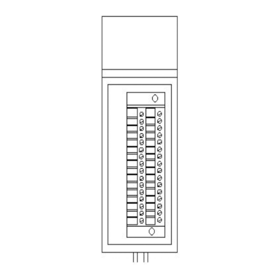
16 CHANNEL
THERMOCUPLE
HE693THM166 S/N: 1965
Horner APG, LLC.
Figure 1 – HE693THM166 (Front View)
Figure 2 – HE693THM166 (Right Side View)
06 December 2004
MAN0090-05
Advertisement
Table of Contents

Summary of Contents for HORNER HE693THM166
-
Page 1: Product Specifications
Installation Data DESCRIPTION The Horner APG High Density Thermocouple Input Module offers superior channel density, with 16 input channels per module. This module allows thermocouple temperature sensors to be directly connected to the PLC without external signal processing (transducers, transmitters, etc.). -
Page 2: Specifications
PAGE 2 06 December 2004 MAN0090-05 SPECIFICATIONS Table 1 – HE693THM166 Specification THM166 Specification THM166 I/O Points Power Consumption 100mA @ 5VDC 16 %AI, 16 %I Required Number of Channels Input Impedance 20Mohms Maximum Safe Types Supported J, K, N, T, E, R, S, B, C, X... - Page 3 MAN0090-05 06 December 2004 PAGE 3 Table 2 – Configuration Parameters Byte Size Size 00: J 03: T 06: S 0:0.5°C (see 01: K 04: E 07: B chart) 1:0.5°F 08: C 02: N 05: R 09: X Byte 2 sets digital filtering, Byte 3 sets temperature units, and Byte 5 sets the thermocouple type. 2 0 0 0 4 0 0 0 6 0 0 0...
-
Page 4: Installation And Safety
PAGE 4 06 December 2004 MAN0090-05 WIRING INSTALLATION AND SAFETY Special care must be taken with grounded junction sensors to avoid applying a voltage potential to the thermocouple junction. Extension wire of the proper Thermocouple type must be used. Keep total wire resistance less than 100Ω... -
Page 5: Technical Assistance
Before each use, inspect all cables for breaks or cracks in the insulation. Replace immediately if defective. TECHNICAL ASSISTANCE For manual updates and assistance, contact Technical Support at the following locations: North America: (317) 916-4274 www.heapg.com email: techsppt@heapg.com Europe: (+) 353-21-4321-266 www.horner-apg.com... - Page 6 PAGE 6 06 December 2004 MAN0090-05 NOTES...
Need help?
Do you have a question about the HE693THM166 and is the answer not in the manual?
Questions and answers