Table of Contents
Advertisement
575 Birch Street, Forestville, CT 06010
Phone (866) 322-1237 Fax (866) 322-1233
WWW. LOCKNETICS .COM
390DEL
DELAYED EGRESS
MAGNETIC LOCKING SYSTEM
General Description............................................. 2
Technical Specifications....................................... 2
Pre Installation Considerations............................ 3
Mechanical Installation.........................................4
Template Information............................................4
Wiring Information/Board Layout......................... 8
Terminal Layout/Dipswitch Settings..................... 9
100CAB/TR80/TR81 Hook-up..............................9
390-2 (Double Unit) Wiring Information.............. 10
Monitoring/Control Wiring and Examples.............11
Programming - General Information.................... 12
Code/iButton Functions........................................12
Keypad Initialization............................................. 13
"System 7" iButton Programming.........................13
PLEASE READ ALL INSTRUCTIONS PRIOR TO INSTALLING THE ELECTROMAGNETIC LOCK.
IMPORTANT! This manual is intended to be kept for programming, maintenance,
and trouble shooting purposes. Do not dispose of after installation. Please present
this manual to facility manager upon completion of installation.
Form 39990 Rev. E
INSTALLATION AND PROGRAMMING
HANDLE THE EQUIPMENT CAREFULLY
ELECTROMAGNET OR THE ARMATURE MAY REDUCE LOCKING EFFICIENCY
MAGNETIC LOCKING SYSTEM
Erasing Memory................................................... 13
Time Delay Settings............................................. 14
Automatic Relock Time Delay.............................. 14
Nuisance Alert Time Delay...................................14
Door Propped Open Alarm (SEC)....................... 14
Anti Tamper Switch Information........................... 15
Keypad Manual Programming............................. 16
iButton Manual Programming.............................. 18
TEP1 Initialization................................................ 18
Maintenance.........................................................21
Trouble Codes......................................................21
Error Codes..........................................................21
Overall Dimensions.............................................. 22
,
DAMAGING THE MATING SURFACES OF THE
1
390/390-2 DEL
.
09/23/2005
Advertisement
Table of Contents

Summary of Contents for Locknetics 390DEL
-
Page 1: Table Of Contents
390/390-2 DEL MAGNETIC LOCKING SYSTEM INSTALLATION AND PROGRAMMING 575 Birch Street, Forestville, CT 06010 Phone (866) 322-1237 Fax (866) 322-1233 WWW. LOCKNETICS .COM 390DEL DELAYED EGRESS MAGNETIC LOCKING SYSTEM General Description..........2 Erasing Memory........... 13 Technical Specifications........2 Time Delay Settings..........14 Pre Installation Considerations...... -
Page 2: General Description
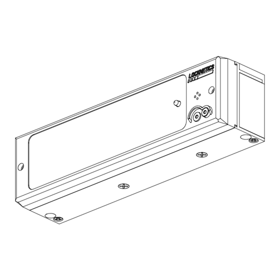
390 DEL and 390-2 DEL series magnetic locks described in this manual share the same access con- trol circuitry. With optional access control input devices (Locknetics keypads or iButton readers) the locks can hold up to 150 codes or iButtons standard for access, toggle, lockout, or special functions. Dry contact inputs allow for fire alarm tie in and remote release/reset capabilities. -
Page 3: Pre Installation Considerations
SELF TAPPING SCREWS Armature mounting hardware is for door thickness of 1-3/4 inches. For doors thicker than 1-3/4” consult your Locknetics distributor for availability FOR SEX NUTS FOR USE ON of sex nuts. 1-3/4” DOORS OTHER THAN CONSULT DISTRIBUTOR DELAYED EGRESS LOCKS: Local codes generally require the signage, provided with the product, to be posted on or near the door. -
Page 4: Mechanical Installation
390/390-2 DEL MAGNETIC LOCKING SYSTEM INSTALLATION PROCEDURE 1. PREP DOOR AND FRAME: The paper template is the preferable way to prepare the door and frame. If for any reason it is not available, use the dimensions shown below to mark the centerlines of the holes. Note that the layout is not symmetrical with respect to the centerline of the armature. - Page 5 390/390-2 DEL MAGNETIC LOCKING SYSTEM 2. MOUNT ARMATURE TO DOOR Assemble using hardware provided in the order shown. All hardware shown must be used except where noted. Note that the tapered washer must be placed with the pointed side facing away from the door and toward the armature.
- Page 6 390/390-2 DEL MAGNETIC LOCKING SYSTEM 4. TEMPORARILY MOUNT TEMPLATE OR MAGNET TO MOUNTING PLATE Using 1/4-20 flat head screws, temporarily secure the plastic or metal template to the mounting plate, carefully passing the wiring through the hole in the template. Make sure that the hole in the template lines up with the socket cap...
- Page 7 390/390-2 DEL MAGNETIC LOCKING SYSTEM 6. SECURE MOUNTING PLATE Using the Mounting Plate as a template, drill the four remaining mounting holes. Tighten two 10-24 self tapping pan head screws If using #10 self-tapping, flat-head screws drill 5/32" dia. holes and drive four screws tight. If using #10-24 flat head machine screws, drill and tap for #10-24 threads and tighten four screws.
-
Page 8: Wiring Information/Board Layout
390/390-2 DEL MAGNETIC LOCKING SYSTEM 8. MAKE WIRING CONNECTIONS AND SET DIPSWITCHES Connect wiring to main terminal strip. If furnished, connect DSM1 and DSM2 to board as shown. Note that if the unit has only the DSM option, connect the plug into the DSM1 jack. If the unit has only the SEC and/or BOCA option, con- nect the plug into the DSM2 jack. -
Page 9: Terminal Layout/Dipswitch Settings
390/390-2 DEL MAGNETIC LOCKING SYSTEM TERMINAL LAYOUT TB1: RELEASE RESET POWER INPUT FIRE ALARM AUXILIARY NC NO INPUT INPUT INPUT INPUT ALARM DSM OUTPUT MBS OUTPUT DRY CONTACT 12/24 VOLTS OUTPUT (OPTIONAL) (OPTIONAL) AC OR DC APPLY A (SEE CLOSURE (STANDARD) CONTACTS CHANGE CONTACTS CHANGE... -
Page 10: 390-2 (Double Unit) Wiring Information
390/390-2 DEL MAGNETIC LOCKING SYSTEM 390-2 (DOUBLE UNIT) INSTALLATION WIRING BETWEEN TO POWER UNITS AND WIRING INFORMATION SUPPLY MONITORING The electronic 390 series has the capability of STATION WIRE ACCESS COVERS operating two locks with the “brain” of one. The lock with the central processing unit is referred to as the “master”... -
Page 11: Monitoring/Control Wiring And Examples
390/390-2 DEL MAGNETIC LOCKING SYSTEM MONITORING AND CONTROL SYSTEM WIRING INFORMATION AND EXAMPLES Shown below are basic wiring examples for supplying power, monitoring lock, door and alarm status as well as fire alarm, auxiliary, release/reset and timer inputs. Note that most national codes require that magnetic locks become unlocked whenever a fire alarm condition exists. -
Page 12: Programming: General Information
The exception to this is “System 7” programming in which up to 7 iButtons can be added. With System 7 program- ming, the unit must have or be attached to an iButton reader, or a Locknetics keypad that has an iButton reader. The iButtons can be entered into the reader on the cover (See page 13). -
Page 13: Keypad Initialization
This procedure will allow up to seven iButtons to be programmed into a lock equipped with an iButton reader or Locknetics keypad with an iButton reader. iButtons will be of the Normal Access type and will unlock the unit for the relock time delay. -
Page 14: Time Delay Settings
390/390-2 DEL MAGNETIC LOCKING SYSTEM SETTING TIME DELAYS MANUALLY: AUTOMATIC RELOCK DELAY (factory default: 8 seconds) The amount of time the lock is de-energized after release. Programmable 1-30 seconds. A. Set SW4 dipswitch #6 to OFF (if it is on). B. -
Page 15: Anti Tamper Switch Information
390/390-2 DEL MAGNETIC LOCKING SYSTEM ANTI TAMPER SWITCH - IMPORTANT NOTE: ANTI TAMPER The electronic 390 models come standard with the ATS SWITCH (Anti Tamper Switch). When the cover is removed, the TERMINALS alarm will sound. It can be reset either by momentarily 17&18 shorting terminals 17 and 18, which is the reset input, or by entering a valid keypad code or iButton. -
Page 16: Keypad Manual Programming
MAGNETIC LOCKING SYSTEM MANUAL PROGRAMMING - KEYPAD When using a keypad to manually program a 390DEL, the keypad must first be initialized. It is a recommended that the factory default Master Code be changed. Doing so will delete all factory default codes and ensure the security of the system. - Page 17 390/390-2 DEL MAGNETIC LOCKING SYSTEM TO ADD FUNCTION CODES (Note that a three digit function code sets the function of the user code) UP TO 150 NEW CODES CAN BE ADDED BY RETURNING HERE. Master Code *...33*...111*...New Access Code (3-8 digits) * ...* (to end) 191*...New Toggle Code 115*...New Lockout Code...
-
Page 18: Ibutton Manual Programming
390/390-2 DEL MAGNETIC LOCKING SYSTEM MANUAL PROGRAMMING - iButtons When manually programming the 390-2 DEL for iButtons, a TEP1 programmer must first be initialized. Only one pro- grammer can be initialized to a particular lock. A Master iButton must also be initialized at the same time as the pro- grammer and will be used to enter the programming mode. - Page 19 390/390-2 DEL MAGNETIC LOCKING SYSTEM TO ADD FUNCTION iButtons (Note that a three digit function code sets the function of the user iButton) UP TO 150 NEW iButtons CAN BE ADDED BY RETURNING HERE. Master iButton ...33*...111*...New PIN(3-8 digits)*...New Access iButton ...* (to end) 191*...New Toggle iButton 115*...New Lockout iButton 113*...New One-Time Access iButton...
- Page 20 390/390-2 DEL MAGNETIC LOCKING SYSTEM The table below is intended to provide all possible indications and states which can be encoun- tered under normal operation. Note that some conditions or features are only available on certain models or when certain options are included. Form 39990 Rev.
-
Page 21: Maintenance
390/390-2 DEL MAGNETIC LOCKING SYSTEM ERROR CODES: If an error is made while manually programming a lock, an error code indication will be indicated at the iButton reader or keypad. The LED(s) will flash several times. Count the number of flashes and refer to the chart below for diagnosis. ERROR CODES NUMBER OF ERROR... -
Page 22: Overall Dimensions
390/390-2 DEL MAGNETIC LOCKING SYSTEM Form 39990 Rev. E 09/23/2005...
Need help?
Do you have a question about the 390DEL and is the answer not in the manual?
Questions and answers
I’m pushing sw-2 and it’s flashing green and I need it to flash yellow to program propped door alarm
To change the Locknetics 390DEL from flashing green to flashing yellow to program the propped door alarm:
1. Set SW4-6 to ON (if it is off).
2. Press and release SW2. The LED will begin flashing YELLOW.
This indicates that the lock is in programming mode for the propped door alarm.
This answer is automatically generated