Table of Contents
Advertisement
Advertisement
Table of Contents

Summary of Contents for Samyung SGN-500
- Page 1 User Manual...
- Page 2 User manual...
- Page 3 Problem caused by overheating does not recover even after the temperature has gone down. If you need technical assistance, please visit our SAMYUNG ENC office or our website www.samyungenc.com. User Manual...
- Page 4 User manual...
-
Page 5: Table Of Contents
1 Overview 1-1 Outline ..................... 6 1-2 Characteristics.................... 7 1-3 Specifications .................... 8 1-5 Components ....................9 1-6 Option Components ................... 9 2 Installation 2-1 Unpacking and check ................10 2-2 Selecting where to install ................10 2-3 Connecting the power supply ..............11 2-4 Connecting the external data .............. -
Page 6: Overview
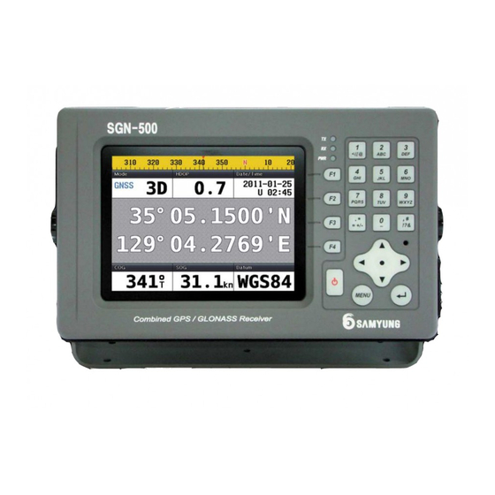
1 Overview 1-1 Outline Thank you for purchasing our product SGN-500. Before using the product, please read carefully over this manual so that the product functions fully for its intention, and also keep this manual in a safe place after reading this. The information of circuit on the software and hardware of this product is only owned by our company. -
Page 7: Characteristics
1-2 Characteristics 1. Meets the IMO and MSC international standard. 2. Meets the standard of national Wireless Telegraphy Act (WTA) and its law. 3. The range of voltage use is wide and it is easy to install with its small size. 4. -
Page 8: Specifications
1-3 Specifications [SGN-500] General Specifications Details Size 150 mm(W) x 242 mm(H) x 61 mm(D) 5.6 inch, TFT color, 640 x 480 pixel Voltage 10 ~ 36 V DC Current 400 mA - Minimum brightness of LCD 560 mA - Maximum brightness of LCD Operation temperature -15°... -
Page 9: Components
1-5 Components Contents Part number Display SGN-500-R Bracket SGN-500-DB Power cable CVV SB 0.75 SQMM x 2C(3Meter) Bracket mounting bolt SGN-500-BP GLONASS antenna GLONASS-50 GLONASS antenna holder User manual in English SGN-500-ME 25P data connector HDBB25S 1-6 Option Component model... -
Page 10: Installation
2 Installation 2-1 Unpacking and check When unpacking the products, you must match with the components with what you have ordered and handle them carefully. Especially you must check if the equipment has been damaged while being transported. If you discover any damage, you must manage it before installing it. -
Page 11: Connecting The Power Supply
2-3 Connecting the power supply 1. 3P connector located at the back of the equipment is the power supply, and number 1 is (+) and 3 is (-). You may connect the DC power between 10V-36V to it. 2. Connect the 3P plug which fits the connecter for power supply to the 3P cable, and be aware of the (+) and (-) when connecting. -
Page 12: Installing Antenna
2-5 Installing antenna GNSS Antenna’s function gets highly affected by where it is installed at. Therefore avoid any obstacles around it, and keep 1m distance between other antennas. You must waterproof the parts that are exposed to the outside. 1. You must turn OFF the equipment when connecting antenna. Press the KEY for 2 seconds to shut down. -
Page 13: Installing Dgnss
2-6 Installing DGNSS DGNSS antenna must be installed when using DGNSS. 1. DGNSS antenna: Refer to the “2-5 Installing antenna” when installing. *. The DGNSS antenna of main unit’s connector is as below. Number Pin name function POWER+ positive Power input 12V DC 1,13,14,25 POWER- Negative(There is no need to connect all the pins. -
Page 14: Connection To Equipment Cable
2-7 Connection to equipment cable Please refer to the external connection diagram for connection between mutual equipment, to install it at the most convenient place. 1. When wiring the power, if it is DC wire, you must use the CABLE supplied by us or CABLE with enough capacity of current. - Page 15 STANDARD GNSS ANTENNA Option Buffer Option Option Power supply(SP5AD) Beacon Receiver Input-AC110,220V DC24V Output-DC24V External Device User Manual...
-
Page 16: Function
3 Function 3-1 Position Description of Display Position displays when you press F1. It displays the current position in latitude and longitude. ③ ① ② ⑦ ⑧ ⑤ ⑥ ④ ①Mode GLONASS Receiving status: (" "/“DR”/“2D”/“3D”/"WAAS"/"DGLONASS"/"GLONASS"/“SIM") “3D” on the top left changes to “DR” when satellite has not been selected, and when satellite has been selected and positioning is 2 dimensional, it will display “2D”, and 3D when it is 3 dimensional. - Page 17 * “WAAS” gets displayed when WASS signal is received. ②HDOP(Horizontal Dilution of Precision) This shows the precision of the horizontal direction (longitude and latitude). The less value means less error. ③Date/Time Date represents the present Year, Month and date Time represents the time in 24 hours (10:07) UTC Time is displayed as “U”, and “L’”...
-
Page 18: High Way
3-2 High Way Press F2 to display High Way High way shows in 3D when vessel is sailing to the destination. ① TRIP ① It shows the distance travelled after the equipment has been turned on. 3-3 DATA DATA displays when you press F3 It shows COG and SOG of vessel in gauge User manual... -
Page 19: Satellite Information
3-4 Satellite Information Satellite information displays when you press F4. Equipment needs some time to receive GNSS signal when first turned on. Satellite information displays GNSS gain and GNSS location as below. ① ② ① ③ ④ ① ① ① Location of GNSS satellite ②... -
Page 20: Menu
4 Menu W When this key is pressed, MENU displays 4-1 Setup Output Data By using NMEA0183, you may select the data to transmit when you are communicating with other equipment. Select which data you wish to transmit and press SAVE. ①... - Page 21 ①GBS GNSS Satellite Fault Detection 5 6 7 $--GBS,hhmmss.ss,x.x,x.x,x.x,xx,x.x,x.x,x.x*hh 1) UTC time of the GGA or GNS fix associated with this sentence 2) Expected Error in latitude 3) Expected Error in longitude 4) Expected Error in altitude 5) ID number of most likely failed satellite 6) Probability of missed detection for most likely failed satellite 7) Estimate of bias in meters on most likely failed satellite 8) Standard deviation of bias estimate...
- Page 22 ④VTG Course Over Ground and Ground Speed | | | | | | | $--VTG,x.x,T,x.x,M,x.x,N,x.x,K,a*hh 1) Coures over ground, degrees True 2) Coures over ground, degrees Magnetic 3) Speed over ground, Knots 4) Speed over ground, Km/hr 5) Mode Indicator ⑤GGA Global Positioning System Fix Data $--GGA,hhmmss.ss,llll.ll,a,yyyyy,.yy,a,x,xx,x.x,x.x,M,x.x,M,x.x,xxxx*hh...
- Page 23 ⑦DTM DTM Datum Reference $--DTM,ccc,a,x.x,a,x.x,a,x.x,ccc*hh 1) Local datum code - WGS84=W84, WGS72=W72, SGS85=S85, PE90=P90, User defined=999, IHO datum code 2) Local datum subdivision code 3) Lat offset, minutes, N/S 4) Lon offset, minutes, E/W 5) Altitude offset, meters 6) Reference datum code – WGS84=W84, WGS72=W72, SGS85=S85, PE90=P90 User Manual...
-
Page 24: Setup I/O Port
4-2 SETUP I/O PORT Set the speed same with the equipment you are communicating with. Set the speed then press SAVE. 4-3 PORT MONITORING The details of transmission gets displayed ① ② ③ ① User manual... -
Page 25: Configuration
① When you press GNSS Button (F1), NMEA0183 data gets displayed which is created from the internal GNSS module. ②It displays the data received from the external data port when you press EXT (F2). ③ When you press STOP (F3), screen freezes, and it will only display the details received until then. - Page 26 User manual...
-
Page 27: Diagram
5 Diagram 5-1 External diagram User Manual... -
Page 28: Glonass Antenna Diagram
5-2 GLONASS antenna diagram User manual... - Page 29 User Manual...
- Page 30 The repair can be done at SAMYUNG ENC or our agencies. When you require service, please send the product to SAMYUNG ENC’s A/S center or the official agency. We will repair them for you.
- Page 31 User Manual...
- Page 32 User manual...
- Page 33 User Manual...
Need help?
Do you have a question about the SGN-500 and is the answer not in the manual?
Questions and answers