Table of Contents
Advertisement
Quick Links
View our inventory
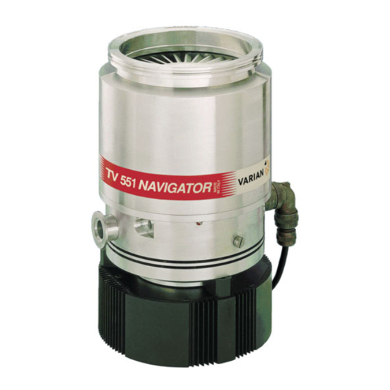
TV 551/701
Navigator
969-8832
969-8834
969-8836
969-8922
969-8924
969-8926
969-8974
87-900-934-01(D)
SEPTEMBER 2003
969-8833
969-8835
969-8837
969-8923
969-8925
969-8927
969-8975
MANUALE DI ISTRUZIONI
BEDIENUNGSHANDBUCH
NOTICE DE MODE D'EMPLOI
MANUAL DE INSTRUCCIONES
MANUAL DE INSTRUÇÕES
BEDRIJFSHANDLEIDING
INSTRUKSTIONSBOG
BRUKSANVISNING
INSTRUKSJON MANUAL
OHJEKÄSIKIRJA
ODHGIES CRHSEWS
INSTRUCTION MANUAL
Advertisement
Table of Contents

Subscribe to Our Youtube Channel
Related Manuals for Varian TV 551

Summary of Contents for Varian TV 551
- Page 1 View our inventory MANUALE DI ISTRUZIONI TV 551/701 BEDIENUNGSHANDBUCH Navigator NOTICE DE MODE D’EMPLOI MANUAL DE INSTRUCCIONES 969-8832 969-8833 MANUAL DE INSTRUÇÕES 969-8834 969-8835 BEDRIJFSHANDLEIDING 969-8836 969-8837 969-8922 969-8923 INSTRUKSTIONSBOG 969-8924 969-8925 BRUKSANVISNING 969-8926 969-8927 INSTRUKSJON MANUAL 969-8974 969-8975 OHJEKÄSIKIRJA...
- Page 2 TV 551 Navigator TV 701 Navigator...
-
Page 5: Table Of Contents
BRUGSANVISNING ............................13 BRUKSANVISNING............................15 BRUKERVEILEDNING .............................17 KÄYTTÖOHJEET .............................19 PDHGIES CRHSEWS ............................21 INSTRUCTIONS FOR USE..........................23 TECHNICAL INFORMATION ...........................25 DESCRIPTION OF THE TV 551/701 NAVIGATOR ..............25 Pump Description ......................26 Controller Description ......................26 TECHNICAL SPECIFICATION ....................27 TV 551/701 NAVIGATOR OUTLINE....................28 INTERCONNECTIONS........................31 P3 - Vent ..........................31 P4 –... -
Page 6: Istruzioni Per L'uso
Durante l'operazione di disimballaggio, prestare partico- lare attenzione a non lasciar cadere il TV 551/701 Navigator e a non sottoporlo ad urti o vibrazioni. Non disperdere l'imballo nel- l'ambiente. Il materiale è completamente riciclabile e risponde alla direttiva CEE 85/399 per la tutela dell'ambiente. - Page 7 “RS 232/485 COMMUNICATION DESCRIPTION” chnical Information". nell’appendice “Technical Information”). Il LED verde posto sul pannello della base del TV 551/701 Na- Il TV 551/701 Navigator può essere installato in qualsiasi posi- vigator indica, con la frequenza del suo lampeggio, le condizio- zione.
-
Page 8: Gebrauchsanleitung
ALLGEMEINE INFORMATIONEN VOR DER INSTALLATION Dieser Apparat ist für den fachmännischen Gebrauch bestimmt. Modell TV 551/701 Navigator wird in einer speziellen Schutzver- Vor dem Gebrauch hat der Benutzer dieses Handbuch sowie packung geliefert. Eventuelle Transportschäden sind der zustän- alle weiteren mitgelieferten Zusatzdokumentationen genau zu digen örtlichen Verkaufsstelle zu melden. - Page 9 Der ISO-K-Flansch kann zum Beispiel mit hochfesten Stahlklem- men befestigt werden (Typ Modell Varian IC 63250 DCMZ). Die Zur Einschaltung von Modell TV 551/701 ist es mit der erforder- nachstehende Tabelle gibt an, wie viele Klemmen IC 63250 lichen Versorgungsspannung zu versorgen. Der eingebaute DCMZ für jeden Flansch erforderlich sind und mit welchem...
-
Page 10: Mode D'emploi
Navigator est totalement exempt d'agents polluants et il est par conséquent indiqué pour toutes les applications exigeant un vide "propre". Le TV 551/701 Navigator est en outre doté de connecteurs auxiliaires permettant d'alimenter un ventilateur supplémentaire, de commander la soupape de ventilation, de le piloter à... - Page 11 Lorsque la pompe est utilisée pour le pompage de gaz toxiques, inflammables ou radioactifs, suivre les procédures Fixer le TV 551/701 Navigator de façon stable en assurant la typiques de chaque gaz. collerette d'entrée de la turbopompe à la contre-collerette du Ne pas utiliser la pompe en présence de gaz explosifs.
-
Page 12: Instrucciones De Uso
INSTRUCCIONES DE USO Durante la operación de desembalaje, tener cuidado de que no INFORMACIÓN GENERAL se caiga el TV 551/701 Navigator y de no someterlo a golpes o Este equipo es para uso profesional. El usuario ha de leer vibraciones. - Page 13 Fijar el TV 551/701 Navigator en posición estable, montando la apropiados típicos de cada gas.No usar la bomba cuando haya brida de entrada de la turbo-bomba en la contrabrida del gases explosivos. sistema, con conexión capaz de resistir a un par de 8600 Nm en torno a su propio eje.
-
Page 14: Instruções Para O Uso
Para ulteriores poderiam ter ocorrido durante o transporte, entrar em contacto detalhes, consultar o apêndice "Technical Information". com o escritório de vendas local. O TV 551/701 Navigator deve ser ligado a uma bomba primária (consultar esquema em "Technical Information"). 87-900-934-01(D) - Page 15 Navigator de alta resistência (como o modelo Varian IC 63250 DCMZ). Para ligar o TV 551/701 é suficiente fornecer a tensão de A tabela a seguir contém, por cada flange, o número de bornes alimentação. O controller incorporado reconhece automaticamente IC 63250 DCMZ necessários e o respectivo torque de aperto.
-
Page 16: Gebruiksaanwijzingen
De TV 551/701 Navigator moet op een primaire pomp Zorg er bij het uitpakken voor dat de TV 551/701 Navigator niet aangesloten zijn (zie schema in "Technical information"). kan vallen en geen stoten of trillingen te verduren krijgt. - Page 17 Bevestig de TV 551/701 Navigator in een stabiele positie door procedures worden gevolgd die speciaal voor elk type gas zijn de inlaatflens van de turbopomp op de contraflens van het opgesteld. Gebruik de pomp niet in aanwezigheid van systeem te monteren, met een verbinding die in staat is om een explosieve gassen.
-
Page 18: Brugsanvisning
BRUGSANVISNING Sørg for, at TV 551/701 Navigator ikke tabes eller udsættes for GENEREL INFORMATION stød ved udpakningen. Dette udstyr er beregnet til professionel anvendelse. Brugeren Smid ikke emballagen ud. Materialet kan genbruges 100% og bør læse denne brugsanvisning anden yderligere opfylder EU-direktiv 85/399 om miljøbeskyttelse. - Page 19 Forbindelsen skal kunne tåle et drejemoment på Start og anvendelse af TV 551/701 Navigator 8.600 Nm omkring dens egen akse. For at starte TV 551/701 er det tilstrækkeligt at tilslutte et ISO-K-flangen kan eksempelvis fastspændes ved hjælp af forsyningsstik.
-
Page 20: Bruksanvisning
Komponenter som skall utsättas för vakuum får inte hanteras dokumentation från Varian före användning av utrustningen. med bara händer p g a kontamineringsrisken. Använd alltid Varian tar inget ansvar för skador helt eller delvis till följd av handskar eller liknande skydd. åsidosättande av instruktionerna, olämplig användning av person utan tillräcklig kunskap, obehörigt bruk av utrustningen... - Page 21 ädelgas (kväve eller argon) för att skydda lagren (se bilagan “Technical information”). Fäst TV 551/701 Navigator i ett stabilt läge genom att ansluta turbopumpens intagsfläns till systemets fläns som måste tåla ett vridmoment på 8600 Nm kring sin axel.
-
Page 22: Brukerveiledning
Når TV 551/701 Navigator pakkes ut, må du se til at det ikke slippes ned eller utsettes for noen form for støt. Emballasjen må ikke kastes på en ulovlig måte. Alle materialer er 100% resirkulerbare og er i samsvar med EU-direktiv 85/399 om miljøbeskyttelse. - Page 23 FORSIKTIG! Nødstopp Trekk ut nettkabelen fra styreenheten for å stoppe TV 551/701 TV 551/701 Navigator hører til installasjonsklasse (eller Navigator i en nødsituasjon. overspenningsklasse) nummer følge 61010-1 standarden. Kople derfor anordningen til en hovedledning som tilfredsstiller kravene for denne klassen.
-
Page 24: Käyttöohjeet
Jotta kaasun vuoto-ongelmilta vältyttäisiin, ei tyhjiölle altistuviin laitteen käyttöönottoa tulee käyttäjän lukea huolellisesti ohjekirja osiin tule koskea paljain käsin. Käyttäkää aina käsineitä tai ja muut Varianin toimittamat lisätiedot. Varian ei ota vastuuta muuta sopivaa suojausta. seurauksista, jotka johtuvat laitteen käyttöohjeiden täydellisestä... - Page 25 35 Nm ohjelmiston kautta (ks. kappale “RS 232 VIESTINNÄN KUVAUS” “Tekniset tiedot” -liitteessä). Turbopumppu ConFlat-sisääntulolaipalla tulee kiinnittää Vihreä LED LD1, joka sijaitsee TV 551/701:n perustan tyhjiökammioon sopivien Varianin mekaanisten varusteiden paneelissa, osoittaa vilkkumistiheydellään järjestelmän avulla. Lisätietoja löytyy “Tekniset tiedot” -liitteestä.
-
Page 26: Pdhgies Crhsews
◊coun proklhqe∂ kat£ th di£rkeia thj metafor£j, ◊rceste se epafÿ me to topikÒ tmÿma pwlÿsewn. Kat£ th di£rkeia tou ano∂gmatoj thj suskeuas∂aj, dèste idia∂terh prosocÿ èste na mhn afeqe∂ kai p◊sei to TV 551/701 Navigator kai na mhn uposte∂ ctupÿmata ÿ donÿseij. Mhn egkatale∂pete th suskeuas∂a sto perib£llon. To ulikÒ... - Page 27 Mh crhsimopoie∂te thn antl∂a parous∂a ekrhktikèn aer∂wn. akrod◊ktej uyhlÿj ant∂stashj (Òpwj to mont◊lo Varian IC 63250 DCMZ). /Enaush kai Crÿsh tou TV 551/701 Navigator Gia na an£yete to TV 551/701 arke∂ na promhqeÚsete thn t£sh Στον παρακάτω πίνακα περιγράφεται, για κάθε φλάντζα, ο controller trofodÒthshj.
-
Page 28: Instructions For Use
551/701 Navigator. Nevertheless, it is advisable to keep it The TV 551/701 Navigator is an integrated system with a turbo- closed until it is installed in the system, thus preventing any molecular pump for high and ultra-high vacuum applications form of pollution by dust. - Page 29 To switch on the TV 551/701 Navigator it is necessary to sup- ply the mains. The integrated controller automatically recog- Fix the TV 551/701 Navigator in a stable position, mounting the...
-
Page 30: Technical Information
The controller is also available as an option in two DESCRIPTION OF THE TV 551/701 NAVIGATOR models: The TV 551/701 Navigator pumping system con- sists of a pump with a dedicated controller fixed to − Model 969-8974 for TV 551 Navigator;... -
Page 31: Pump Description
TECHNICAL INFORMATION The pump can operate in any position and can be Pump Description supported on the high vacuum flange. The con- The pump consists of a high frequency motor driv- nection of the forevacuum on the side of the pump ing a turbine fitted with 8 bladed stages and 4 is a KF 25 NW flange. -
Page 32: Technical Specification
+ 10° C to + 30° C NOTE pressure: 3 to 5 bar (45 to 75 Psi) When the TV 551/701 Navigator has been stored at a Bakeout temperature 120° C at inlet flange max. temperature less than 5°C, wait until the system has (CF flange) 80°... -
Page 33: Tv 551/701 Navigator Outline
TECHNICAL INFORMATION TV 551/701 NAVIGATOR OUTLINE The following figures show the TV 551/701 Navi- gator outlines (dimensions are in inches [mm]). TV 551 Navigator outline 87-900-934-01(D) - Page 34 TECHNICAL INFORMATION TV 701 Navigator outline 87-900-934-01(D)
- Page 35 TECHNICAL INFORMATION TV 551 TV 701 Graph of nitrogen pumping speed vs inlet pressure (with inlet screen) Graph of compression ratio vs foreline pressure Graph of nitrogen throughput vs inlet pressure using the recommended mechanical forevacuum pump 87-900-934-01(D)
-
Page 36: Interconnections
TECHNICAL INFORMATION INTERCONNECTIONS J1 - IN-OUT The following figure shows the TV 551/701 inter- connections. This connector carries all the input and output sig- nals to remote control the TV 551/701 Navigator. It is a 15-pins D type connector; the available sig- nals are detailed in the table, the following para- graphs describe the signal characteristics and use. - Page 37 TECHNICAL INFORMATION SPEED SETTING: PWM input signal to set the FAULT: this open collector output signal is ON pump speed. The PWM signal characteristics must when a system fault condition is detected. be the following: • frequency: 100 Hz +/-20% PROGRAMMABLE SET POINT: this open collec- •...
- Page 38 TECHNICAL INFORMATION When no external input-output device is available this connector must be closed with the supplied mating connector that short-circuits the START and INTERLOCK inputs with the GROUND input (see the following figure). How to connect the output open collector of the controller Here below there are the typical connections of the output open collector of TV551/701 Navigator to...
-
Page 39: P2 - Serial
This is a 9 pin D-type serial input/output connector the controller (SLAVE); to control via an RS 232 or RS 485 connection the 2. the controller answer with an ANSWER + CRC TV 551/701. to the host. PIN N. SIGNAL NAME... -
Page 40: Window Meanings
TECHNICAL INFORMATION The addressed SLAVE will respond with an AN- Command: SOFT-START (OFF) Source: PC SWER whose structure depends from the MESSAGE Destination: Controller type. When the MESSAGE is a reading command, the SLAVE will respond transmitting a string with the same structure of the MESSAGE. - Page 41 Off = 0 valve on/off Off = 0 (on = closed) (on = closed) (default = 1) (default = 1) Reserved to Varian service Reserved to Varian service Set the vent Automatic = 0 Set the vent Automatic = 0 valve (see note 1.)
-
Page 42: Inlet Screen Installation
0 to 4x10 ber (zeroed by the reset command) Pump life in 0 to 4x10 hours (ze- roed by the reset com- mand) Reserved to Varian service QE5XXXX EPROM (where “XXXX” (QE) are variable) CRC Pa- PA5XXXX ram. (PA) (where “XXXX”... -
Page 43: Heater Band Installation
TECHNICAL INFORMATION The screen can be removed as shown in the fol- HEATER BAND INSTALLATION lowing figure. The heater band model 969-9808 and 969-9807 The following figure shows the overall flange di- can be used to heat the pump casing when a mensions with the protection screen fitted on bakeout is needed. -
Page 44: Air Cooling Kit Installation
120° C. AIR COOLING KIT INSTALLATION TV 551/701 with Navigator Controller An air cooling kit (mod. 969-9339) is available to improve the TV 551/701 cooling during heavy op- erational conditions (optional). Fan specifications: − air flow: 200m −... -
Page 45: Tv 551/701 Pump With Standard Rack Controller
TECHNICAL INFORMATION To fix the fan to the TV 551/701 case execute the TV 551/701 Pump with Standard Rack following procedure (see the following figure): Controller When the TV 551/701 pumps are used with the 1. Fix the fan to the suitable bracket by means of standard rack controller, it is necessary to utilize the furnished screws;... -
Page 46: Water Cooling Kit Installation
Model 969-9337 TV 551/701 Navigator Controller Compatible Vent Valve mod. 969-9834 Model 969-9347 The kit is assembled as shown in the figure. This vent valve waits before opening a minimum time of about 5 sec. -
Page 47: Standard Rack Controller Compatible
TECHNICAL INFORMATION Then screw the vent valve into the pump and Vent Device mod. 969-9831 tighten it using a 16 mm hexagonal spanner with a torque of 2.5 Nm. The vent device has adjustable delay time (up to 36 min.). To install the vent device unscrew and remove the threaded plug (see figure below). -
Page 48: Vibration Isolator Installation
A gas purge valve is available to protect the pump The supplied serial cable must be installed when bearings against particulate and corrosive gases the TV 551/701 Navigator or the optional vent that could move into the pump. valve have to be controlled by means of a remote computer. -
Page 49: Tv 551/701 Controller Installation
TECHNICAL INFORMATION TV 551/701 CONTROLLER INSTALLATION Side mounting The controller can be mounted in two position: NOTE − bottom mounting (as per the complete system) The L-shaped bracket (P/N 969-9349) is available as an option. − side mounting. See the following figure. -
Page 50: Typical Layout Diagram
TECHNICAL INFORMATION TYPICAL LAYOUT DIAGRAM With Standard Rack Controller With Navigator Controller 1. Turbo-V standard rack controller 2. Vent valve Turbo-V Navigator controller Vacuum pump shut-off valve (optional) Vent valve System vent valve (optional) Vacuum pump shut-off valve (optional) Vacuum chamber System vent valve (optional) Ionization gauge Vacuum chamber... -
Page 51: Connection A - High Vacuum Flange
TECHNICAL INFORMATION Connection A - HIGH VACUUM FLANGE For ConFlat flange connections we recommend using Varian hardware. For ISO-K flange connections, fix the two flanges To facilitate assembly and dismantling, apply Fel- with the clamps as shown in the figure. -
Page 52: Connection B - Fore-Vacuum Pump
Connection B - FORE-VACUUM PUMP CAUTION A flange KF 25 NW is available to connect the To prevent bearing damage, Varian suggests a Turbo-V551/701 pump to the fore-vacuum pump. minimum purge gas flow rate of 10 sccm (0.17 A hose or vacuum approved pipe can be used. If a mbar l/s). -
Page 53: Pump Used In Presence Of Magnetic Fields
969-9344 However if the effect is grater, than the case Vibration isolator, CF 6" 969-9334 should be carefully reviewed by Varian's specialist. Vibration isolator, ISO 160 969-9345 As a matter of fact, in case of high magnetic fields, Vibration isolator, CF 8"... - Page 54 NOTE: If a product is received at Varian which is contaminated with a toxic or hazardous material that was not disclosed, the customer will be held responsible for all costs incurred to ensure the safe handling of the product, and is liable for any harm or injury to Varian employees as well as to any third party occurring as a result of exposure to toxic or hazardous materials present in the product.
- Page 55 Request for Return FAILURE REPORT TURBO PUMPS and TURBOCONTROLLERS POSITION PARAMETERS Power: Rotational Speed: Does not start Noise Vertical Current: Inlet Pressure: Does not spin freely Vibrations Horizontal Temp 1: Foreline Pressure: Does not reach full speed Leak Upside-down Mechanical Contact Overtemperature Other: Temp 2:...
- Page 56 Fax: (82) 2 3452 2451 Korea China Mexico Tel: (82) 2 3452 2452 (dedicated line) Varian Technologies - Beijing Varian, S. de R.L. de C.V. vtk.technical.support@varianinc.com Room 1201, Jinyu Mansion Concepcion Beistegui No 109 No. 129A, Xuanwumen Xidajie Col Del Valle Xicheng District C.P.
Need help?
Do you have a question about the TV 551 and is the answer not in the manual?
Questions and answers