
Summary of Contents for FEG C 24 H
- Page 1 USER’S MANUAL Wall-mounted boiler for central heating C 24 H Fűtéstechnikai Készülékgyártó Ltd. Hungary, 6900 Makó, Aradi street 136.
-
Page 2: Table Of Contents
CONTENTS Welcome among the customers of our products! ..........2 Major particulars for the sake of your safety and peace........2 1.Technical parameters and dimensions..............2 1. S ...................... 3 TRUCTURAL DRAWING 1.2 H ........... 4 YDRAULIC SCHEME OF WALL MOUNTED BOILERS 1.3 T ...................... -
Page 3: Welcome Among The Customers Of Our Products
Welcome among the customers of our products! We hope that our new type, economic, reliable water heater, which requires little room will satisfy you in all respects. To have an undisturbed operation, long durability and economical running please study the Instructions for Use thoroughly. The heating appliances are adjusted to the desired type of gas. -
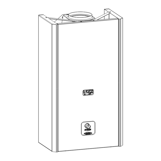
Page 4: Structural Drawing
DIMENSIONS Fig. 1. 1. Structural drawing Deflector Temperature knob Case Flue-gas backflow sensor Purging screw Limiter thermostat Thermistor Heat exchanger Return heating pipe Boiler shell Back sheet Thermocouple Pump Burner Gas inlet pipe Delivery water Pilot flame holder Delivery pipe Gas valve Gas connection Electric control box... -
Page 5: Hydraulic Scheme Of Ch Wall-Mounted Boilers
1.2 Hydraulic scheme of CH wall-mounted boilers 230 V, 50 Hz Electric control box 12 Magnetic valve Gas inlet 13 Gas valve Thermocouple 14 Display Burner Pump Heat exchanger 16 Expansion pipe Delivery temperature 17 Mains connection sensor NTC 18 Room temperature controller Limiter thermostat 19 Charging-discharging valve Delivery pipe... -
Page 6: Technical Data
1.3 Technical data Trademark: C24H Manufacturer: Novum-Fég Fűtéstechnikai és készülékgyártó Kft. Type: B 11BS Type of gas: II 2HS3B/P Allowed maximum operating pressure: 3 bars Allowed maximum heating water temperature: 90 ºC Type of gas: „H” natural gas „S” natural gas Propane gas Joint gas pressure: 25 mbar... -
Page 7: Airing Of Rooms
O132 G 1/2 G3/4 G 3/4 Fig. 4. 1. Insert plugs into the wall at the distances and heights shown in Figure 4. 2. Drive in the screws. 3. Hang the appliance on the screws through the openings of the back sheet. Water connections The delivery and return pipes must be equipped with closing fittings. -
Page 8: Flue Gas Piping
-Between 1750-3140 W/m³ specific load the room must be ventilated to another room by 2 pcs. of non-lockable vents. The cross section of these must be at least 1510 cm² and there must be a minimum of 1,8 m vertical distance between them. In this case the next parameters have to be realized: -total specific load must be under than 1250W/m³. -
Page 9: Filling And Putting Into Operation
2.5. Filling and putting into operation Filling must be carried out by soft water. Before starting filling every valve must be opened and the outlet valves must be closed. Air discharging valves are to be opened and ensure that the caps of automatic ones' are opened to 1-2 turns. -
Page 10: Connecting Of Room Thermostat
-DWT thermistor -display Jumper can be found: -between points 8 and 9 -and 10 and 11 2. 7 Connecting of room thermostat: For operation of the boiler the room thermostat must be connected. -Remove jumper between points 8 and 9. -Wire up to points 8 and 9 the heating operating contacts of room thermostat. -
Page 11: Installation
2.8. Installation When preparation is carried out installation may start. Its steps are: (3) Adjust room thermostat to a temperature lower than of ambience. (4) Apply voltage to the appliance: plug the cable of boiler into the wall socket. • The actual delivery water temperature appears in the display, showing range 3-91 ºC. -
Page 12: Frost Protection
Error signals and their correction: If heating stops because of an error a fault sign appears in the display. From the signal the conclusion can be drawn to the cause of error. Error of DWT sensor (ErC) Sign in display: Cause of failure can be: •... -
Page 13: First Installation
F1 1000 mA F Pump Mains connection ~230 V / 50Hz Mains out ~230 V / 50Hz Room thermostat LOCK I. Lock Magnetic valve P1 pot.meter 14 15 16 17 18 19 20 21 22 Display CH12-40 control panel Connection Diagram C 12H, C 18H, C 24H, C 40H Fig. -
Page 14: Installation And Shut Down
2.11. Installation and shut down Instructions for installation and shut down of boiler see in chapter 3. INSTRUCTIONS FOR USE AND MAINTENANCE FOR USERS. 2.12. Adjustment of burner pressure The next instructions are only for technicians authorized to service. Every appliance is put into circulation in a tested and adjusted state. The output of a heating appliance can be adjusted between values shown in Table 1. -
Page 15: Adjustment For Another Type Of Gas
2.13. Adjustment for another type of gas The boilers are adjusted for another type of gas in accordance with the consumer's order. Later modifications can only be done by a skilled person who installs parts made by NOVUM-FÉG expressly for this aim and carries out adjustment and change in a proper way. For modification the next procedure is to be done: ADJUSTED! Fig. -
Page 16: Instructions For Use And Maintenance For Users
- Check the cleanliness of boiler lamellas. If these are dirty then after draining water off the appliance demount the heat exchanger and flush it by water jet. After drying the heat exchanger is to be sprayed by heat resistant silver paint to prevent flue-gas corrosion. - In case of boilers older than 4-5 years inside the coil scale or other deposits may develop (this effect is signed by rumbling of the boiler). -
Page 17: Shut-Down
Pilot flame Button Display Fig. 8. Temperature controller knob By the effect of adjustment the display changes to the adjusted value. After 2 seconds the display changes back and continuously shows the actual temperature of delivery heating water. Continuous Display of display adjustment Raise the temperature of water only when the low value does not ensure the required temperature of... - Page 18 Annually have the appliance serviced, which must be documented in the warranty! Servicemen of the local gas company must supervise the appliance every five years! ATTENTION! The boiler has got a flue-gas backflow sensor. When it starts operation the boiler stops automatically. Restart can only be made by manual ignition of pilot flame.
Need help?
Do you have a question about the C 24 H and is the answer not in the manual?
Questions and answers